EP2783799A2 - Système de robot et procédé de transfert de pièces - Google Patents
Système de robot et procédé de transfert de pièces Download PDFInfo
- Publication number
- EP2783799A2 EP2783799A2 EP14157160.4A EP14157160A EP2783799A2 EP 2783799 A2 EP2783799 A2 EP 2783799A2 EP 14157160 A EP14157160 A EP 14157160A EP 2783799 A2 EP2783799 A2 EP 2783799A2
- Authority
- EP
- European Patent Office
- Prior art keywords
- robot
- holder
- workpiece
- robot arm
- arm
- Prior art date
- Legal status (The legal status is an assumption and is not a legal conclusion. Google has not performed a legal analysis and makes no representation as to the accuracy of the status listed.)
- Withdrawn
Links
Images






Classifications
-
- B—PERFORMING OPERATIONS; TRANSPORTING
- B25—HAND TOOLS; PORTABLE POWER-DRIVEN TOOLS; MANIPULATORS
- B25J—MANIPULATORS; CHAMBERS PROVIDED WITH MANIPULATION DEVICES
- B25J9/00—Program-controlled manipulators
- B25J9/16—Program controls
- B25J9/1612—Program controls characterised by the hand, wrist, grip control
-
- B—PERFORMING OPERATIONS; TRANSPORTING
- B25—HAND TOOLS; PORTABLE POWER-DRIVEN TOOLS; MANIPULATORS
- B25J—MANIPULATORS; CHAMBERS PROVIDED WITH MANIPULATION DEVICES
- B25J15/00—Gripping heads and other end effectors
- B25J15/06—Gripping heads and other end effectors with vacuum or magnetic holding means
- B25J15/0616—Gripping heads and other end effectors with vacuum or magnetic holding means with vacuum
-
- B—PERFORMING OPERATIONS; TRANSPORTING
- B25—HAND TOOLS; PORTABLE POWER-DRIVEN TOOLS; MANIPULATORS
- B25J—MANIPULATORS; CHAMBERS PROVIDED WITH MANIPULATION DEVICES
- B25J9/00—Program-controlled manipulators
- B25J9/16—Program controls
-
- B—PERFORMING OPERATIONS; TRANSPORTING
- B25—HAND TOOLS; PORTABLE POWER-DRIVEN TOOLS; MANIPULATORS
- B25J—MANIPULATORS; CHAMBERS PROVIDED WITH MANIPULATION DEVICES
- B25J9/00—Program-controlled manipulators
- B25J9/16—Program controls
- B25J9/1615—Program controls characterised by special kind of manipulator, e.g. planar, scara, gantry, cantilever, space, closed chain, passive/active joints and tendon driven manipulators
-
- G—PHYSICS
- G05—CONTROLLING; REGULATING
- G05B—CONTROL OR REGULATING SYSTEMS IN GENERAL; FUNCTIONAL ELEMENTS OF SUCH SYSTEMS; MONITORING OR TESTING ARRANGEMENTS FOR SUCH SYSTEMS OR ELEMENTS
- G05B2219/00—Program-control systems
- G05B2219/30—Nc systems
- G05B2219/40—Robotics, robotics mapping to robotics vision
- G05B2219/40006—Placing, palletize, un palletize, paper roll placing, box stacking
Definitions
- the present invention relates to a robot system and a method for transferring a workpiece.
- Japanese Unexamined Patent Application Publication No. 2001-317911 discloses a depalletizing apparatus that includes a robot arm.
- the robot arm includes a hand to hold a workpiece placed on a pallet.
- the depalletizing apparatus captures an image of the workpiece from above the pallet and detects the position of the workpiece based on the captured image.
- the robot arm is moved based on the detected position of the workpiece, and the hand holds the workpiece.
- the present disclosure has been made in view of the above-described circumstances, and it is one object of the present disclosure to provide a robot system and a method for transferring a workpiece that eliminate or minimize contact of the robot arm with the workpiece placement stand when the robot arm holds a workpiece.
- a robot system 100 includes a first robot arm 14 and a robot controller 6.
- the first robot arm 14 is configured to extend in a first direction and includes a holder 12 configured to hold a workpiece placed on a workpiece placement stand 201.
- the holder 12 includes a distal end portion and a base portion.
- the base portion is coupled to the first robot arm 14 such that a turning axis of a portion of the first robot arm 14 to which the base portion of the holder 12 is coupled is apart from a geometrical center of the holder 12.
- the robot controller 6 is configured to control the holder 12 to hold the workpiece placed on the workpiece placement stand 201 while controlling the first robot arm 14 to turn the holder 12 with the distal end portion of the holder 12 oriented in a direction crossing the first direction.
- the base portion of the holder is coupled to the first robot arm such that the turning axis of a portion of the first robot arm to which the base portion of the holder is coupled is apart from the geometrical center of the holder.
- the robot controller controls the holder to hold the workpiece placed on the workpiece placement stand while controlling the first robot arm to turn the holder such that the distal end portion of the holder is oriented in a direction crossing the first direction, in which the first robot arm extends. This ensures that when holding the workpiece, the first robot arm is able to come closer to the center of the workpiece placement stand by the amount of the turning of the distal end portion of the holder in a direction crossing the first direction. This eliminates or minimizes contact of the first robot arm with the workpiece placement stand (on the circumference (wall) of the workpiece placement stand) when the first robot arm holds the workpiece.
- a method for transferring a workpiece includes controlling a robot arm 14 to turn a holder 12 including a distal end portion and a base portion that is coupled to the robot arm 14 so as to orient the distal end portion of the holder 12 in a direction crossing a first direction in which the robot arm 14 is configured to extend, and so as to make a turning axis of a portion of the robot arm 14 to which the base portion of the holder 12 is coupled apart from a geometrical center of the holder 12.
- the holder 12 is controlled to turn to hold a workpiece placed on a workpiece placement stand 201.
- the method for transferring a workpiece includes controlling a robot arm to turn a holder including a distal end portion and a base portion that is coupled to the robot arm so as to orient the distal end portion of the holder in a direction crossing a first direction in which the robot arm is configured to extend, and so as to make a turning axis of a portion of the robot arm to which the base portion of the holder is coupled apart from a geometrical center of the holder.
- This ensures that when holding the workpiece, the first robot arm is able to come closer to the center of the workpiece placement stand by the amount of the turning of the distal end portion of the holder in a direction crossing the first direction.
- This makes the method for transferring a workpiece a method that eliminates or minimizes contact of the first robot arm with the workpiece placement stand (on the circumference (wall) of the workpiece placement stand) when the first robot arm holds the workpiece.
- FIGs. 1 to 15 a configuration of a robot system 100 according to an embodiment will be described by referring to FIGs. 1 to 15 .
- the robot system 100 includes a depalletizing robot 1 and a detection robot 2.
- the detection robot 2 detects a workpiece 200.
- Examples of the depalletizing robot 1 and the detection robot 2 include, but are not limited to, a perpendicularly articulated robot.
- a pallet 201 is disposed adjacent to (on an X1 direction side of) the depalletizing robot 1 and the detection robot 2.
- On the pallet 201 a plurality of workpieces 200 of different sizes and shapes are stacked. Examples of the workpiece 200 include, but are not limited to, a box-shaped workpiece.
- the pallet 201 has an approximately rectangular shape (that is, a box-shape having walls).
- the approximately rectangular shape of the pallet 201 surrounds the workpieces 200.
- a conveyor 202 is disposed adjacent to (on a Y2 direction side of) the depalletizing robot 1.
- the conveyor 202 receives (and transfers) the workpiece 200.
- the pallet 201 is an example of the "workpiece placement stand
- the depalletizing robot 1 is coupled to a robot controller 3.
- the detection robot 2 is coupled to a robot controller 4.
- the robot controller 3 and the robot controller 4 are coupled to a PLC (programmable logic controller) 5.
- the PLC 5 is coupled to a PC (Personal Computer) 6.
- the PC 6 controls an overall operation of the robot system 100.
- the PC 6 is also coupled to a laser light emitting device 7 and a camera 8.
- the laser light emitting device 7 and the camera 8 detect the arrangement state of the workpiece 200.
- the PC 6 is an example of the "robot controller”.
- the depalletizing robot 1 includes a robot main body 11 and a robot hand 12.
- the robot hand 12 is mounted on the distal end of the robot main body 11 in order to suck and hold the workpiece 200 placed on the pallet 201.
- the robot main body 11 includes a base 13 and a robot arm 14.
- the depalletizing robot 1 includes a cable 15 and other elements coupled to the robot arm 14.
- the robot hand 12 is an example of the "holder”.
- the robot arm 14 is an example of the "first robot arm”.
- the base 13 is secured to an installation surface such as a floor, a wall, and a ceiling.
- the robot arm 14 has five degrees of freedom.
- the robot arm 14 includes a plurality of arm structures.
- An arm structure 141 is coupled to the base 13 in a rotatable manner about a rotation axis A1, which is perpendicular to the installation surface.
- An arm structure 142 is coupled to the arm structure 141 in a rotatable manner about a rotation axis A2, which is perpendicular to the rotation axis A1.
- An arm structure 143 is coupled to the arm structure 142 in a rotatable manner about a rotation axis A3, which is parallel to the rotation axis A2.
- An arm structure 144 is coupled to the arm structure 143 in a rotatable manner about a rotation axis A4, which is parallel to the rotation axis A3.
- An arm structure 145 is coupled to the arm structure 144 in a rotatable manner about a rotation axis A5, which is perpendicular to the rotation axis A4.
- Each of the rotation axes A1 to A5 is equipped with a servo motor.
- Each servo motor includes an encoder to detect the rotation position of the servo motor.
- Each servo motor is coupled to the robot controller 3. Thus, each servo motor operates based on a command from the robot controller 3.
- the depalletizing robot 1 is asymmetric with respect to a center line C, which is aligned in an X direction, in which the robot arm 14 of the depalletizing robot 1 extends, such that the robot arm 14 protrudes to one side (a Y1 direction side) of a Y direction.
- the cable 15 also protrudes to the Y1 direction side.
- the phase "in plan view” means "when seen from a direction opposite the workpiece at the time of holding of the workpiece (in many cases, from upward in the direction of gravitational force)".
- a base portion (which is on an X2 direction side) of the robot hand 12 is coupled to the robot arm 14 (more specifically, to the arm structure 145) such that in plan view, a turning axis A5 of the portion (that is, the arm structure 145) of the robot arm 14 to which the base portion of the robot hand 12 is coupled is apart from the geometrical center (the point A, which is the geometrical center of gravity) of the robot hand 12.
- the robot hand 12 has an approximately square shape in plan view, and is coupled to the robot arm 14 at a position adjacent to a corner 12a of the base portion of the approximately square shape of the robot hand 12.
- the base portion of the robot hand 12 coupled to the robot arm 14 is at a position offset from the geometrical center of the robot hand 12 (that is, from the point A) by a predetermined distance d in the Y direction (more specifically, to a Y2 direction), which is orthogonal to the X direction, in which the robot arm 14 extends.
- the robot hand 12 is coupled to the robot arm 14 at a position in the base portion of the robot hand 12 offset by the predetermined distance d in the Y2 direction side, which is opposite to the direction (the Y1 direction) in which the robot arm 14 (as well as the cable 15) protrudes.
- the robot arm 14 and the robot hand 12 are coupled to each other via a coupling device (bracket) 16.
- the robot hand 12 includes a plurality of suction devices 121 and a robot hand main body 122.
- the plurality of suction devices 121 hold the workpiece 200 placed on the pallet 201 by gaseous suction force (or pneumatic suction force).
- the plurality of suction devices 121 are mounted on the robot hand main body 122.
- the PC 6 controls the robot hand 12 to hold the workpiece 200 such that some of the suction devices 121 positioned at a portion where the workpiece 200 and the robot hand 12 overlap are switched to operation mode, while the other suction devices 121 are left in nonoperation mode. For example, as shown in FIGs.
- the PC 6 controls the suction devices 121 to hold the workpiece 200 placed on the pallet 201 while controlling the robot arm 14 to turn the suction devices 121 such that the distal end portions of the suction devices 121 are oriented in a direction (an E1 direction or an E2 direction) crossing the X direction, in which the robot arm 14 extends.
- the PC 6 also controls the robot hand 12 to hold the workpiece 200 while controlling the robot arm 14 to turn the suction devices 121 such that in plan view, the distal end portion of the robot hand 12 is oriented in the direction crossing the X direction (the E1 direction and the E2 direction) from a basic state in which the distal end portion and the base portion of the robot hand 12 are aligned in the X direction (see FIG. 4 ).
- the PC 6 controls the robot hand 12 to hold the workpiece 200 while controlling the robot arm 14 to turn the robot hand 12 to the Y2 direction side from the basic state (see FIG. 4 ).
- the PC 6 controls the robot hand 12 to hold the workpiece 200 while controlling the robot arm 14 to turn the robot hand 12 to the Y1 direction side from the basic state.
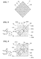
- the PC 6 controls the suction devices 121 to hold the workpiece 200 while controlling the robot arm 14 to turn the robot hand 12 by approximately 45 degrees such that two sides 12b and 12c (that is, outer edges) of the approximately square shape of the robot hand 12, which are orthogonal to each other at the distal end portion of the robot hand 12, are respectively parallel to two sides 201a and 201b of the pallet 201.
- the robot hand 12 holds the workpiece 200 while being held moved (or turned) by the robot arm 14 in the following manner.
- the two sides 12b and 12c that is, the outer edges
- the robot hand 12 which are orthogonal to each other at the distal end portion of the robot hand 12, respectively overlap the sides 200a and 200b of the workpiece 200, and a corner 12d of the distal end portion of the robot hand 12 overlaps a corner 200c of the workpiece 200.
- the robot hand 12 holds the workpiece 200 such that the two sides 12b and 12c (that is, the outer edges) of the robot hand 12 respectively overlap two of the four sides of the workpiece 200, and such that the corner 12d of the distal end portion of the robot hand 12 overlaps one of the four corners of the workpiece 200.
- the robot hand 12 holds the workpiece 200 while being moved (or turned) by the robot arm 14 in the following manner.
- the two sides 12b and 12c that is, outer edges
- the robot hand 12 which are orthogonal to each other at the distal end portion of the robot hand 12, respectively overlap the two corners 200c and 200d of the workpiece 200.
- the robot 2 includes a robot main body 21 and a robot hand 22.
- the robot hand 22 is mounted on the distal end of the robot main body 21.
- the robot main body 21 includes a base 23 and a robot arm 24.
- the base 23 is secured to an installation surface such as a floor, a wall, and a ceiling.
- the robot arm 24 has six degrees of freedom.
- the robot arm 24 includes a plurality of arm structures.
- An arm structure 241 is coupled to the base 23 in a rotatable manner about a rotation axis B1, which is perpendicular to the installation surface.
- An arm structure 242 is coupled to the arm structure 241 in a rotatable manner about a rotation axis B2, which is perpendicular to the rotation axis B 1.
- An arm structure 243 is coupled to the arm structure 242 in a rotatable manner about a rotation axis B3, which is parallel to the rotation axis B2.
- An arm structure 244 is coupled to the arm structure 243 in a rotatable manner about a rotation axis B4, which is perpendicular to the rotation axis B3.
- An arm structure 245 is coupled to the arm structure 244 in a rotatable manner about a rotation axis B5, which is perpendicular to the rotation axis B4.
- An arm structure 246 is coupled to the arm structure 245 in a rotatable manner about a rotation axis B6, which is perpendicular to the rotation axis B5.
- Each of the rotation axes B1 to B6 is equipped with a servo motor (joint).
- Each servo motor includes an encoder to detect the rotation position of the servo motor.
- Each servo motor is coupled to the robot controller 4.
- each servo motor operates based on a command from the robot controller 4.
- the robot arm 24 is an example of the "second robot arm”.
- the robot hand 22 includes the laser light emitting device 7 and the camera 8 (that is, a stereoscopic camera).
- the laser light emitting device 7 emits laser light to the workpiece 200.
- the camera 8 detects the laser light reflected from the workpiece 200.
- the laser light emitting device 7 and the camera 8 are an example of the "detector".
- the laser light emitting device 7 emits, for example, cross-shaped laser light (that is, laser light crossing each other) to the workpiece 200.
- the camera 8 detects (that is, captures an image of) the laser light reflected from the workpiece 200.
- the PC 6 calculates (or measures) an arrangement state of the workpiece 200 (such as the height of the workpiece 200 (more specifically, the height position of the upper surface of the workpiece 200), and the rotational angle, position, shape, and size of the workpiece 200). Then, in this embodiment, the PC 6 controls the robot arm 14 to move based on the arrangement state of the workpiece 200 detected by the laser light emitting device 7 and the camera 8, and controls the robot hand 12 to hold the workpiece 200 placed on the pallet 201.
- an arrangement state of the workpiece 200 such as the height of the workpiece 200 (more specifically, the height position of the upper surface of the workpiece 200), and the rotational angle, position, shape, and size of the workpiece 200.
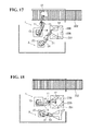
- step S1 based on the latest detection operation by the laser light emitting device 7 and the camera 8 detecting the arrangement state of the workpiece 200 disposed on the uppermost level of the pallet 201, the robot hand 12 of the robot arm 14 holds the workpiece 200, and the robot arm 14 moves to place the workpiece 200 onto the conveyor 202, as shown in FIG. 17 .
- the robot arm 24 moves to arrange the robot hand 22 (the laser light emitting device 7 and the camera 8), which are mounted on the robot arm 24, over the pallet 201.
- step S2 the laser light emitting device 7 emits laser light to the workpiece 200, and the camera 8 captures an image of the laser light reflected from the workpiece 200 so as to detect an arrangement state (such as height, shape, and size) of a workpiece 200 next to be held on the pallet 201. Then, the next-to-be-held workpiece 200 (which is, for example, disposed on the uppermost level) is selected among a plurality of detected workpieces 200.
- an arrangement state such as height, shape, and size
- step S3 the robot arm 14 moves to a position over the pallet 201. Then, simultaneously with the movement operation of the robot arm 14, the robot arm 24 is withheld in a direction apart from the pallet 201 from the position adjacent to the pallet 201 in order to avoid collision with the robot arm 14.
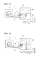
- step S4 when the workpiece 200 to be held is disposed on, for example, the Y2 direction side (or on the Y1 direction side), which is orthogonal to the X direction, then as shown in FIGs. 10 and 11 (or FIGs. 12 and 13 ), the robot arm 14 turns the robot hand 12 by approximately 45 degrees to the Y2 direction side (or to the Y1 direction side) from the basic state (see FIG. 4 ). Then, the robot hand 12 moves to a position over the next-to-be-held workpiece 200.
- step S5 the robot hand 12 holds the workpiece 200 such that in plan view, some of the suction devices 121 positioned at the portion where the workpiece 200 and the robot hand 12 overlap are switched to operation mode, while the other suction devices 121 are left in nonoperation mode.
- the processing returns to step S1, where the workpiece 200 is placed onto the conveyor 202. After the workpiece 200 is placed on the conveyor 202, all the suction devices 121 are switched to nonoperation mode.
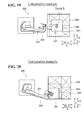
- a robot hand 301 is coupled to a robot arm 302 at the geometrical center (that is, at a point B) of the robot hand 301.
- a cable 303 comes into contact with the pallet 201.
- the robot hand 12 is coupled to the robot arm 14 at the base portion of the robot hand 12 such that the turning axis A5 of the robot arm 14 is apart from the geometrical center of the robot hand 12.
- the robot hand 12 holds the workpiece 200 while being turned by approximately 45 degrees to the Y1 direction side (which also applies to the case where the workpiece 200 is disposed on the Y2 direction side).
- the robot arm 14 is closer to the center of the pallet 201 than the robot arm 302 shown in FIG. 20 is to the center of the pallet 201. This eliminates or minimizes contact between the depalletizing robot 1 (as well as the cable 15) and the pallet 201. As shown in FIGs. 10 to 13 , no or minimal contact occurs between the depalletizing robot 1 (as well as the cable 15) and the pallet 201 no matter where on the pallet 201 the workpiece 200 to be held is disposed.
- the base portion of the robot hand 12 is coupled to the robot arm 14 such that the turning axis A5 of the portion of the robot arm 14 to which the base portion of the robot hand 12 is coupled is apart from the geometrical center of the robot hand 12.
- the PC 6 controls the robot hand 12 to hold the workpiece 200 placed on the pallet 201 while controlling the robot arm 14 to turn the robot hand 12 such that the distal end portion of the robot hand 12 is oriented in a direction crossing the X direction, in which the robot arm 14 extends. This ensures that when holding the workpiece 200, the robot arm 14 is able to come closer to the center of the pallet 201 by the amount of the turning of the distal end portion of the robot hand 12 in the direction crossing the X direction. This eliminates or minimizes contact of the robot arm 14 with the pallet 201 (on the circumference (wall) of the pallet 201) when the robot hand 12 holds the workpiece 200.
- the PC 6 controls the robot hand 12 to hold the workpiece 200 while controlling the robot arm 14 to turn the robot hand 12 such that in plan view, an outer edge of the distal end portion of the robot hand 12 is approximately parallel to an outer edge of the pallet 201.
- the suction devices 121 disposed on the distal end portion of the robot hand 12 are in use in most cases. This facilitates selection of the suction devices 121 in holding the workpiece 200, as opposed to the selective use of the suction devices 121 depending on where the workpiece 200 is arranged; only those suction devices 121 at the center of the robot hand 12 are used in some cases, while in other cases only those suction devices 121 at the base portion of the robot hand 12 are used.
- the PC 6 controls the robot hand 12 to hold the workpiece 200 while controlling the robot arm 14 to turn the robot hand 12 by approximately 45 degrees such that the two sides 12b and 12c of the robot hand 12, which are orthogonal to each other at the distal end portion of the approximately square shape of the robot hand 12, are approximately parallel to the two sides 201a and 201b of the pallet 201.
- the outer edges of the robot hand 12 are positioned along the corresponding outer edges of the workpiece 200. This ensures reliable holding of the workpiece 200 with the workpiece 200 and the robot hand 12 overlapping each other.
- the PC 6 controls the robot hand 12 to hold the workpiece 200 while controlling the robot arm 14 to turn the robot hand 12 such that in plan view, the distal end portion of the robot hand 12 is oriented in a direction crossing the X direction from the basic state in which the distal end portion and the base portion of the robot hand 12 are aligned in the X direction.
- the PC 6 controls the robot hand 12 to hold the workpiece 200 while controlling the robot arm 14 to turn the robot hand 12 to the one side of the Y direction from the basic state.
- the PC 6 controls the robot hand 12 to hold the workpiece 200 while controlling the robot arm 14 to turn the robot hand 12 to the other side of the Y direction from the basic state.
- turning the robot hand 12 by approximate 45 degree ensures holding of the workpiece 200 disposed on the one side or the other side of the robot hand 12. This eliminates or minimizes lengthening of the tact time for the operation of holding the workpiece 200 caused by turning of the robot hand 12 by a larger degree (larger than 45 degrees).
- the base portion of the robot hand 12 coupled to the robot arm 14 is at a position offset in the Y direction, which is orthogonal to the X direction, from the geometrical center of the robot hand 12. This ensures that the robot arm 14 is disposed closer to the center of the pallet 201 by the amount of the offset of the robot hand 12 in the Y direction. This effectively eliminates or minimizes contact between the robot arm 14 and the pallet 201.
- the depalletizing robot 1 is asymmetric with respect to the center line C of the depalletizing robot 1, which is aligned in the X direction such that the robot arm 14 protrudes to one side of the Y direction (that is, to the Y1 direction side).
- the base portion of the robot hand 12 coupled to the robot arm 14 is at a position offset to the other side (that is, to the Y2 direction side) of the Y direction opposite to the Y1 direction side, to which the robot arm 14 protrudes.
- the robot arm 24 includes the laser light emitting device 7 and the camera 8 to detect an arrangement state of the workpiece 200 placed on the pallet 201.
- the PC 6 controls the robot arm 14 to move based on the arrangement state of the workpiece 200 detected by the laser light emitting device 7 and the camera 8, and controls the robot hand 12 to hold the workpiece 200 placed on the pallet 201. This facilitates holding of the workpiece 200 placed on the pallet 201 based on the arrangement state of the workpiece 200 detected by the laser light emitting device 7 and the camera 8.
- the above-described embodiment has been illustrated as using two robots, namely, the depalletizing robot having five degrees of freedom and the detection robot having six degrees of freedom to detect an arrangement state of the workpiece disposed on the pallet and to hold and transfer the workpiece. It is also possible to use a single two-arm robot to detect an arrangement state of the workpiece disposed on the pallet and to hold and transfer the workpiece.
- the number of control axes for each of the depalletizing robot and the detection robot is selectable conveniently. For example, it is possible to use a robot arm having four degrees of freedom or a robot arm having more than four degrees of freedom for each of the depalletizing robot and the detection robot.
- the robot hand has been illustrated as holding the workpiece at the distal end portion of the robot hand.
- the robot hand may also hold the workpiece at the center of the robot hand, for example.
- the robot hand has been illustrated as having an approximately square shape in plan view.
- a robot hand 31 according to a first modification shown in FIG. 21 .
- the robot hand 31 has an approximately triangular shape having two sides orthogonal to each other at the distal end portion of the robot hand 31.
- a robot hand 32 according to a second modification shown in FIG. 22 .
- the robot hand 32 has an approximately hexagonal shape having two sides orthogonal to each other at the distal end portion of the robot hand 32.
- the robot hand may also have a shape other than a polygonal shape such as an approximately square shape (examples including, but not limited to, an elliptical shape).
- the base portion of the robot hand is coupled to the robot arm such that the turning axis A5 of the portion of the robot arm to which the base portion of the robot hand is coupled is apart from the geometrical center (that is, the geometrical center of gravity) of the robot hand.
- the robot hands 31 and 32 are examples of the "holder".
- the robot hand has been illustrated as holding the workpiece while being turned by approximately 45 degrees by the robot hand.
- the robot hand may also hold the workpiece while being turned by other than approximately 45 degrees.
- the robot hand has been illustrated as holding the workpiece while being turned by the robot arm from the basic state in which the distal end portion and the base portion of the robot hand are aligned in the X direction (see FIG. 4 ).
- the distal end portion of the robot hand is turned in advance, and from this state, the robot hand is further turned to a position corresponding to the position of the workpiece so as to hold the workpiece.
- the base portion of the robot hand coupled to the robot arm has been illustrated as being, in plan view, at a position offset in the Y direction, which is orthogonal to the X direction, from the geometrical center of the robot hand.
- Another possible example is to couple the robot hand to the robot arm without making the robot hand offset in the Y direction.
- the base portion of the robot hand is coupled to the robot arm such that the turning axis of the portion of the robot arm to which the base portion of the robot hand is coupled is offset from the geometrical center of the robot hand.
- the base portion of the robot hand coupled to the robot arm has been illustrated as being at a position offset in a direction opposite to the direction in which the robot arm protrudes.
- Another possible example is to make the robot hand offset in the same direction in which the robot arm protrudes and to couple the robot hand to the robot arm.
- a depalletizing operation has been illustrated, in which the workpieces stacked on the pallet are depalletized by the robot system.
- the robot system may also perform an operation other than the depalletizing operation, examples including, but not limited to, a palletizing operation.
- the PC has been illustrated as controlling the operation of the robot (the robot system). It is also possible to use a PLC or a robot controller to control the operation of the robot.
- pneumatic suction force is used to hold the workpiece. It is also possible to use electromagnetic suction force (that is, magnetic force using a magnet) to hold the workpiece.
Landscapes
- Engineering & Computer Science (AREA)
- Robotics (AREA)
- Mechanical Engineering (AREA)
- Health & Medical Sciences (AREA)
- General Health & Medical Sciences (AREA)
- Orthopedic Medicine & Surgery (AREA)
- Manipulator (AREA)
Applications Claiming Priority (1)
| Application Number | Priority Date | Filing Date | Title |
|---|---|---|---|
| JP2013052163A JP5768827B2 (ja) | 2013-03-14 | 2013-03-14 | ロボットシステムおよびワークの搬送方法 |
Publications (2)
| Publication Number | Publication Date |
|---|---|
| EP2783799A2 true EP2783799A2 (fr) | 2014-10-01 |
| EP2783799A3 EP2783799A3 (fr) | 2015-03-04 |
Family
ID=50238145
Family Applications (1)
| Application Number | Title | Priority Date | Filing Date |
|---|---|---|---|
| EP14157160.4A Withdrawn EP2783799A3 (fr) | 2013-03-14 | 2014-02-28 | Système de robot et procédé de transfert de pièces |
Country Status (4)
| Country | Link |
|---|---|
| US (1) | US9352463B2 (fr) |
| EP (1) | EP2783799A3 (fr) |
| JP (1) | JP5768827B2 (fr) |
| CN (1) | CN104044139B (fr) |
Cited By (5)
| Publication number | Priority date | Publication date | Assignee | Title |
|---|---|---|---|---|
| CN107479581A (zh) * | 2017-09-21 | 2017-12-15 | 北京京东尚科信息技术有限公司 | 货箱码放控制装置、系统、方法和存储介质 |
| WO2019169417A1 (fr) * | 2018-03-09 | 2019-09-12 | Tgw Logistics Group Gmbh | Système robotisé permettant de saisir une marchandise dans un système de stockage et de préparation de commandes et procédé de fonctionnement s'y rapportant |
| US12037194B2 (en) | 2018-03-09 | 2024-07-16 | Tgw Logistics Group Gmbh | Robot system with motion sequences adapted to product types, and operating method therefor |
| US12098037B2 (en) | 2018-03-09 | 2024-09-24 | Tgw Logistics Group Gmbh | Picking station and method for automatic picking of goods |
| US12427656B2 (en) | 2018-03-09 | 2025-09-30 | Tgw Logistics Gmbh | Robot system for testing a loading space of a loading aid in a storage and order-picking system and operating method therefor |
Families Citing this family (15)
| Publication number | Priority date | Publication date | Assignee | Title |
|---|---|---|---|---|
| JP6380828B2 (ja) * | 2014-03-07 | 2018-08-29 | セイコーエプソン株式会社 | ロボット、ロボットシステム、制御装置、及び制御方法 |
| US9693166B2 (en) | 2014-06-24 | 2017-06-27 | The Boeing Company | Automated production of acoustic structures |
| EP3258762B1 (fr) * | 2015-02-12 | 2019-12-04 | FUJI Corporation | Dispositif d'introduction de composants |
| JP2017196705A (ja) * | 2016-04-28 | 2017-11-02 | セイコーエプソン株式会社 | ロボット、及びロボットシステム |
| US11072074B2 (en) * | 2017-12-13 | 2021-07-27 | Cognex Corporation | Calibration and operation of vision-based manipulation systems |
| SE1751548A1 (en) * | 2017-12-14 | 2019-06-15 | Tomologic Ab | A method and a system for handling beam-cut parts |
| CN107901054A (zh) * | 2017-12-27 | 2018-04-13 | 江苏聚力智能机械股份有限公司 | 一种驱动总成安装半自动化流水线 |
| WO2019197879A1 (fr) * | 2018-04-11 | 2019-10-17 | Fives Oto S.P.A. | Unité de transfert de tube |
| JP7117193B2 (ja) * | 2018-08-23 | 2022-08-12 | 川崎重工業株式会社 | ロボット及びそれを備えるロボットシステム |
| JP7371336B2 (ja) * | 2019-03-15 | 2023-10-31 | 富士電機株式会社 | 搬送装置 |
| DE102019112867A1 (de) * | 2019-05-16 | 2020-11-19 | Homag Automation Gmbh | Robotergreifer, Industrieroboter, Handhabungssystem und Verfahren zur Entnahme plattenförmiger Werkstücke von einem Stapel |
| JP7345372B2 (ja) * | 2019-11-29 | 2023-09-15 | 川崎重工業株式会社 | 保持装置、制御方法、制御装置及びロボットシステム |
| DK181570B1 (en) * | 2022-07-06 | 2024-05-28 | Onrobot As | Method and system for generating a trajectory for a robotic arm and a tool attached to the robotic arm |
| JP2024143745A (ja) * | 2023-03-30 | 2024-10-11 | 川崎重工業株式会社 | ロボット |
| EP4592040A1 (fr) * | 2024-01-29 | 2025-07-30 | Siemens Aktiengesellschaft | Système et procédé d'estimation de pose de prélèvement pour prélèvement robotique avec des effecteurs d'extrémité de taille arbitraire |
Family Cites Families (26)
| Publication number | Priority date | Publication date | Assignee | Title |
|---|---|---|---|---|
| US5177563A (en) * | 1989-02-01 | 1993-01-05 | Texas A&M University System | Method and apparatus for locating physical objects |
| US5606153A (en) * | 1994-04-07 | 1997-02-25 | R. J. Reynolds Tobacco Company | Robotic filter weighing system |
| JPH11163093A (ja) * | 1997-11-28 | 1999-06-18 | Nissin Electric Co Ltd | 基板搬送ロボット |
| JP2000141268A (ja) * | 1998-11-11 | 2000-05-23 | Daishin:Kk | マニピュレータ用ハンド装置 |
| JP3482938B2 (ja) | 2000-05-02 | 2004-01-06 | 株式会社ダイフク | 物品位置認識装置 |
| AU2003239171A1 (en) * | 2002-01-31 | 2003-09-02 | Braintech Canada, Inc. | Method and apparatus for single camera 3d vision guided robotics |
| JP3702257B2 (ja) * | 2002-08-23 | 2005-10-05 | ファナック株式会社 | ロボットハンドリング装置 |
| JP3805310B2 (ja) * | 2003-01-30 | 2006-08-02 | ファナック株式会社 | ワーク取出し装置 |
| US7783383B2 (en) * | 2004-12-22 | 2010-08-24 | Intelligent Hospital Systems Ltd. | Automated pharmacy admixture system (APAS) |
| US20060182607A1 (en) * | 2005-01-18 | 2006-08-17 | Clark Jason A | Method and apparatus for depalletizing bagged products |
| US8241271B2 (en) * | 2005-06-30 | 2012-08-14 | Intuitive Surgical Operations, Inc. | Robotic surgical instruments with a fluid flow control system for irrigation, aspiration, and blowing |
| JP4087874B2 (ja) * | 2006-02-01 | 2008-05-21 | ファナック株式会社 | ワーク取り出し装置 |
| JP2007283436A (ja) * | 2006-04-17 | 2007-11-01 | Nachi Fujikoshi Corp | ロボット、ロボットシステム及びハンド装置の姿勢制御方法 |
| KR100914386B1 (ko) * | 2006-07-11 | 2009-08-28 | 가부시키가이샤 야스카와덴키 | 다관절 로봇 |
| DE102007026956A1 (de) * | 2007-06-12 | 2008-12-18 | Kuka Innotec Gmbh | Verfahren und System zum Roboter geführten Depalettieren von Reifen |
| DE102007062534B4 (de) * | 2007-12-20 | 2018-01-11 | Kuka Roboter Gmbh | Vorrichtung zur Handhabung von Gegenständen, insbesondere von Gepäckstücken, Gepäckhandhabungssystem und Verfahren zum Aufnehmen und Umladen von Gegenständen bzw. Gepäckstücken |
| JP5196158B2 (ja) * | 2008-10-07 | 2013-05-15 | 日本電気硝子株式会社 | ガラス基板梱包装置およびその梱包方法 |
| US8941726B2 (en) * | 2009-12-10 | 2015-01-27 | Mitsubishi Electric Research Laboratories, Inc. | Method and system for segmenting moving objects from images using foreground extraction |
| JP5423441B2 (ja) * | 2010-02-03 | 2014-02-19 | 株式会社安川電機 | 作業システム、ロボット装置、機械製品の製造方法 |
| JP5229253B2 (ja) * | 2010-03-11 | 2013-07-03 | 株式会社安川電機 | ロボットシステム及びロボット装置並びにワーク取り出し方法 |
| JP2012056017A (ja) * | 2010-09-09 | 2012-03-22 | Honda Motor Co Ltd | ワーク搬送装置およびワーク搬送方法 |
| JP2013078825A (ja) * | 2011-10-04 | 2013-05-02 | Yaskawa Electric Corp | ロボット装置、ロボットシステムおよび被加工物の製造方法 |
| JP5447483B2 (ja) * | 2011-10-04 | 2014-03-19 | 株式会社安川電機 | ロボットシステムおよび被加工物の製造方法 |
| JP5266377B2 (ja) * | 2011-12-19 | 2013-08-21 | ファナック株式会社 | 物品の姿勢を修正する機能を備えた取出し装置 |
| US8892244B1 (en) * | 2012-01-09 | 2014-11-18 | Armorworks Enterprises LLC | Automated tile placement machine |
| DE102012018438B4 (de) * | 2012-09-19 | 2018-12-13 | Eisenmann Alpha-Tec Gmbh | Handhabungseinrichtung mit einem Manipulator für Materialstücke |
-
2013
- 2013-03-14 JP JP2013052163A patent/JP5768827B2/ja active Active
- 2013-12-26 CN CN201310739274.8A patent/CN104044139B/zh active Active
-
2014
- 2014-02-28 EP EP14157160.4A patent/EP2783799A3/fr not_active Withdrawn
- 2014-03-14 US US14/210,444 patent/US9352463B2/en not_active Expired - Fee Related
Cited By (9)
| Publication number | Priority date | Publication date | Assignee | Title |
|---|---|---|---|---|
| CN107479581A (zh) * | 2017-09-21 | 2017-12-15 | 北京京东尚科信息技术有限公司 | 货箱码放控制装置、系统、方法和存储介质 |
| CN107479581B (zh) * | 2017-09-21 | 2021-01-26 | 北京京东尚科信息技术有限公司 | 货箱码放控制装置、系统、方法和存储介质 |
| WO2019169417A1 (fr) * | 2018-03-09 | 2019-09-12 | Tgw Logistics Group Gmbh | Système robotisé permettant de saisir une marchandise dans un système de stockage et de préparation de commandes et procédé de fonctionnement s'y rapportant |
| EP3762187B1 (fr) | 2018-03-09 | 2022-06-22 | TGW Logistics Group GmbH | Système robotisé permettant de saisir une marchandise dans un système de stockage et de préparation de commandes et procédé de fonctionnement s'y rapportant |
| US12037194B2 (en) | 2018-03-09 | 2024-07-16 | Tgw Logistics Group Gmbh | Robot system with motion sequences adapted to product types, and operating method therefor |
| US12098037B2 (en) | 2018-03-09 | 2024-09-24 | Tgw Logistics Group Gmbh | Picking station and method for automatic picking of goods |
| US12139340B2 (en) | 2018-03-09 | 2024-11-12 | Tgw Logistics Group Gmbh | Robot system for gripping an item in a storage and picking system, and operating method for same |
| US12312172B2 (en) | 2018-03-09 | 2025-05-27 | Tgw Logistics Gmbh | Robot system with motion sequences adapted to product types, and operating method therefor |
| US12427656B2 (en) | 2018-03-09 | 2025-09-30 | Tgw Logistics Gmbh | Robot system for testing a loading space of a loading aid in a storage and order-picking system and operating method therefor |
Also Published As
| Publication number | Publication date |
|---|---|
| US9352463B2 (en) | 2016-05-31 |
| JP5768827B2 (ja) | 2015-08-26 |
| US20140277711A1 (en) | 2014-09-18 |
| CN104044139B (zh) | 2017-01-11 |
| CN104044139A (zh) | 2014-09-17 |
| JP2014176925A (ja) | 2014-09-25 |
| EP2783799A3 (fr) | 2015-03-04 |
Similar Documents
| Publication | Publication Date | Title |
|---|---|---|
| US9352463B2 (en) | Robot system and method for transferring workpiece | |
| EP2783801A2 (fr) | Système de robot et procédé de transfert de pièces | |
| EP2711144A1 (fr) | Système de robot et procédé de transfert de pièce à usiner | |
| US11958187B2 (en) | Robot hand, robot and robot system | |
| CN108495738B (zh) | 用于提供动态机器人控制系统的系统和方法 | |
| EP3680073B1 (fr) | Dispositif de transfert | |
| JP7117193B2 (ja) | ロボット及びそれを備えるロボットシステム | |
| JP6942576B2 (ja) | 搬送装置 | |
| CN117355392A (zh) | 集成移动机械手机器人 | |
| US20130085604A1 (en) | Robot apparatus, robot system, and method for producing a to-be-processed material | |
| JP7094506B2 (ja) | ルーティング安定化機構を備えたロボットシステム | |
| KR101952767B1 (ko) | 로봇 | |
| US11702297B2 (en) | Transfer method to drag grip target object | |
| US20140277734A1 (en) | Robot system and a method for producing a to-be-processed material | |
| JP5535884B2 (ja) | ワーク取り出し方法 | |
| US20250162159A1 (en) | Aligning a robotic arm to an object | |
| CN105417066B (zh) | 基板位置偏移检测及校正装置和基板搬运系统 | |
| EP2784612A2 (fr) | Système de robot et procédé de travail de robot | |
| CN103846906A (zh) | 机器人 | |
| JP2014061561A (ja) | ロボットシステムおよび物品製造方法 | |
| JP7134073B2 (ja) | 物品積載設備 | |
| US10675754B2 (en) | Robot system | |
| CN118574704A (zh) | 用于机器人碰撞避免的系统和方法 | |
| JP2023009036A (ja) | ロボットハンド及び搬送ロボットシステム | |
| JP2017056528A (ja) | 移送システムおよび移送方法 |
Legal Events
| Date | Code | Title | Description |
|---|---|---|---|
| 17P | Request for examination filed |
Effective date: 20140228 |
|
| AK | Designated contracting states |
Kind code of ref document: A2 Designated state(s): AL AT BE BG CH CY CZ DE DK EE ES FI FR GB GR HR HU IE IS IT LI LT LU LV MC MK MT NL NO PL PT RO RS SE SI SK SM TR |
|
| AX | Request for extension of the european patent |
Extension state: BA ME |
|
| PUAI | Public reference made under article 153(3) epc to a published international application that has entered the european phase |
Free format text: ORIGINAL CODE: 0009012 |
|
| PUAL | Search report despatched |
Free format text: ORIGINAL CODE: 0009013 |
|
| AK | Designated contracting states |
Kind code of ref document: A3 Designated state(s): AL AT BE BG CH CY CZ DE DK EE ES FI FR GB GR HR HU IE IS IT LI LT LU LV MC MK MT NL NO PL PT RO RS SE SI SK SM TR |
|
| AX | Request for extension of the european patent |
Extension state: BA ME |
|
| RIC1 | Information provided on ipc code assigned before grant |
Ipc: B25J 9/16 20060101AFI20150126BHEP |
|
| R17P | Request for examination filed (corrected) |
Effective date: 20150820 |
|
| RBV | Designated contracting states (corrected) |
Designated state(s): AL AT BE BG CH CY CZ DE DK EE ES FI FR GB GR HR HU IE IS IT LI LT LU LV MC MK MT NL NO PL PT RO RS SE SI SK SM TR |
|
| STAA | Information on the status of an ep patent application or granted ep patent |
Free format text: STATUS: THE APPLICATION HAS BEEN WITHDRAWN |
|
| 18W | Application withdrawn |
Effective date: 20160725 |