EP3680073B1 - Dispositif de transfert - Google Patents
Dispositif de transfert Download PDFInfo
- Publication number
- EP3680073B1 EP3680073B1 EP18853800.3A EP18853800A EP3680073B1 EP 3680073 B1 EP3680073 B1 EP 3680073B1 EP 18853800 A EP18853800 A EP 18853800A EP 3680073 B1 EP3680073 B1 EP 3680073B1
- Authority
- EP
- European Patent Office
- Prior art keywords
- grip
- package
- hold
- arm
- pad
- Prior art date
- Legal status (The legal status is an assumption and is not a legal conclusion. Google has not performed a legal analysis and makes no representation as to the accuracy of the status listed.)
- Active
Links
Images

Classifications
-
- B—PERFORMING OPERATIONS; TRANSPORTING
- B65—CONVEYING; PACKING; STORING; HANDLING THIN OR FILAMENTARY MATERIAL
- B65G—TRANSPORT OR STORAGE DEVICES, e.g. CONVEYORS FOR LOADING OR TIPPING, SHOP CONVEYOR SYSTEMS OR PNEUMATIC TUBE CONVEYORS
- B65G47/00—Article or material-handling devices associated with conveyors; Methods employing such devices
- B65G47/74—Feeding, transfer, or discharging devices of particular kinds or types
- B65G47/90—Devices for picking-up and depositing articles or materials
- B65G47/91—Devices for picking-up and depositing articles or materials incorporating pneumatic, e.g. suction, grippers
- B65G47/914—Devices for picking-up and depositing articles or materials incorporating pneumatic, e.g. suction, grippers provided with drive systems incorporating rotary and rectilinear movements
-
- B—PERFORMING OPERATIONS; TRANSPORTING
- B65—CONVEYING; PACKING; STORING; HANDLING THIN OR FILAMENTARY MATERIAL
- B65G—TRANSPORT OR STORAGE DEVICES, e.g. CONVEYORS FOR LOADING OR TIPPING, SHOP CONVEYOR SYSTEMS OR PNEUMATIC TUBE CONVEYORS
- B65G47/00—Article or material-handling devices associated with conveyors; Methods employing such devices
- B65G47/74—Feeding, transfer, or discharging devices of particular kinds or types
- B65G47/90—Devices for picking-up and depositing articles or materials
- B65G47/91—Devices for picking-up and depositing articles or materials incorporating pneumatic, e.g. suction, grippers
-
- B—PERFORMING OPERATIONS; TRANSPORTING
- B25—HAND TOOLS; PORTABLE POWER-DRIVEN TOOLS; MANIPULATORS
- B25J—MANIPULATORS; CHAMBERS PROVIDED WITH MANIPULATION DEVICES
- B25J15/00—Gripping heads and other end effectors
- B25J15/0052—Gripping heads and other end effectors multiple gripper units or multiple end effectors
-
- B—PERFORMING OPERATIONS; TRANSPORTING
- B25—HAND TOOLS; PORTABLE POWER-DRIVEN TOOLS; MANIPULATORS
- B25J—MANIPULATORS; CHAMBERS PROVIDED WITH MANIPULATION DEVICES
- B25J15/00—Gripping heads and other end effectors
- B25J15/06—Gripping heads and other end effectors with vacuum or magnetic holding means
- B25J15/0616—Gripping heads and other end effectors with vacuum or magnetic holding means with vacuum
-
- B—PERFORMING OPERATIONS; TRANSPORTING
- B25—HAND TOOLS; PORTABLE POWER-DRIVEN TOOLS; MANIPULATORS
- B25J—MANIPULATORS; CHAMBERS PROVIDED WITH MANIPULATION DEVICES
- B25J9/00—Program-controlled manipulators
- B25J9/08—Program-controlled manipulators characterised by modular constructions
-
- B—PERFORMING OPERATIONS; TRANSPORTING
- B65—CONVEYING; PACKING; STORING; HANDLING THIN OR FILAMENTARY MATERIAL
- B65G—TRANSPORT OR STORAGE DEVICES, e.g. CONVEYORS FOR LOADING OR TIPPING, SHOP CONVEYOR SYSTEMS OR PNEUMATIC TUBE CONVEYORS
- B65G59/00—De-stacking of articles
- B65G59/02—De-stacking from the top of the stack
- B65G59/04—De-stacking from the top of the stack by suction or magnetic devices
-
- B—PERFORMING OPERATIONS; TRANSPORTING
- B65—CONVEYING; PACKING; STORING; HANDLING THIN OR FILAMENTARY MATERIAL
- B65G—TRANSPORT OR STORAGE DEVICES, e.g. CONVEYORS FOR LOADING OR TIPPING, SHOP CONVEYOR SYSTEMS OR PNEUMATIC TUBE CONVEYORS
- B65G65/00—Loading or unloading
Definitions
- Embodiments described herein relate generally to a transfer apparatus.
- a transfer apparatus includes an arm including a rotation fulcrum portion, and a grip mechanism connected to the rotation fulcrum portion and turnable around the rotation fulcrum portion.
- the grip mechanism includes a first grip portion which grips a first surface of a grip target object, and a second grip portion which grips a second surface crossing the first surface of the grip target object.
- the first grip portion has a first pad including a first grip surface which grips the first surface, and a first support member which supports the first pad.
- the second grip portion includes a second pad including a second grip surface which grips the second surface, and a second support member which supports the second pad, moves the second pad in a direction crossing the second grip surface, and is connected to the rotation fulcrum portion together with the first support member.
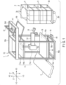
- FIG. 1 is a perspective view showing a transfer apparatus 1 according to one embodiment along with a roll-box-pallet 2 and a transport table 3.
- the transfer apparatus 1, the roll-box-pallet 2 and the transport table 3 are arranged along an X axis.
- the transfer apparatus 1 is an automatic unloader.
- the roll-box-pallet 2 is located on the front side of the transfer apparatus 1 (on the positive (+) side of the X axis of the transfer apparatus 1), and the transport table 3 is located on the rear side of the transfer apparatus 1 (on the negative (-) side of the X axis of the transfer apparatus 1).
- the roll-box-pallet 2 has a bottom floor 2a, side plates 2c and wheels 2d.
- the side plates 2c are attached to three surfaces of the four side surfaces of the roll-box-pallet 2.
- the roll-box-pallet 2 is movable.
- the transfer apparatus 1 and the transport table 3 are arranged on the ground.
- the transfer apparatus 1 may be movable.
- box-shaped packages 5 such as packed cardboard boxes are loaded in the roll-box-pallet 2 as grip target objects.
- the packages 5 may be loaded not in the roll-box-pallet 2 but on flat pallets, etc.
- the transfer apparatus 1 transfers the packages 5 loaded in the roll-box-pallet 2 to the transport table 3.
- the transfer apparatus 1 includes a housing 10, a first movement mechanism 11, an arm 12, a grip mechanism 13, a movement conveyor 15, a second movement mechanism 16, a first sensor 17, a second sensor 18, and a support bar 19.
- the housing 10 has a base portion 10a, a ceiling portion 10b, pillar portions 10c, and an appentice portion 10d.
- Each of the base portion 10a and the ceiling portion 10b includes extension portions extending along the X axis and extension portions extending along a Y axis which is perpendicular to the X axis.
- the ceiling portion 10b faces the base portion 10a in a direction along a Z axis which is perpendicular to the X axis and the Y axis.
- the pillar portions 10c extend along the Z axis.
- the base portion 10a and the ceiling portion 10b are connected by the pillar portions 10c.
- the appentice portion 10d is connected to the ceiling portion 10b and is located on the positive (+) side of the X axis of the ceiling portion 10b.
- the first movement mechanism 11 has a first linear movement portion 11a, a second linear movement portion 11b, and a connection portion 11c.
- the first linear movement portion 11a is supported on the housing 10 (pillar portions 10c) such that the first linear movement portion 11a is linearly movable along the Z axis.
- the second linear movement portion 11b is supported on the first linear movement portion 11a such that the second linear movement portion 11b is linearly movable along the Y axis.
- the connection portion 11c connects the second linear movement portion 11b and the arm 12.
- the arm 12 is supported on the connection portion 11c and is extensible and contractible along the X axis.
- the grip mechanism 13 is connected to the arm 12.
- the grip mechanism 13 is an end effector.
- the means of moving the grip mechanism 13 is not limited to the present embodiment but may be variously modified.
- the movement conveyor 15 extends in a direction parallel to an X-Y plane.
- the movement conveyor 15 can move the package 5 to the negative (-) side of the X axis, and can move the package 5 to the transport table 3.
- the second movement mechanism 16 supports the movement conveyor 15.
- the second movement mechanism 16 is supported on the housing 10 (pillar portions 10c) such that the second movement mechanism 16 is linearly movable along the Z axis.
- the means of moving the movement conveyor 15 is not limited to the present embodiment but may be variously modified.
- the support bar 19 is used in a state of being hooked to the roll-box-pallet 2. As the roll-box-pallet 2 is locked by the support bar 19, the position of the roll-box-pallet 2 is fixed. Note that the support bar 19 may be used only when necessary. For example, when the position of the roll-box-pallet 2 is fixed, the wheels 2d of the roll-box-pallet 2 may be fixed by wheel clamps, etc.
- the first sensor 17 is attached to the appentice portion 10d via a hold member 51.
- the first sensor 17 is a time-of-flight (TOF) camera which executes sensing of the lower side, in other words, the negative (-) side of the Z axis.
- TOF time-of-flight
- the first sensor 17 may detect information about the package 5 from a direction different from that of the present embodiment.
- the transfer apparatus 1 can use a plurality of sensors including the first sensor 17, and information about the package 5 may be detected from a plurality of directions.
- the second sensor 18 is attached to the base portion 10a via a hold member 61.
- the second sensor 18 is a TOF camera which executes sensing of the upper side, in other words, the positive (+) side of the Z axis.
- the second sensor 18 can sense the vicinity of the gap between the movement conveyor 15 and the roll-box-pallet 2.
- the second sensor 18 By using the second sensor 18, it is possible to detect a collapse of packages in the roll-box-pallet 2. In addition, by using the second sensor 18, it is possible to detect the distance from the second sensor 18 to the bottom floor 2a and detect the distance from the second sensor 18 to the lower surface of the package 5 passing through the gap. The drive of the second movement mechanism 16 may be controlled on the basis of the information detected by the second sensor 18. Consequently, the height of the movement conveyor 15 can be adjusted to the package 5.
- FIG. 2 is a side view showing the arm 12, the grip mechanism 13, the hold mechanism 14 and the control unit 40 of the transfer apparatus 1 along with the packages 5.
- the arm 12 has a rotation fulcrum portion 12s.
- the grip mechanism 13 is connected to the rotation fulcrum portion 12s and is turnable around the rotation fulcrum portion 12s.
- the grip mechanism 13 includes a first grip portion 20 and a second grip portion 30.
- the first grip portion 20 grips a first surface 5a of the package 5.
- the second grip portion 30 maintains an angle ⁇ 1 with the first grip portion 20, and grips a second surface 5b crossing the first surface 5a of the package 5.
- the first surface 5a is the upper surface of the package 5
- the second surface 5b is a side surface facing the transfer apparatus 1 of the side surfaces of the package 5.
- the first grip portion 20 includes a first pad 21 and a first support member 22 supporting the first pad 21.
- the first pad 21 includes a first grip surface 21a which grips the first surface 5a.
- the second grip portion 30 includes a second pad 31 and a second support member 32.
- the second pad 31 includes a second grip surface 31a which grips the second surface 5b.
- the second support member 32 supports the second pad 31, moves the second pad 31 in a direction orthogonal to the second grip surface 31a, and is connected to the rotation fulcrum portion 12s together with the first support member 22.
- the direction in which the second support member 32 moves the second pad 31 is not limited to the direction orthogonal to the second grip surface 31a but may be any direction crossing the second grip surface 31a.
- the angle ⁇ 1 is an angle between the first grip surface 21a and the second grip surface 31a.
- the second supporting member 32 includes a first member 33 and a second member 34.
- the first member 33 supports the second pad 31, and moves the second pad 31 in the direction orthogonal to the second grip surface 31a.
- the direction in which the first member 33 moves the second pad 31 is not limited to the direction orthogonal to the second grip surface 31a but may be any direction crossing the second grip surface 31a.
- the second member 34 movably supports the first member 33 and is connected to the rotation fulcrum portion 12s together with the first support member 22.
- the first support member 22 and the second member 34 are integrally formed.
- the first pad 21 is a suction pad which sucks the first surface 5a
- the second pad 31 is a suction pad which sucks the second surface 5b.
- the first grip surface 21a is parallel to an X-Y plane and faces the negative (-) side of the Z axis.
- the first grip surface 21a is parallel to the first surface 5a of the package 5.
- the second grip surface 31a is parallel to a Y-Z plane and faces the positive (+) side of the X axis.
- the first member 33 moves the second pad 31 along the X axis.
- the angle ⁇ 1 is 90°.
- the configuration of the grip mechanism 13 is presented by way of example only, and is not limited to the configuration of the present embodiment but may be variously modified.
- the hold mechanism 14 holds the grip mechanism 13 in the standby position and turns the grip mechanism 13.
- the hold mechanism 14 is connected to the arm 12 and the grip mechanism 13.
- the hold mechanism 14 exerts an attractive force T on the grip mechanism 13.
- the hold mechanism 14 is connected to the first grip portion 20 of the grip mechanism 13 and exerts the attractive force T on the first grip portion 20. Consequently, the relative positional relationship between the arm 12 and the grip mechanism 13 can be maintained.
- the hold mechanism 14 can hold the grip mechanism 13 in the standby position and turn the grip mechanism 13.
- the hold mechanism 14 extends along the Z axis.
- the hold mechanism 14 is connected to a projection portion 12p facing the first support member 22 of the arm 12. Note that the first support member 22 is located between the projection portion 12p and the first member 33.
- Examples of the hold mechanism 14 are actuators such as an air cylinder and a motor, an elastic body such as a spring, and a mechanism using air pressure.
- the hold mechanism 14 can exert a repulsive force which pushes the grip mechanism 13 away from the projection portion 12p on the grip mechanism 13. Therefore, even in a state where the grip mechanism 13 is not gripping the package 5, the hold mechanism 14 can turn the grip mechanism 13.
- the hold mechanism 14 can actively turn the grip mechanism 13.
- the active method has the following characteristics. That is, the active method can select whether or not to turn the grip mechanism 13 according to the weight of the package 5 or the arrangement of the package 5.
- the hold mechanism 14 is an air cylinder.
- the transfer apparatus 1 further includes the control unit 40 which controls the drive of the hold mechanism 14.
- the control unit 40 executes first drive and second drive of the hold mechanism 14.
- the hold mechanism 14 maintains the relative positional relationship between the arm 12 and the grip mechanism 13.
- the grip mechanism 13 is supported on the rotation fulcrum portion 12s such that the grip mechanism 13 is turnable between the standby position and an inclined position which is inclined with respect the standby position. Therefore, according to the first drive, the hold mechanism 14 can hold the grip mechanism 13 in the standby position, and the hold mechanism 14 can hold the grip mechanism 13 in the inclined position different from the standby position and maintain the package 5 in a state of being tilted with respect to a mounting surface.
- the mounting surface means a surface on which the package 5 is mounted.
- the hold mechanism 14 turns the grip mechanism 13. Therefore, according to the second drive, the hold mechanism 14 can turn the grip mechanism 13 from the standby position to the inclined position, and the hold mechanism 14 can turn the grip mechanism 13 and return the grip mechanism 13 to the standby position.
- the control unit 40 sucks air from the air cylinder as the second drive and changes the direction of the force exerted on the first grip portion 20. Consequently, the control unit 40 can turn the grip mechanism 13 at an intended timing and tilt the package 5 with respect to the mounting surface.
- the timing for turning the grip mechanism 13 may be the same as the timing for lifting the package 5 or may be after the timing for lifting the package 5.
- the hold mechanism 14 is configured not to turn the grip mechanism 13 toward the projection portion 12p from the standby position.
- the transfer apparatus 1 includes a stopper which stops the grip mechanism 13 from turning toward the projection portion 12p from the standby position. Therefore, in the state shown in FIG. 2 , the grip mechanism 13 will not turn counterclockwise from the standby position around the rotation fulcrum portion 12s. Therefore, when the grip mechanism 13 is returned to the standby position, even if the grip mechanism 13 is turned counterclockwise around the rotation fulcrum portion 12s, the grip mechanism 13 can be stopped in the standby position.
- the hold mechanism 14 can passively turn the grip mechanism 13.
- the passive method has the following characteristics. That is, the passive method does not require an actuator to be controlled. Since the hold mechanism 14 is not an actuator as described above, the transfer apparatus 1 is constituted without the control unit 40. In addition, since an angle at which the grip mechanism 13 turns changes depending on the weight of the package 5, the passive method also has the following characteristics. That is, the turning angle can be used for detecting the weight of the package 5. For example, it is possible to change a speed at which the arm 12 is moved to the positive (+) side of the Z axis on the basis of the detected weight.
- the hold mechanism 14 is configured not to turn the grip mechanism 13 toward the projection portion 12p from the standby position.
- the transfer apparatus 1 includes the stopper.
- the hold mechanism 14 can hold the grip mechanism 13 in the standby position without turning the grip mechanism 13.
- the grip mechanism 13 In a state where the grip mechanism 13 grips the package 5 and the arm 12 linearly moves to the positive (+) side of the Z axis, the grip mechanism 13 cannot be held in the standby position by the attractive force T of the hold mechanism 14, and consequently, the grip mechanism 13 turns from the standby position, and the grip mechanism 13 and the hold mechanism 14 maintain the package 5 in a state of being tilted with respect to the mounting surface.
- FIG. 3 is an illustration for explaining the transfer method using the transfer apparatus 1, and is an illustration showing a state where the position of the package 5 with respect to the transfer apparatus 1 is fixed.
- the position of the roll-box-pallet 2 with respect to the transfer apparatus 1 is fixed using the support bar 19.
- the position of the movement conveyor 15 does not match the position of a third surface 5c of a package 5-1 on the Z axis.
- the package 5-1 is a package at the uppermost level and is loaded on a package 5-2.
- the third surface 5c is the lower surface of the package 5.
- the position of the movement conveyor 15 does not match the position of the first surface 5a of the package 5-2.
- the second movement mechanism 16 is driven, and the movement conveyor 15 is moved along the Z axis.
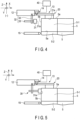
- FIG. 4 is an illustration for explaining the transfer method following FIG. 3 , and is an illustration showing a state where the height of the movement conveyor 15 of the transfer apparatus 1 is adjusted to the height of the first surface 5a of the package 5-2 of the packages 5 loaded in the roll-box-pallet 2 and the first grip portion 20 grips the first surface 5a of the package 5-1 located at the uppermost level and located on the negative (-) side of the X axis most.
- the height of the movement conveyor 15 can be adjusted to the height of the first surface 5a of the package 5-2 as shown in FIG. 4 .
- the first movement mechanism 11 and the arm 12 are driven and the grip mechanism 13 is moved.
- the grip mechanism 13 is moved, the first grip surface 21a is moved and placed above the first surface 5a of the package 5-1.
- the first grip surface 21a should preferably face the center of the first surface 5a in a direction along the Z axis. If the position of the center of gravity of the package 5 is known in advance, the first grip surface 21a should preferably face the center of gravity of the package 5 in the direction of gravity.
- the first linear movement portion 11a is driven, the grip mechanism 13 is moved to the negative (-) side of the Z axis, the first grip surface 21a is brought into contact with the first surface 5a of the package 5-1, and the first surface 5a is gripped by the first grip portion 20. In this state, the second grip surface 31a is separated from the package 5-1.
- the first member 33 moves the second pad 31 and brings the second pad 31 closer to the second surface 5b of the package 5-1.
- FIG. 5 is an illustration for explaining the transfer method following FIG. 4 , and is an illustration showing a state where the second grip portion 30 further grips the second surface 5b of the package 5-1.
- the second grip surface 31a is brought into contact with the second surface 5b of the package 5-1, and the second surface 5b is gripped by the second grip portion 30. Consequently, the grip mechanism 13 can grip the package 5-1 from two directions of the first surface 5a and the second surface 5b.
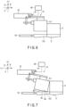
- FIG. 6 is an illustration for explaining the transfer method following FIG. 5 , and is an illustration showing a state where the package 5-1 is lifted without being tilted and the package 5-1 is floated from the package 5-2.
- the first linear movement portion 11a is driven, the grip mechanism 13 is moved to the positive (+) side of the Z axis, the package 5-1 is lifted without being tilted, and the package 5-1 is floated from the package 5-2. Subsequently, the first movement mechanism 11 and the arm 12 are driven, and the package 5 is moved and placed on the movement conveyor 15 while being maintained in a horizontal state.
- the hold mechanism 14 holds the grip mechanism 13 in the standby position. In a case where the package 5-1 cannot be dragged to the vicinity of the movement conveyor 15, it is possible to move the package 5-1 by lifting the package 5-1.
- the package 5-1 When the lifted package 5-1 is moved and placed on the movement conveyor 15, the package 5-1 may be moved in a tilted state.
- the hold mechanism 14 turns the grip mechanism 13 from the standby position and maintains the package 5 in a tilted state. More specifically, after the control unit 40 executes the second drive of the hold mechanism 14 and tilts the package 5, the control unit 40 executes the first drive of the hold mechanism 14 and maintains the package 5 in a tilted state.
- FIG. 7 is an illustration for explaining the transfer method different from that of FIG. 6 , following FIG. 5 , and is an illustration showing a state where the package 5-1 is lifted, the package 5-1 is tilted, and part of the third surface 5c of the package 5-1 is in contact with the first surface 5a of the package 5-2.
- the first linear movement portion 11a is driven, the grip mechanism 13 is moved to the positive (+) side of the Z axis, the package 5-1 is tilted with respect to the first surface 5a of the package 5-2 (the mounting surface), and part of the third surface 5c of the package 5-1 is in contact with the first surface 5a of the package 5-2 as shown in FIG. 7 .
- An angle ⁇ 2 at which the package 5-1 is tilted is not limited in particular. For example, the angle ⁇ 2 is less than or equal to 20°.
- the arm 12 is driven, and the grip mechanism 13 is moved to the negative (-) side of the X axis.
- FIG. 8 is an illustration for explaining the transfer method following FIG. 7 and is an illustration showing a state where the package 5-1 is dragged to the vicinity of the movement conveyor 15.
- the arm 12 by driving the arm 12, it is possible to drag the package 5-1 to the vicinity of the movement conveyor 15 while maintaining the package 5-1 in a tilted state. After the package 5-1 is dragged until part of the third surface 5c of the package 5-1 faces the movement conveyor 15 in a direction along the Z axis, the package 5-1 is released from a state of being gripped by the grip mechanism 13. At this time, the first linear movement portion 11a may be driven, and the grip mechanism 13 may be moved to the positive (+) side of the Z axis. In this way, it is possible to avoid a situation where the package 5-1 clashes with the grip mechanism 13 and the movement of the package 5-1 is blocked.
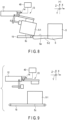
- FIG. 9 is an illustration for explaining the transfer method following FIG. 6 or FIG. 8 , and is an illustration showing a state where the package 5-1 is moved and placed on the movement conveyor 15.
- the package 5-1 can be moved and placed on the movement conveyor 15, and consequently the package 5-1 can be moved to the transport table 3.
- the movement conveyor 15 may be driven after the third surface 5c of the package 5-1 is brought into contact with the movement conveyor 15, or the movement conveyor 15 may be driven before the third surface 5c of the package 5-1 is brought into contact with the movement conveyor 15. Then, the transfer of the package 5-1 ends.
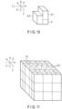
- FIG. 10 is a perspective view showing a plurality of packages 5, and is an illustration showing a state where a plurality of packages are irregularly loaded.
- the packages 5 are transferred one by one from above (from the package 5 located in the highest position). If there are a plurality of packages 5 in the highest position, the packages 5 are transferred one by one from the package 5 on the negative (-) side of the X axis (the package 5 on the transfer apparatus 1 side).
- the package 5-1 is a package located in the highest position
- the package 5-2 is located on the negative (-) side of the X axis from the package 5-1.
- the packages 5 are irregularly loaded, the height of each package 5 is not known. Therefore, in order to transfer the package 5-1, it is necessary to lift the package 5-1 under the assumption that the height of the package 5-1 is the maximum height of package specifications. For this reason, in a case where the packages are irregularly loaded, the packages 5 are lifted and transferred such that the packages 5 such as the package 5-1 will not be tilted or the packages 5 will not be dragged. For example, if the package 5-1 is tilted, the package 5-2 on the front side is knocked down, and the packages may collapse.
- FIG. 11 is another perspective view showing a plurality of packages 5, and is an illustration showing a state where a plurality of packages 5 are loaded according to a rule.
- a plurality of packages 5 are loaded in the same manner at three levels.
- the heights of the packages 5 are constant. Therefore, when the package 5 is lifted, even if the package 5 is tilted, there is no package that could fall down to the front side.
- the transfer apparatus 1 includes the arm 12 including the rotation fulcrum portion 12s, and the grip mechanism 13 which is connected to the rotation fulcrum portion and is turnable around the rotation fulcrum portion. If the package 5 is a packed cardboard box, the first surface 5a does not have sufficient strength. Therefore, if the first surface 5a of the package 5 is gripped and the second surface 5b of the package 5 is not gripped, the package (cardboard box) 5 becomes more likely to be broken while the package 5 is being lifted as the weight of the package 5 increases. Since the package 5 is lifted in a direction in which the package (cardboard box) 5 opens, the package 5 closed with an adhesive, etc., will open.
- the grip mechanism 13 includes the first grip portion 20 which grips the first surface 5a, and the second grip portion 30 which grips the second surface 5b in a state of maintaining the angle ⁇ 1.
- the grip mechanism 13 can grip the package 5 from two directions. Consequently, it is possible to transfer the package 5 without breaking the package 5. It is also possible to transfer the package 5 without dropping the package 5.
- the grip mechanism 13 is turnable and can tilt the package 5.
- the package 5 is lifted, as the package 5 is tilted, not only a direction in which the first pad 21 grips the first surface 5a (suction direction) but also a direction in which the second pad 31 grips the second surface 5b (suction direction) become not perpendicular to the direction of gravity, and as a result, the package 5 can be stably gripped.
- the grip mechanism 13 pulls the corner of the package 5, it is possible to transfer the package 5 more reliably without breaking the package 5.
- the contact area of the third surface 5c of the package 5-1 with the first surface 5a of the package 5-2, etc. can be reduced.
- frictional resistance generated on the third surface 5c can be reduced, and the package 5-1 can be smoothly dragged.
- forces exerted on the pads can be reduced, and detachment of the pads from the package 5-1 can be further suppressed.
- first surface 5a and the second surface 5b may be and whatever the material of the first surface 5a and the second surface 5b may be, it is possible to transfer the package 5 more reliably without breaking the package 5.
- the second pad 31 is movable in the direction orthogonal to the second grip surface 31a.
- the moving direction of the second pad 31 is not limited to the direction orthogonal to the second grip surface 31a but may be any direction crossing the second grip surface 31a. Therefore, after the first surface 5a is gripped by the first pad 21, the second surface 5b can be gripped by the second pad 31.
- the packages 5 of different sizes and shapes can be stably gripped by the grip mechanism 13.
- the transfer apparatus 1 which can stably transfer the package 5 can be obtained.
- the above-described embodiment is not limited to the transfer apparatus 1 but is applicable to various transfer apparatuses.
Landscapes
- Engineering & Computer Science (AREA)
- Mechanical Engineering (AREA)
- Robotics (AREA)
- Manipulator (AREA)
- De-Stacking Of Articles (AREA)
Claims (2)
- Appareil de transfert (1) comprenant :un bras (12) comprenant une partie de pivot de rotation (12s) ;un mécanisme de préhension (13) raccordé à la partie de pivot de rotation (12s) et pouvant tourner autour de la partie de pivot de rotation (12s) ;un mécanisme de maintien (14) qui est configuré pour maintenir le mécanisme de préhension (13) dans une position d'attente et est configuré pour faire tourner le mécanisme de préhension (13) ;un mécanisme de déplacement (11) qui supporte le bras (12) et est configuré pour déplacer le mécanisme de préhension (13) conjointement avec le bras (12) ; etune unité de commande (40) qui est configurée pour entraîner le mécanisme de maintien (14) selon un premier mode d'entraînement et un deuxième mode d'entraînement,caractérisé en ce que :le mécanisme de préhension (13) comprend une première partie de préhension (20) qui est configurée pour saisir une première surface (5a) d'un objet cible de préhension (5), et une deuxième partie de préhension (30) qui est configurée pour saisir une deuxième surface (5b) traversant la première surface (5a) de l'objet cible de préhension (5),la première partie de préhension (20) comprend un premier tampon (21) comprenant une première surface de préhension (21a) qui est configurée pour saisir la première surface (5a) et un premier élément de support (22) qui supporte le premier tampon (21),la deuxième partie de préhension (30) comprend un deuxième tampon (31) comprenant une deuxième surface de préhension (31a) qui est configurée pour saisir la deuxième surface (5b) et un deuxième élément de support (32) qui supporte le deuxième tampon (31), est configuré pour déplacer le deuxième tampon (31) dans une direction traversant la deuxième surface de préhension (31a) et est raccordé à la partie de pivot de rotation (12s) conjointement avec le premier élément de support (22),le mécanisme de préhension (13) est supporté sur la partie de pivot de rotation (12s), de sorte que le mécanisme de préhension (13) peut tourner entre la position d'attente et une position inclinée qui est inclinée par rapport à la position d'attente,le mécanisme de maintien (14) est fixé, séparément, au bras (12) et au premier élément de support (22),le mécanisme de maintien (14) coupe perpendiculairement le premier élément de support (22) dans la position d'attente,le mécanisme de maintien (14) est configuré pour maintenir une relation de position relative entre le bras (12) et le mécanisme de préhension (13) selon le premier mode d'entraînement, et le mécanisme de maintien (14) est configuré pour faire tourner le mécanisme de préhension (13) selon le deuxième mode d'entraînement, etlorsque l'objet cible de préhension (5) saisi par le mécanisme de préhension (13) est levé et déplacé par le mécanisme de déplacement (11) et le bras (12), le mécanisme de déplacement (11) et le bras (12) sont configurés pour lever l'objet cible de préhension (5),l'unité de commande (40) est configurée pour entraîner le mécanisme de maintien (14) selon le deuxième mode d'entraînement, et ainsi le mécanisme de maintien (14) est configuré pour faire tourner le mécanisme de préhension (13) de la position d'attente à la position inclinée, pour incliner l'objet cible de préhension (5) par rapport à une surface de montage et amener l'objet cible de préhension (5) en contact avec la surface de montage,l'unité de commande (40) est configurée pour entraîner le mécanisme de maintien (14) selon le premier mode d'entraînement, et ainsi le mécanisme de maintien est configuré pour maintenir l'objet cible de préhension (5) dans un état dans lequel il est incliné par rapport à la surface de montage, etle mécanisme de déplacement (11) et le bras (12) sont configurés pour traîner l'objet cible de préhension (5) sur la surface de montage.
- Appareil de transfert selon la revendication 1, caractérisé en ce que :
lorsque l'objet cible de préhension (5) saisi par le mécanisme de préhension (13) est levé et déplacé par le mécanisme de déplacement (11) et le bras (12), le mécanisme de maintien (14) est configuré pour maintenir le mécanisme de préhension (13) dans la position d'attente.
Applications Claiming Priority (3)
| Application Number | Priority Date | Filing Date | Title |
|---|---|---|---|
| JP2017173506 | 2017-09-08 | ||
| JP2018157392A JP7186546B2 (ja) | 2017-09-08 | 2018-08-24 | 移載装置 |
| PCT/JP2018/032227 WO2019049772A1 (fr) | 2017-09-08 | 2018-08-30 | Dispositif de transfert |
Publications (3)
| Publication Number | Publication Date |
|---|---|
| EP3680073A1 EP3680073A1 (fr) | 2020-07-15 |
| EP3680073A4 EP3680073A4 (fr) | 2021-01-27 |
| EP3680073B1 true EP3680073B1 (fr) | 2024-09-11 |
Family
ID=65904807
Family Applications (1)
| Application Number | Title | Priority Date | Filing Date |
|---|---|---|---|
| EP18853800.3A Active EP3680073B1 (fr) | 2017-09-08 | 2018-08-30 | Dispositif de transfert |
Country Status (3)
| Country | Link |
|---|---|
| US (1) | US20200180875A1 (fr) |
| EP (1) | EP3680073B1 (fr) |
| JP (1) | JP7186546B2 (fr) |
Families Citing this family (10)
| Publication number | Priority date | Publication date | Assignee | Title |
|---|---|---|---|---|
| JP7337611B2 (ja) * | 2019-09-06 | 2023-09-04 | 株式会社東芝 | 把持装置、荷役装置、及び制御装置 |
| JP7387387B2 (ja) | 2019-10-25 | 2023-11-28 | 株式会社東芝 | 荷降し装置、及び、荷降し方法 |
| JP7346242B2 (ja) * | 2019-10-29 | 2023-09-19 | 株式会社東芝 | 保持機構、移載装置、ハンドリングロボットシステムおよび荷降ろし装置 |
| JP7107300B2 (ja) * | 2019-12-18 | 2022-07-27 | 村田機械株式会社 | 移載装置 |
| JP7599942B2 (ja) * | 2020-12-28 | 2024-12-16 | 住友重機械搬送システム株式会社 | 自動倉庫システム、自動倉庫システムの制御方法 |
| JP7698388B2 (ja) * | 2021-03-04 | 2025-06-25 | 株式会社東芝 | 荷役装置及び制御方法 |
| DE102021113583B4 (de) * | 2021-05-26 | 2023-05-17 | Premium Robotics Gmbh | Greifvorrichtung sowie eine die Greifvorrichtung aufweisende Manipulatoreinheit |
| DE102021115950A1 (de) | 2021-06-21 | 2022-12-22 | Bayerische Motoren Werke Aktiengesellschaft | Depalettiervorrichtung zum Depalettieren von aufeinander gestapelten Ladungsträgern sowie Verfahren zum Depalettieren der Ladungsträger |
| EP4137428A1 (fr) | 2021-08-19 | 2023-02-22 | Media CZ s.r.o. | Préhenseur de bord à mâchoire mécanique pour saisir et déplacer un objet plat placé horizontalement |
| CN114789463B (zh) * | 2022-06-24 | 2022-10-25 | 安徽继远软件有限公司 | 基于相邻面抓取的机械抓和机械手 |
Family Cites Families (8)
| Publication number | Priority date | Publication date | Assignee | Title |
|---|---|---|---|---|
| DE19959285B4 (de) | 1999-12-09 | 2008-01-31 | J. Schmalz Gmbh | Vakuum-Greifsystem zum Greifen eines Objekts und Handhabungsgerät zum Handhaben eines Objekts mit Hilfe eines Vakuum-Greifsystems |
| DE102006022278A1 (de) | 2006-05-11 | 2007-11-15 | Deutsche Post Ag | Greifsystem für gestapeltes Stückgut |
| DE102007052012A1 (de) | 2007-10-31 | 2009-05-07 | Grenzebach Maschinenbau Gmbh | Verfahren und Vorrichtung zum Erfassen und Umladen von Gepäckstücken |
| JP6285141B2 (ja) | 2013-10-10 | 2018-02-28 | アルトリスト株式会社 | カートンの取扱設備及び取扱方法 |
| US9498887B1 (en) * | 2014-07-24 | 2016-11-22 | X Development Llc | Two-faced linearly actuated gripper |
| EP3865254B1 (fr) | 2014-08-27 | 2025-10-22 | Intelligrated Headquarters LLC | Déchargeur de cartons robotique |
| JP6559413B2 (ja) | 2014-11-13 | 2019-08-14 | 株式会社東芝 | 移載装置及び荷物取出方法 |
| DE202015009700U1 (de) * | 2015-09-21 | 2019-04-05 | Alexander Schier | Einrichtung zum Umpacken von zu Packungseinheiten zusammengefassten Stückgütern |
-
2018
- 2018-08-24 JP JP2018157392A patent/JP7186546B2/ja active Active
- 2018-08-30 EP EP18853800.3A patent/EP3680073B1/fr active Active
-
2020
- 2020-02-19 US US16/794,307 patent/US20200180875A1/en not_active Abandoned
Also Published As
| Publication number | Publication date |
|---|---|
| EP3680073A4 (fr) | 2021-01-27 |
| JP2019048375A (ja) | 2019-03-28 |
| EP3680073A1 (fr) | 2020-07-15 |
| JP7186546B2 (ja) | 2022-12-09 |
| US20200180875A1 (en) | 2020-06-11 |
Similar Documents
| Publication | Publication Date | Title |
|---|---|---|
| EP3680073B1 (fr) | Dispositif de transfert | |
| US11702297B2 (en) | Transfer method to drag grip target object | |
| KR102709380B1 (ko) | 상자들을 팔레타이징하기 위한 로봇 및 방법 | |
| JP6559413B2 (ja) | 移載装置及び荷物取出方法 | |
| CN105584767B (zh) | 物品输送设备 | |
| CN104044139B (zh) | 机器人系统以及工件的输送方法 | |
| US20140277721A1 (en) | Robot system and method for transferring workpiece | |
| US20170106534A1 (en) | Transporter and transport method | |
| KR102727924B1 (ko) | 이송 장치 | |
| JP6056708B2 (ja) | 物品移載装置 | |
| JP2023115274A (ja) | 取出装置 | |
| JPH09131685A (ja) | ロボットのハンド装置 | |
| CN101602205A (zh) | 并联机构 | |
| JP2024031481A (ja) | 移動機械システム及び移動機械システムの制御方法 | |
| JP2021024679A (ja) | 荷役制御装置、荷役システム、およびプログラム | |
| JP6976096B2 (ja) | コンテナ把持装置 | |
| JP2023139367A (ja) | 卵容器積込みシステム | |
| JP7415538B2 (ja) | 移載装置 | |
| JP7413756B2 (ja) | 移載装置 | |
| JP2024088230A (ja) | ピッキング装置、自動倉庫システム | |
| JP7731209B2 (ja) | 自動倉庫用ピッキング装置、自動倉庫システム | |
| WO2026074517A1 (fr) | Dispositif de préhension multifonction | |
| JP2023141993A (ja) | ピッキング装置、自動倉庫システム | |
| JP2022177881A (ja) | 移動機械、移動機械のハンドおよび移動機械の制御方法 |
Legal Events
| Date | Code | Title | Description |
|---|---|---|---|
| STAA | Information on the status of an ep patent application or granted ep patent |
Free format text: STATUS: THE INTERNATIONAL PUBLICATION HAS BEEN MADE |
|
| PUAI | Public reference made under article 153(3) epc to a published international application that has entered the european phase |
Free format text: ORIGINAL CODE: 0009012 |
|
| STAA | Information on the status of an ep patent application or granted ep patent |
Free format text: STATUS: REQUEST FOR EXAMINATION WAS MADE |
|
| 17P | Request for examination filed |
Effective date: 20200303 |
|
| AK | Designated contracting states |
Kind code of ref document: A1 Designated state(s): AL AT BE BG CH CY CZ DE DK EE ES FI FR GB GR HR HU IE IS IT LI LT LU LV MC MK MT NL NO PL PT RO RS SE SI SK SM TR |
|
| AX | Request for extension of the european patent |
Extension state: BA ME |
|
| DAV | Request for validation of the european patent (deleted) | ||
| DAX | Request for extension of the european patent (deleted) | ||
| A4 | Supplementary search report drawn up and despatched |
Effective date: 20210111 |
|
| RIC1 | Information provided on ipc code assigned before grant |
Ipc: B65G 47/91 20060101ALI20201218BHEP Ipc: B65G 59/04 20060101ALI20201218BHEP Ipc: B25J 15/06 20060101AFI20201218BHEP Ipc: B65G 65/00 20060101ALN20201218BHEP Ipc: B25J 15/00 20060101ALI20201218BHEP |
|
| RIC1 | Information provided on ipc code assigned before grant |
Ipc: B65G 65/00 20060101ALN20240313BHEP Ipc: B25J 15/00 20060101ALI20240313BHEP Ipc: B65G 59/04 20060101ALI20240313BHEP Ipc: B65G 47/91 20060101ALI20240313BHEP Ipc: B25J 15/06 20060101AFI20240313BHEP |
|
| GRAP | Despatch of communication of intention to grant a patent |
Free format text: ORIGINAL CODE: EPIDOSNIGR1 |
|
| STAA | Information on the status of an ep patent application or granted ep patent |
Free format text: STATUS: GRANT OF PATENT IS INTENDED |
|
| RIC1 | Information provided on ipc code assigned before grant |
Ipc: B65G 65/00 20060101ALN20240327BHEP Ipc: B25J 9/08 20060101ALI20240327BHEP Ipc: B25J 15/00 20060101ALI20240327BHEP Ipc: B65G 59/04 20060101ALI20240327BHEP Ipc: B65G 47/91 20060101ALI20240327BHEP Ipc: B25J 15/06 20060101AFI20240327BHEP |
|
| INTG | Intention to grant announced |
Effective date: 20240422 |
|
| GRAS | Grant fee paid |
Free format text: ORIGINAL CODE: EPIDOSNIGR3 |
|
| GRAA | (expected) grant |
Free format text: ORIGINAL CODE: 0009210 |
|
| STAA | Information on the status of an ep patent application or granted ep patent |
Free format text: STATUS: THE PATENT HAS BEEN GRANTED |
|
| AK | Designated contracting states |
Kind code of ref document: B1 Designated state(s): AL AT BE BG CH CY CZ DE DK EE ES FI FR GB GR HR HU IE IS IT LI LT LU LV MC MK MT NL NO PL PT RO RS SE SI SK SM TR |
|
| REG | Reference to a national code |
Ref country code: GB Ref legal event code: FG4D |
|
| REG | Reference to a national code |
Ref country code: CH Ref legal event code: EP |
|
| REG | Reference to a national code |
Ref country code: DE Ref legal event code: R096 Ref document number: 602018074353 Country of ref document: DE |
|
| REG | Reference to a national code |
Ref country code: IE Ref legal event code: FG4D |
|
| REG | Reference to a national code |
Ref country code: LT Ref legal event code: MG9D |
|
| PG25 | Lapsed in a contracting state [announced via postgrant information from national office to epo] |
Ref country code: NO Free format text: LAPSE BECAUSE OF FAILURE TO SUBMIT A TRANSLATION OF THE DESCRIPTION OR TO PAY THE FEE WITHIN THE PRESCRIBED TIME-LIMIT Effective date: 20241211 |
|
| REG | Reference to a national code |
Ref country code: NL Ref legal event code: MP Effective date: 20240911 |
|
| PG25 | Lapsed in a contracting state [announced via postgrant information from national office to epo] |
Ref country code: GR Free format text: LAPSE BECAUSE OF FAILURE TO SUBMIT A TRANSLATION OF THE DESCRIPTION OR TO PAY THE FEE WITHIN THE PRESCRIBED TIME-LIMIT Effective date: 20241212 Ref country code: FI Free format text: LAPSE BECAUSE OF FAILURE TO SUBMIT A TRANSLATION OF THE DESCRIPTION OR TO PAY THE FEE WITHIN THE PRESCRIBED TIME-LIMIT Effective date: 20240911 |
|
| PG25 | Lapsed in a contracting state [announced via postgrant information from national office to epo] |
Ref country code: BG Free format text: LAPSE BECAUSE OF FAILURE TO SUBMIT A TRANSLATION OF THE DESCRIPTION OR TO PAY THE FEE WITHIN THE PRESCRIBED TIME-LIMIT Effective date: 20240911 |
|
| PG25 | Lapsed in a contracting state [announced via postgrant information from national office to epo] |
Ref country code: LV Free format text: LAPSE BECAUSE OF FAILURE TO SUBMIT A TRANSLATION OF THE DESCRIPTION OR TO PAY THE FEE WITHIN THE PRESCRIBED TIME-LIMIT Effective date: 20240911 |
|
| PG25 | Lapsed in a contracting state [announced via postgrant information from national office to epo] |
Ref country code: HR Free format text: LAPSE BECAUSE OF FAILURE TO SUBMIT A TRANSLATION OF THE DESCRIPTION OR TO PAY THE FEE WITHIN THE PRESCRIBED TIME-LIMIT Effective date: 20240911 |
|
| PG25 | Lapsed in a contracting state [announced via postgrant information from national office to epo] |
Ref country code: RS Free format text: LAPSE BECAUSE OF FAILURE TO SUBMIT A TRANSLATION OF THE DESCRIPTION OR TO PAY THE FEE WITHIN THE PRESCRIBED TIME-LIMIT Effective date: 20241211 Ref country code: ES Free format text: LAPSE BECAUSE OF FAILURE TO SUBMIT A TRANSLATION OF THE DESCRIPTION OR TO PAY THE FEE WITHIN THE PRESCRIBED TIME-LIMIT Effective date: 20240911 |
|
| PG25 | Lapsed in a contracting state [announced via postgrant information from national office to epo] |
Ref country code: RS Free format text: LAPSE BECAUSE OF FAILURE TO SUBMIT A TRANSLATION OF THE DESCRIPTION OR TO PAY THE FEE WITHIN THE PRESCRIBED TIME-LIMIT Effective date: 20241211 Ref country code: NO Free format text: LAPSE BECAUSE OF FAILURE TO SUBMIT A TRANSLATION OF THE DESCRIPTION OR TO PAY THE FEE WITHIN THE PRESCRIBED TIME-LIMIT Effective date: 20241211 Ref country code: LV Free format text: LAPSE BECAUSE OF FAILURE TO SUBMIT A TRANSLATION OF THE DESCRIPTION OR TO PAY THE FEE WITHIN THE PRESCRIBED TIME-LIMIT Effective date: 20240911 Ref country code: HR Free format text: LAPSE BECAUSE OF FAILURE TO SUBMIT A TRANSLATION OF THE DESCRIPTION OR TO PAY THE FEE WITHIN THE PRESCRIBED TIME-LIMIT Effective date: 20240911 Ref country code: GR Free format text: LAPSE BECAUSE OF FAILURE TO SUBMIT A TRANSLATION OF THE DESCRIPTION OR TO PAY THE FEE WITHIN THE PRESCRIBED TIME-LIMIT Effective date: 20241212 Ref country code: FI Free format text: LAPSE BECAUSE OF FAILURE TO SUBMIT A TRANSLATION OF THE DESCRIPTION OR TO PAY THE FEE WITHIN THE PRESCRIBED TIME-LIMIT Effective date: 20240911 Ref country code: ES Free format text: LAPSE BECAUSE OF FAILURE TO SUBMIT A TRANSLATION OF THE DESCRIPTION OR TO PAY THE FEE WITHIN THE PRESCRIBED TIME-LIMIT Effective date: 20240911 Ref country code: BG Free format text: LAPSE BECAUSE OF FAILURE TO SUBMIT A TRANSLATION OF THE DESCRIPTION OR TO PAY THE FEE WITHIN THE PRESCRIBED TIME-LIMIT Effective date: 20240911 |
|
| REG | Reference to a national code |
Ref country code: AT Ref legal event code: MK05 Ref document number: 1722305 Country of ref document: AT Kind code of ref document: T Effective date: 20240911 |
|
| PG25 | Lapsed in a contracting state [announced via postgrant information from national office to epo] |
Ref country code: NL Free format text: LAPSE BECAUSE OF FAILURE TO SUBMIT A TRANSLATION OF THE DESCRIPTION OR TO PAY THE FEE WITHIN THE PRESCRIBED TIME-LIMIT Effective date: 20240911 |
|
| PG25 | Lapsed in a contracting state [announced via postgrant information from national office to epo] |
Ref country code: IS Free format text: LAPSE BECAUSE OF FAILURE TO SUBMIT A TRANSLATION OF THE DESCRIPTION OR TO PAY THE FEE WITHIN THE PRESCRIBED TIME-LIMIT Effective date: 20250111 Ref country code: PT Free format text: LAPSE BECAUSE OF FAILURE TO SUBMIT A TRANSLATION OF THE DESCRIPTION OR TO PAY THE FEE WITHIN THE PRESCRIBED TIME-LIMIT Effective date: 20250113 |
|
| PG25 | Lapsed in a contracting state [announced via postgrant information from national office to epo] |
Ref country code: SM Free format text: LAPSE BECAUSE OF FAILURE TO SUBMIT A TRANSLATION OF THE DESCRIPTION OR TO PAY THE FEE WITHIN THE PRESCRIBED TIME-LIMIT Effective date: 20240911 Ref country code: RO Free format text: LAPSE BECAUSE OF FAILURE TO SUBMIT A TRANSLATION OF THE DESCRIPTION OR TO PAY THE FEE WITHIN THE PRESCRIBED TIME-LIMIT Effective date: 20240911 |
|
| PG25 | Lapsed in a contracting state [announced via postgrant information from national office to epo] |
Ref country code: EE Free format text: LAPSE BECAUSE OF FAILURE TO SUBMIT A TRANSLATION OF THE DESCRIPTION OR TO PAY THE FEE WITHIN THE PRESCRIBED TIME-LIMIT Effective date: 20240911 Ref country code: AT Free format text: LAPSE BECAUSE OF FAILURE TO SUBMIT A TRANSLATION OF THE DESCRIPTION OR TO PAY THE FEE WITHIN THE PRESCRIBED TIME-LIMIT Effective date: 20240911 |
|
| PG25 | Lapsed in a contracting state [announced via postgrant information from national office to epo] |
Ref country code: PL Free format text: LAPSE BECAUSE OF FAILURE TO SUBMIT A TRANSLATION OF THE DESCRIPTION OR TO PAY THE FEE WITHIN THE PRESCRIBED TIME-LIMIT Effective date: 20240911 Ref country code: CZ Free format text: LAPSE BECAUSE OF FAILURE TO SUBMIT A TRANSLATION OF THE DESCRIPTION OR TO PAY THE FEE WITHIN THE PRESCRIBED TIME-LIMIT Effective date: 20240911 |
|
| PG25 | Lapsed in a contracting state [announced via postgrant information from national office to epo] |
Ref country code: IT Free format text: LAPSE BECAUSE OF FAILURE TO SUBMIT A TRANSLATION OF THE DESCRIPTION OR TO PAY THE FEE WITHIN THE PRESCRIBED TIME-LIMIT Effective date: 20240911 Ref country code: SK Free format text: LAPSE BECAUSE OF FAILURE TO SUBMIT A TRANSLATION OF THE DESCRIPTION OR TO PAY THE FEE WITHIN THE PRESCRIBED TIME-LIMIT Effective date: 20240911 |
|
| REG | Reference to a national code |
Ref country code: DE Ref legal event code: R097 Ref document number: 602018074353 Country of ref document: DE |
|
| PG25 | Lapsed in a contracting state [announced via postgrant information from national office to epo] |
Ref country code: DK Free format text: LAPSE BECAUSE OF FAILURE TO SUBMIT A TRANSLATION OF THE DESCRIPTION OR TO PAY THE FEE WITHIN THE PRESCRIBED TIME-LIMIT Effective date: 20240911 |
|
| PLBE | No opposition filed within time limit |
Free format text: ORIGINAL CODE: 0009261 |
|
| STAA | Information on the status of an ep patent application or granted ep patent |
Free format text: STATUS: NO OPPOSITION FILED WITHIN TIME LIMIT |
|
| REG | Reference to a national code |
Ref country code: DE Ref legal event code: R081 Ref document number: 602018074353 Country of ref document: DE Owner name: KABUSHIKI KAISHA TOSHIBA, JP Free format text: FORMER OWNERS: KABUSHIKI KAISHA TOSHIBA, TOKYO, JP; TOSHIBA INFRASTRUCTURE SYSTEMS & SOLUTIONS CORPORATION, KAWASAKI-SHI, KANAGAWA, JP |
|
| 26N | No opposition filed |
Effective date: 20250612 |
|
| REG | Reference to a national code |
Ref country code: GB Ref legal event code: 732E Free format text: REGISTERED BETWEEN 20250724 AND 20250730 |
|
| PG25 | Lapsed in a contracting state [announced via postgrant information from national office to epo] |
Ref country code: SE Free format text: LAPSE BECAUSE OF FAILURE TO SUBMIT A TRANSLATION OF THE DESCRIPTION OR TO PAY THE FEE WITHIN THE PRESCRIBED TIME-LIMIT Effective date: 20240911 |
|
| PGFP | Annual fee paid to national office [announced via postgrant information from national office to epo] |
Ref country code: DE Payment date: 20250702 Year of fee payment: 8 |
|
| PGFP | Annual fee paid to national office [announced via postgrant information from national office to epo] |
Ref country code: GB Payment date: 20250703 Year of fee payment: 8 |
|
| PGFP | Annual fee paid to national office [announced via postgrant information from national office to epo] |
Ref country code: FR Payment date: 20250703 Year of fee payment: 8 |
|
| REG | Reference to a national code |
Ref country code: CH Ref legal event code: H13 Free format text: ST27 STATUS EVENT CODE: U-0-0-H10-H13 (AS PROVIDED BY THE NATIONAL OFFICE) Effective date: 20260324 |
|
| PG25 | Lapsed in a contracting state [announced via postgrant information from national office to epo] |
Ref country code: MC Free format text: LAPSE BECAUSE OF FAILURE TO SUBMIT A TRANSLATION OF THE DESCRIPTION OR TO PAY THE FEE WITHIN THE PRESCRIBED TIME-LIMIT Effective date: 20240911 |
|
| PG25 | Lapsed in a contracting state [announced via postgrant information from national office to epo] |
Ref country code: LU Free format text: LAPSE BECAUSE OF NON-PAYMENT OF DUE FEES Effective date: 20250830 |
|
| PG25 | Lapsed in a contracting state [announced via postgrant information from national office to epo] |
Ref country code: CH Free format text: LAPSE BECAUSE OF NON-PAYMENT OF DUE FEES Effective date: 20250831 |