EP2784000B1 - Élément d'extraction mis en oeuvre dans l'extraction de fluide visqueux, et procede de fabrication d'un tel element d'extraction - Google Patents
Élément d'extraction mis en oeuvre dans l'extraction de fluide visqueux, et procede de fabrication d'un tel element d'extraction Download PDFInfo
- Publication number
- EP2784000B1 EP2784000B1 EP12851900.6A EP12851900A EP2784000B1 EP 2784000 B1 EP2784000 B1 EP 2784000B1 EP 12851900 A EP12851900 A EP 12851900A EP 2784000 B1 EP2784000 B1 EP 2784000B1
- Authority
- EP
- European Patent Office
- Prior art keywords
- pour
- inorganic particles
- base member
- hydrophobic layer
- hydrophobic
- Prior art date
- Legal status (The legal status is an assumption and is not a legal conclusion. Google has not performed a legal analysis and makes no representation as to the accuracy of the status listed.)
- Not-in-force
Links
Images



Classifications
-
- B—PERFORMING OPERATIONS; TRANSPORTING
- B65—CONVEYING; PACKING; STORING; HANDLING THIN OR FILAMENTARY MATERIAL
- B65D—CONTAINERS FOR STORAGE OR TRANSPORT OF ARTICLES OR MATERIALS, e.g. BAGS, BARRELS, BOTTLES, BOXES, CANS, CARTONS, CRATES, DRUMS, JARS, TANKS, HOPPERS, FORWARDING CONTAINERS; ACCESSORIES, CLOSURES, OR FITTINGS THEREFOR; PACKAGING ELEMENTS; PACKAGES
- B65D23/00—Details of bottles or jars not otherwise provided for
- B65D23/08—Coverings or external coatings
- B65D23/0807—Coatings
- B65D23/0814—Coatings characterised by the composition of the material
-
- B—PERFORMING OPERATIONS; TRANSPORTING
- B65—CONVEYING; PACKING; STORING; HANDLING THIN OR FILAMENTARY MATERIAL
- B65D—CONTAINERS FOR STORAGE OR TRANSPORT OF ARTICLES OR MATERIALS, e.g. BAGS, BARRELS, BOTTLES, BOXES, CANS, CARTONS, CRATES, DRUMS, JARS, TANKS, HOPPERS, FORWARDING CONTAINERS; ACCESSORIES, CLOSURES, OR FITTINGS THEREFOR; PACKAGING ELEMENTS; PACKAGES
- B65D23/00—Details of bottles or jars not otherwise provided for
- B65D23/06—Integral drip catchers or drip-preventing means
- B65D23/065—Loose or loosely-attached drip catchers or drip preventing means
-
- B—PERFORMING OPERATIONS; TRANSPORTING
- B05—SPRAYING OR ATOMISING IN GENERAL; APPLYING FLUENT MATERIALS TO SURFACES, IN GENERAL
- B05D—PROCESSES FOR APPLYING FLUENT MATERIALS TO SURFACES, IN GENERAL
- B05D1/00—Processes for applying liquids or other fluent materials
- B05D1/18—Processes for applying liquids or other fluent materials performed by dipping
-
- B—PERFORMING OPERATIONS; TRANSPORTING
- B05—SPRAYING OR ATOMISING IN GENERAL; APPLYING FLUENT MATERIALS TO SURFACES, IN GENERAL
- B05D—PROCESSES FOR APPLYING FLUENT MATERIALS TO SURFACES, IN GENERAL
- B05D5/00—Processes for applying liquids or other fluent materials to surfaces to obtain special surface effects, finishes or structures
-
- B—PERFORMING OPERATIONS; TRANSPORTING
- B32—LAYERED PRODUCTS
- B32B—LAYERED PRODUCTS, i.e. PRODUCTS BUILT-UP OF STRATA OF FLAT OR NON-FLAT, e.g. CELLULAR OR HONEYCOMB, FORM
- B32B3/00—Layered products comprising a layer with external or internal discontinuities or unevennesses, or a layer of non-planar shape; Layered products comprising a layer having particular features of form
- B32B3/02—Layered products comprising a layer with external or internal discontinuities or unevennesses, or a layer of non-planar shape; Layered products comprising a layer having particular features of form characterised by features of form at particular places, e.g. in edge regions
- B32B3/08—Layered products comprising a layer with external or internal discontinuities or unevennesses, or a layer of non-planar shape; Layered products comprising a layer having particular features of form characterised by features of form at particular places, e.g. in edge regions characterised by added members at particular parts
-
- B—PERFORMING OPERATIONS; TRANSPORTING
- B32—LAYERED PRODUCTS
- B32B—LAYERED PRODUCTS, i.e. PRODUCTS BUILT-UP OF STRATA OF FLAT OR NON-FLAT, e.g. CELLULAR OR HONEYCOMB, FORM
- B32B3/00—Layered products comprising a layer with external or internal discontinuities or unevennesses, or a layer of non-planar shape; Layered products comprising a layer having particular features of form
- B32B3/02—Layered products comprising a layer with external or internal discontinuities or unevennesses, or a layer of non-planar shape; Layered products comprising a layer having particular features of form characterised by features of form at particular places, e.g. in edge regions
- B32B3/08—Layered products comprising a layer with external or internal discontinuities or unevennesses, or a layer of non-planar shape; Layered products comprising a layer having particular features of form characterised by features of form at particular places, e.g. in edge regions characterised by added members at particular parts
- B32B3/085—Layered products comprising a layer with external or internal discontinuities or unevennesses, or a layer of non-planar shape; Layered products comprising a layer having particular features of form characterised by features of form at particular places, e.g. in edge regions characterised by added members at particular parts spaced apart pieces on the surface of a layer
-
- B—PERFORMING OPERATIONS; TRANSPORTING
- B32—LAYERED PRODUCTS
- B32B—LAYERED PRODUCTS, i.e. PRODUCTS BUILT-UP OF STRATA OF FLAT OR NON-FLAT, e.g. CELLULAR OR HONEYCOMB, FORM
- B32B37/00—Methods or apparatus for laminating, e.g. by curing or by ultrasonic bonding
- B32B37/02—Methods or apparatus for laminating, e.g. by curing or by ultrasonic bonding characterised by a sequence of laminating steps, e.g. by adding new layers at consecutive laminating stations
- B32B37/025—Transfer laminating
-
- B—PERFORMING OPERATIONS; TRANSPORTING
- B32—LAYERED PRODUCTS
- B32B—LAYERED PRODUCTS, i.e. PRODUCTS BUILT-UP OF STRATA OF FLAT OR NON-FLAT, e.g. CELLULAR OR HONEYCOMB, FORM
- B32B37/00—Methods or apparatus for laminating, e.g. by curing or by ultrasonic bonding
- B32B37/14—Methods or apparatus for laminating, e.g. by curing or by ultrasonic bonding characterised by the properties of the layers
- B32B37/144—Methods or apparatus for laminating, e.g. by curing or by ultrasonic bonding characterised by the properties of the layers using layers with different mechanical or chemical conditions or properties, e.g. layers with different thermal shrinkage, layers under tension during bonding
-
- B—PERFORMING OPERATIONS; TRANSPORTING
- B32—LAYERED PRODUCTS
- B32B—LAYERED PRODUCTS, i.e. PRODUCTS BUILT-UP OF STRATA OF FLAT OR NON-FLAT, e.g. CELLULAR OR HONEYCOMB, FORM
- B32B37/00—Methods or apparatus for laminating, e.g. by curing or by ultrasonic bonding
- B32B37/14—Methods or apparatus for laminating, e.g. by curing or by ultrasonic bonding characterised by the properties of the layers
- B32B37/24—Methods or apparatus for laminating, e.g. by curing or by ultrasonic bonding characterised by the properties of the layers with at least one layer not being coherent before laminating, e.g. made up from granular material sprinkled onto a substrate
-
- B—PERFORMING OPERATIONS; TRANSPORTING
- B32—LAYERED PRODUCTS
- B32B—LAYERED PRODUCTS, i.e. PRODUCTS BUILT-UP OF STRATA OF FLAT OR NON-FLAT, e.g. CELLULAR OR HONEYCOMB, FORM
- B32B5/00—Layered products characterised by the non- homogeneity or physical structure, i.e. comprising a fibrous, filamentary, particulate or foam layer; Layered products characterised by having a layer differing constitutionally or physically in different parts
- B32B5/16—Layered products characterised by the non- homogeneity or physical structure, i.e. comprising a fibrous, filamentary, particulate or foam layer; Layered products characterised by having a layer differing constitutionally or physically in different parts characterised by features of a layer formed of particles, e.g. chips, powder or granules
-
- B—PERFORMING OPERATIONS; TRANSPORTING
- B65—CONVEYING; PACKING; STORING; HANDLING THIN OR FILAMENTARY MATERIAL
- B65D—CONTAINERS FOR STORAGE OR TRANSPORT OF ARTICLES OR MATERIALS, e.g. BAGS, BARRELS, BOTTLES, BOXES, CANS, CARTONS, CRATES, DRUMS, JARS, TANKS, HOPPERS, FORWARDING CONTAINERS; ACCESSORIES, CLOSURES, OR FITTINGS THEREFOR; PACKAGING ELEMENTS; PACKAGES
- B65D23/00—Details of bottles or jars not otherwise provided for
- B65D23/06—Integral drip catchers or drip-preventing means
-
- B—PERFORMING OPERATIONS; TRANSPORTING
- B65—CONVEYING; PACKING; STORING; HANDLING THIN OR FILAMENTARY MATERIAL
- B65D—CONTAINERS FOR STORAGE OR TRANSPORT OF ARTICLES OR MATERIALS, e.g. BAGS, BARRELS, BOTTLES, BOXES, CANS, CARTONS, CRATES, DRUMS, JARS, TANKS, HOPPERS, FORWARDING CONTAINERS; ACCESSORIES, CLOSURES, OR FITTINGS THEREFOR; PACKAGING ELEMENTS; PACKAGES
- B65D23/00—Details of bottles or jars not otherwise provided for
- B65D23/08—Coverings or external coatings
- B65D23/0807—Coatings
- B65D23/0814—Coatings characterised by the composition of the material
- B65D23/0828—Coatings characterised by the composition of the material consisting mainly of paints or lacquers
-
- B—PERFORMING OPERATIONS; TRANSPORTING
- B65—CONVEYING; PACKING; STORING; HANDLING THIN OR FILAMENTARY MATERIAL
- B65D—CONTAINERS FOR STORAGE OR TRANSPORT OF ARTICLES OR MATERIALS, e.g. BAGS, BARRELS, BOTTLES, BOXES, CANS, CARTONS, CRATES, DRUMS, JARS, TANKS, HOPPERS, FORWARDING CONTAINERS; ACCESSORIES, CLOSURES, OR FITTINGS THEREFOR; PACKAGING ELEMENTS; PACKAGES
- B65D47/00—Closures with filling and discharging, or with discharging, devices
- B65D47/40—Closures with filling and discharging, or with discharging, devices with drip catchers or drip-preventing means
-
- B—PERFORMING OPERATIONS; TRANSPORTING
- B29—WORKING OF PLASTICS; WORKING OF SUBSTANCES IN A PLASTIC STATE IN GENERAL
- B29C—SHAPING OR JOINING OF PLASTICS; SHAPING OF MATERIAL IN A PLASTIC STATE, NOT OTHERWISE PROVIDED FOR; AFTER-TREATMENT OF THE SHAPED PRODUCTS, e.g. REPAIRING
- B29C59/00—Surface shaping of articles, e.g. embossing; Apparatus therefor
- B29C59/02—Surface shaping of articles, e.g. embossing; Apparatus therefor by mechanical means, e.g. pressing
- B29C2059/028—Incorporating particles by impact in the surface, e.g. using fluid jets or explosive forces to implant particles
-
- B—PERFORMING OPERATIONS; TRANSPORTING
- B29—WORKING OF PLASTICS; WORKING OF SUBSTANCES IN A PLASTIC STATE IN GENERAL
- B29K—INDEXING SCHEME ASSOCIATED WITH SUBCLASSES B29B, B29C OR B29D, RELATING TO MOULDING MATERIALS OR TO MATERIALS FOR MOULDS, REINFORCEMENTS, FILLERS OR PREFORMED PARTS, e.g. INSERTS
- B29K2995/00—Properties of moulding materials, reinforcements, fillers, preformed parts or moulds
- B29K2995/0037—Other properties
- B29K2995/0093—Other properties hydrophobic
-
- B—PERFORMING OPERATIONS; TRANSPORTING
- B32—LAYERED PRODUCTS
- B32B—LAYERED PRODUCTS, i.e. PRODUCTS BUILT-UP OF STRATA OF FLAT OR NON-FLAT, e.g. CELLULAR OR HONEYCOMB, FORM
- B32B37/00—Methods or apparatus for laminating, e.g. by curing or by ultrasonic bonding
- B32B37/14—Methods or apparatus for laminating, e.g. by curing or by ultrasonic bonding characterised by the properties of the layers
- B32B37/24—Methods or apparatus for laminating, e.g. by curing or by ultrasonic bonding characterised by the properties of the layers with at least one layer not being coherent before laminating, e.g. made up from granular material sprinkled onto a substrate
- B32B2037/243—Coating
-
- B—PERFORMING OPERATIONS; TRANSPORTING
- B32—LAYERED PRODUCTS
- B32B—LAYERED PRODUCTS, i.e. PRODUCTS BUILT-UP OF STRATA OF FLAT OR NON-FLAT, e.g. CELLULAR OR HONEYCOMB, FORM
- B32B2307/00—Properties of the layers or laminate
- B32B2307/70—Other properties
- B32B2307/73—Hydrophobic
-
- B—PERFORMING OPERATIONS; TRANSPORTING
- B32—LAYERED PRODUCTS
- B32B—LAYERED PRODUCTS, i.e. PRODUCTS BUILT-UP OF STRATA OF FLAT OR NON-FLAT, e.g. CELLULAR OR HONEYCOMB, FORM
- B32B2311/00—Metals, their alloys or their compounds
-
- B—PERFORMING OPERATIONS; TRANSPORTING
- B32—LAYERED PRODUCTS
- B32B—LAYERED PRODUCTS, i.e. PRODUCTS BUILT-UP OF STRATA OF FLAT OR NON-FLAT, e.g. CELLULAR OR HONEYCOMB, FORM
- B32B2439/00—Containers; Receptacles
- B32B2439/40—Closed containers
- B32B2439/60—Bottles
-
- Y—GENERAL TAGGING OF NEW TECHNOLOGICAL DEVELOPMENTS; GENERAL TAGGING OF CROSS-SECTIONAL TECHNOLOGIES SPANNING OVER SEVERAL SECTIONS OF THE IPC; TECHNICAL SUBJECTS COVERED BY FORMER USPC CROSS-REFERENCE ART COLLECTIONS [XRACs] AND DIGESTS
- Y10—TECHNICAL SUBJECTS COVERED BY FORMER USPC
- Y10T—TECHNICAL SUBJECTS COVERED BY FORMER US CLASSIFICATION
- Y10T428/00—Stock material or miscellaneous articles
- Y10T428/13—Hollow or container type article [e.g., tube, vase, etc.]
Definitions
- This invention relates to a pour-out member having a pour-out port. More specifically, the invention relates to a pour-out member used for discharging liquids such as beverages and liquid seasonings or for pouring out such liquid contents, the pour-out member being, for example, a container, a cap with pour-out port, a nozzle, a spout or a container preform.
- Pour-out members having pour-out port for discharging viscous liquids such as containers, spouts fitted to caps with pour-out port, bag-like containers and paper containers, filler nozzles for filling foods, ink-jet nozzles and the like, have been widely used for a variety of kinds of applications such as industrial products, fittings for applying adhesives or solders, fittings used for experiments and equipment for inspection and medicinal uses.
- the pour-out ports of such pour-out members are made from various materials depending on the use, and many of the materials are plastics, glasses and metals.
- the containers too, can be grouped into those of plastics, glasses and metals depending on the materials from which they are made.
- the containers made from any material are in many cases in the form having a cap that is fitted to the mouth portion by screw-engagement or just being fitted thereto, featuring excellent sealing property, lending themselves well suited for containing a variety of kinds of liquids such as beverages and liquid seasonings.
- a patent document 1 proposes forming a film of tin oxide or titanium oxide on the mouth portion of the containers.
- a patent document 2 proposes depositing fine particles of a hydrophobic oxide on the surface that comes in contact with the content in the container.
- Patent Documents
- JP 2009 066945 relates to a nozzle plate that comprises a liquid repellent layer containing filler provided on the ink discharge face side of a nozzle forming member.
- JP 2001 260360 describes a nozzle plate in which a first coat layer of silica and a second coat layer of glass containing fluorine are set to the front face of the nozzle plate.
- JP 2011 079544 relates to a cap made of synthetic resin equipped with a spout, wherein a film is provided on the spout to improve its liquid draining property.
- JP 2010 254377 describes a container, wherein hydrophobic oxide fine particles having an average primary particle diameter of 3-100 nm adhere to at least part of a surface making contact with its contents.
- WO 03/076090 relates to shaping methods for producing shaped bodies with at least one surface, which has elevations formed by microparticles, by thermally shaping materials containing organic compounds by means of a shaping tool, and to shaped bodies produced in such a manner.
- a water-repellent film (hydrophobic layer) on the mouth portion of the containers is effective in preventing the liquid from creeping as is done by the above prior arts.
- the hydrophobic film that is formed on the mouth portion of the container undergoes deformation and breakage due to aging, and the water-repelling property decreases and extinguishes due to stress produced when the cap is closed, that the water-repellent film is removed to lose water-repelling property when the cap is opened and, besides, that the removed film moves and enters into the liquid content.
- an object of the present invention to provide a pour-out member having a pour-out port that maintains close adhesion to the film and that excellently sustains water-repelling property.
- Another object is to provide a pour-out fitting having, being selectively formed on the pour-out port, a stable hydrophobic layer that is not removed or broken through the repetitive use, the pour-out fitting effectively preventing the liquid from creeping.
- a further object of the present invention is to provide a method of producing a pour-out fitting having the above hydrophobic layer formed on the pour-out port.
- a pour-out member having a pour-out port through which a viscous fluid is discharged, wherein a hydrophobic layer of fine hydrophobic inorganic particles is selectively formed on an upper end surface of a base member forming said pour-out port, characterised in that an interfacial profile between said hydrophobic layer and the base member has a surface roughness Rz (JIS B-0601-2001) of not less than 0.05 ⁇ m, wherein said interfacial profile is formed by pushing the fine inorganic particles onto the upper end surface of the base member.
- the present invention provides a method of producing the pour-out member by providing a base member having a pour-out port through which a viscous fluid is discharged and fine hydrophobic inorganic particles, characterised in that the method comprises selectively pushing the fine inorganic particles onto the upper end surface of the base member forming the pour-out port in a heated condition to form a hydrophobic layer thereon.
- the pour-out member of the present invention is the upper end surface or the top surface of the base member forming the pour-out port, and an important feature resides in that a hydrophobic layer comprising fine hydrophobic inorganic particles is selectively formed on a portion that serves as the pour-out port.
- the hydrophobic layer has not been formed on the portions (e.g., inner surface side that comes in contact with the liquid content) other than the upper end surface of the base member that serves as the pour-out port. Therefore, the container having the above pour-out port is capable of effectively eliminating such a problem that the hydrophobic layer splits and enters into the liquid contained in the container despite the cap is opened and closed repetitively.
- the fine inorganic particles forming the hydrophobic layer are effectively prevented from splitting off. Namely, the hydrophobic layer is held maintaining stability and, as a result, the pour-out port shuts off the liquid sustaining the water-repelling property, and it is made possible to effectively prevent the container from being fouled with the liquid that creeps.
- the fine inorganic particles are selectively pushed in a heated state onto the upper end surface of the base member that serves as the pour-out port to selectively form the hydrophobic layer on the pour-out port (on the upper end surface).
- the work is very easy effectively avoiding an increase in the cost.
- the bottle has a cylindrical neck portion generally designated at 1 at its upper portion.
- the lower part of the neck portion is continuous to a shoulder portion 3 that curves outward.
- the shoulder portion 3 is continuous to a body portion 5, the lower end of the body portion 5 being closed with a bottom portion 7.
- a screw thread 10 is formed on the outer circumferential surface of the neck portion 1 and with which a cap engages by screw.
- a circumferential protuberance 11 is formed under the screw thread 10.
- a TE band is provided at the lower end of the cap that is fitted by screw, and engages with the circumferential protuberance 11 creating evidence that it has not been tampered. If the cap is opened, the TE band remains on the container side being separated away from the cap letting general consumers to know that the cap was once opened.
- a support ring 13 of a large diameter is formed at the lowermost part of the neck portion 1.
- the bottle which is the pour-out member can be held and carried by utilizing the support ring 13.
- the above cylindrical neck portion 1 forms a pour-out portion having an opening for pouring out the liquid content.
- a hydrophobic layer of fine inorganic particles 20 having hydrophobic property is selectively formed on an upper end surface (top surface) 1a of the neck portion 1. That is, no hydrophobic layer is formed on the inner surface side that comes in contact with the liquid content, and no fine inorganic particle 20 is present thereon. This effectively prevents such a problem that the hydrophobic layer splits off and enters into the solution contained in the container even when the cap is opened and closed repetitively.
- the hydrophobic layer is formed in a manner of pushing the fine inorganic particles 20 into the upper end surface 1a of the neck portion 1. Therefore, even if the cap is opened and closed many times repetitively, the fine inorganic particles 20 forming the hydrophobic layer are more effectively suppressed from splitting off; i.e., the hydrophobic layer is held maintaining stability preventing the liquid from creeping out of the 1 pour-out port 1a over extended periods of time.
- the fine inorganic particles 20 without having been pushed onto the upper end surface 1a tend to easily split off when the cap is opened. Even if the fine inorganic particles 20 have not been split off toward the liquid in the container, it becomes difficult to maintain the effect for preventing the creeping of liquid when the liquid content is poured out by tilting the container.
- the fine inorganic particles 20 that form the hydrophobic layer for preventing the creeping of liquid may be those particles imparted with hydrophobic property by the surface treatment.
- the fine inorganic particles 20 are in many cases those of an oxide such as at least one of silica (silicon dioxide), alumina or titania. From the standpoint of forming a dense hydrophobic layer, further, it is desired that the fine inorganic particles 20 have a primary particle size in a range of 3 to 200 nm and, specifically, 3 to 100 nm. In the invention, what is most desirably used is a fine silica (e. g. , fumed silica) treated on the surfaces thereof with the silane coupling agent.
- silica e. g. , fumed silica
- the primary particle size is an average diameter of the primary particles measured by using a transmission type electron microscope.
- the hydrophobic layer formed from the fine inorganic particles 20 may be stretching up to a curved portion on the peripheral edge of the pour-out port (upper end surface of the neck portion 1).
- polyester as represented by polyethylene terephthalate (PET), and polyolefins such as polyethylene and polypropylene that have heretofore been used for forming the containers and, specifically, for forming containers for containing liquids.
- a gas-barrier resin such as ethylene vinyl alcohol resin and an oxygen-absorbing agent (oxidizing resin or transition metal catalyst) in combination to form a multi-layer structure.
- the mouth portion 1 is formed from the polyester such as PET.
- Fig. 1 shows an example of when the invention is applied to a plastic bottle to which only, however, the invention is in no way limited.
- the pour-out member having a pour-out port is not only limited to such containers as bottles, but also may be a filler nozzle or a spout fitted to bag-like containers, paper containers or bags for intravenous drip, or may be a spray nozzle, an ink-jet nozzle or an applying means.
- a resin layer may be formed on at least a portion that becomes the pour-out port of a nozzle made of a plastic material, a glass or a metal, and a hydrophobic layer of fine inorganic particles 20 may be selectively formed on the resin layer on the portion that becomes the pour-out port.
- the hydrophobic layer can be formed on the pour-out port of not only the plastic bottles but also of the containers of paper or metal according to the present invention.
- the hydrophobic layer of the fine inorganic particles 20 can also be formed on the pour-out port that becomes the upper end of the pour-out means even when a plastic pour-out means is fixed by fitting to the pour-out port made from the glass, paper or metal and the liquid content is poured out through the pour-out means.
- the containers are not limited to the bottles only but may also be wide-mouthed bottles or bags.
- the pour-out member having the hydrophobic layer mentioned above is typically produced as described below.
- a preform 50 as shown in Fig. 4 is formed.
- the preform can be formed by the compression forming or the injection forming that has been known per se.
- the preform is formed by the compression forming in a manner of continuously extruding a molten plastic material for forming the container by using an extruder, cutting the melt thereof by using a cutting means (cutter) of a resin feeder to obtain a molten resin mass (drop) which is a precursor for forming the preform in a molten state, holding the molten resin mass by a holding means (holder), throwing the molten resin mass into a cavity mold of a compression-forming machine through a guide means (throat), and compression-forming the molten resin mass in a core mold followed by cooling to solidify it.
- a cutting means (cutter) of a resin feeder to obtain a molten resin mass (drop) which is a precursor for forming the preform in a molten state
- holding the molten resin mass by a holding means (holder), throwing the molten resin mass into a cavity mold of a compression-forming machine through a guide means (throat), and compression-forming the molten resin
- the preform is to be formed by the injection forming
- the injection conditions there is no particular limitation on the injection conditions.
- a preform having bottom is formed at an injection temperature of 260 to 300°C and under an injection pressure of 30 to 60 kg/cm 2 .
- the preform 50 that is formed as described above is forming the neck portion 1 of a form as shown in Fig. 1 .
- the hydrophobic layer is formed on the preform 50 by using the fine inorganic particles 20 to impart water-repelling property thereto.
- a jig 60 is provided for forming the hydrophobic layer.
- the jig 60 is made from a rigid metal or the like, and is forming a dent 63 of a size which permits the insertion of the upper end portion of the mouth portion 1 of the preform 5.
- a powder of the fine inorganic particles 20 is filled or laid in the dent 63 of the jig 60. In this state, the fine inorganic particles 20 in the dent 63 are heated.
- the preform 50 which is erected upside down is lowered so that the neck portion 1 thereof enters into the dent 63 in a state where the fine inorganic particles 20 have been heated, and is pushed thereto with a predetermined pressure.
- the pushing can be easily done by using a known device such as air cylinder or cam device.
- the fine inorganic particles 20 are selectively pushed into the upper end surface 1a to selectively form the hydrophobic layer on the upper end surface 1a.
- a coating solution is prepared in which the fine inorganic particles have been dispersed, and is applied by dipping, spraying or by using a brush followed by drying to form the hydrophobic layer on the upper end surface 1a.
- the hydrophobic layer is easily to be formed on other portions, too, in addition to the upper end surface 1a as the coating solution creeps.
- the hydrophobic layer that is formed on the portions other than the upper end surface 1a may split off and may enter into the liquid content contained in the container and may lose water-repelling property.
- the hydrophobic layer can also be formed without directly filling the jig with the powder of the fine inorganic particles.
- the hydrophobic layer is formed on a film by applying a coating material containing the fine inorganic particles onto a biaxially stretched PET film followed by drying. Next, the film is arranged on a jig having a flat upper surface, the jig and the film are heated, and the preform is pushed thereon with a predetermined pressure. This method, too, makes it possible to form the hydrophobic layer to which water-repelling property is imparted.
- the film-like or rolled material for forming the layer of the fine inorganic particles there can be used the above-mentioned plastic materials such as biaxially stretched PET and biaxially stretched polypropylene, as well as metals such as aluminum and steel.
- the material may be suitably selected by taking into consideration the hardness of the base material (object product) on which the hydrophobic layer is formed and the hardness of the film-like material at a working temperature.
- the above heating may be attained by either incorporating a heater or the like in the jig 60 or by selectively heating the fine inorganic particles 20 in the dent 63 from the exterior by such means as high-frequency heating or ultrasonic oscillation.
- the heating temperature is such that the fine inorganic particles 20 are pushed into the upper end surface 1a of the neck portion 1 of the preform 50 that is pushed, and may be suitably determined depending on the kind and properties of the plastic material forming the neck portion 1.
- the heating temperature is, for example, about 40 to about 140°C if the neck portion 1 is formed from an amorphous PET.
- the preform 50 having the hydrophobic layer formed as described above is stretch-blow formed to obtain a container of the form of a bottle as shown in Fig. 1 .
- the preform 50 Prior to conducting the stretch-blow forming, the preform 50 is, as required, preheated up to a temperature suited for being stretched by such means as hot air, infrared-ray heater or high-frequency induction heating.
- a temperature suited for being stretched by such means as hot air, infrared-ray heater or high-frequency induction heating.
- the temperature in the case of the PET resin lies in a range of 85 to 130°C and, specifically, 100 to 120°C.
- the fine inorganic particles 20 are press-adhered onto the upper end portion of the mouth portion 1 of the preform 50 as described above. Thereafter, the fine inorganic particles 20 adhering to the portions other than the upper end surface 1a of the mouth portion 1 are removed therefrom by blowing the air. Thus the hydrophobic layer of the fine inorganic particles 20 is selectively formed on the upper end surface 1a.
- the preform 50 is fed into a known stretch-blow-forming machine, set in a metal mold, drawn and stretched in the axial direction by pushing a stretch rod therein, and is stretch-formed in the circumferential direction by blowing a fluid therein.
- the metal mold temperature is, usually, in a range of room temperature to 230°C.
- the metal mold temperature is desirably set at 120 to 180°C.
- the stretching ratio of the finally obtained PET resin container is, desirably, 1.5 to 25 times in terms of the area ratio.
- the stretching ratio in the axial direction is 1.2 to 6 times
- the stretching ratio in the circumferential direction is 1.2 to 4.5 times.
- the hydrophobic layer was formed on the preform 50. It is, however, also allowable to form the hydrophobic layer on a container formed from the preform 50 in the same manner as described above.
- the hydrophobic layer can be formed in the same manner as described above in a state where the pour-out portion is being fitted.
- the present invention exhibits excellent effects on account of the following fact. Namely, upon pushing in the fine inorganic particles 20, the resin layer and the hydrophobic layer are adhered together more closely and, besides, the hydrophobic layer has a rigid structure. This is presumed to be that upon pushing the fine inorganic particles themselves into the resin layer which is the base member, the interface becomes ambiguous between the resin layer and the hydrophobic layer contributing to improving the adhesion therebetween and, as a result, enabling the hydrophobic layer to acquire a rigid structure as will also be understood from the measurement of an interfacial profile between the hydrophobic layer and the base member described in Examples appearing later. In particular, a surface roughness Rz (JIS B-0601-2001) of not less than 0.05 ⁇ m is possessed by the interfacial profile between the base material and the hydrophobic layer formed by pushing in the inorganic particles 20.
- a surface roughness Rz JIS B-0601-2001
- the interface is clearly separated between the resin layer and the hydrophobic layer. Namely, it is considered that the adhesiveness is so small that the fine inorganic particles forming the hydrophobic layer easily peal and split off.
- the interfacial profile has a surface roughness which is smaller than 0.05 ⁇ m.
- the above rigid structure is formed over a wide range by providing a film on which fine inorganic particles are deposited, press-adhering the film onto the base material by using rolls so that the fine inorganic particles are transferred onto the base member to thereby form the hydrophobic layer on the surface of the base member over a wide area thereof.
- Described below are examples of the layer constitution of when the hydrophobic layer is formed on the inner surface of a bag-like container.
- Olefin layer/aluminum layer/olefin layer/hydrophobic layer Olefin layer/aluminum layer/olefin layer/hydrophobic layer
- Olefin layer/EVOH layer/olefin layer/hydrophobic layer Olefin layer/EVOH layer/olefin layer/hydrophobic layer.
- the present invention makes it possible to effectively prevent the liquid from creeping when the liquid content is to be poured out. It is, therefore, desired to so select the form of the container and the liquid contained therein that the advantage of preventing the liquid creeping can be most utilized.
- the liquid contents may be those having low viscosities through up to those having high viscosities without any limitation
- the container of the present invention is, specifically, desired as a container for containing non-carbonated beverages. That is, the carbonated beverage contains the carbonic acid dissolved therein and is, therefore, so filled as to leave some degree of head space of volume.
- the non-carbonated beverage on the other hand, is filled to an almost full capacity without leaving head space.
- the liquid starts to be poured out in a state where the container is tilted only slightly (container is assuming a nearly erected state) permitting the liquid to creep very easily.
- the present invention makes it possible to effectively prevent the liquid from creeping even in the initial period of pouring out the non-carbonated beverages.
- the container mouth portion has been formed in white color due to the heat crystallization for imparting heat resistance.
- the liquid content may be a colored liquid such as coffee, soy sauce or a variety of juices. Therefore, the fouling becomes very conspicuous around the container mouth portion if the liquid contained therein creeps. The present invention, therefore, is very useful in such cases effectively preventing the liquid from creeping.
- the present invention is applied to the bottles that contain beverages in amounts of not less than 500 ml. Namely, with the bottles having volumes of as small as about 180 ml, the user would, in many cases, drink the content directly through the container mouth portion. As the volume of the bottles become large, however, the user would drink the content by once pouring the liquid content into a cup or the like, which gives rise to the occurrence of a problem, i.e., liquid creeping. Therefore, the present invention can be effectively applied to the bottles having large volumes, too.
- the pour-out member of the invention with reference to the containers such as bottles or the container preforms.
- the pour-out member of the present invention has a pour-out port for discharging the viscous fluid (i.e., liquids as represented by foods such as beverages).
- the present invention can also be applied to a cap with pour-out port, a spout attached to bag-like containers and paper containers, as well as such nozzles as filler nozzles and ink-jet nozzles.
- the fitted cap was opened to make sure with the eye if any matter was floating in the liquid content.
- the case where no floating matter was confirmed was evaluated to be ⁇ and the case where floating matter was confirmed was evaluated to be ⁇ .
- the samples were moved and turned by using a predetermined jig based on the data of center of gravity and tilting angle obtained by mimicking the human behavior of holding a bottle by hand and pouring it by hand, and the state of liquid creeping was observed with the eye.
- the case where the liquid content flew down to the portion where the screw thread has been formed was evaluated to be ⁇ , and the case where the liquid content did not flow down to the portion where the screw thread has been formed and has not reached there was evaluated to be ⁇ .
- the sample bottles imparted with water-repelling property by the methods of the following Examples and Comparative Examples were each filled with 480 ml of coffee heated at 85°C (viscosity at 25°C: 10 mPa ⁇ s (B-type viscometer)) as liquid content. After filled, the bottles were sealed with the polypropylene cap, and were cooled with flushing water. After cooled, the bottles were preserved for predetermined number of days in an environment maintained at 22°C 60%RH. After preserved, the cap was opened to test the liquid creeping. After the test, it was confirmed with the eye if the liquid content remained adhered on the water-repellent film on the nozzle. The case where no liquid content adhered on the water-repellent film was evaluated to be ⁇ and the case where the liquid content adhered was evaluated to be ⁇ .
- the pour-out port that was prepared was dipped in ethanol and to which ultrasonic oscillation was applied to remove the fine silica particles that had been forming the hydrophobic layer.
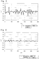
- the base member was measured for its surface roughness on a portion from where the hydrophobic layer has been removed by using a surface roughness ⁇ shape measuring apparatus (SURFCOM 2000SD3-13 manufactured by Tokyo Seimitsu Co.), and the profile thereof was regarded to be an interfacial profile between the hydrophobic layer and the base member.
- the measuring conditions were as follows:
- hinge caps with pull-ring imparted with water-repelling property by the methods of the following Examples and 500-ml polyethylene terephthalate (PET) bottles.
- PET polyethylene terephthalate
- the bottles were filled with 500 ml of soy sauce heated at 25°C as the liquid content. After filled, the bottles were sealed with the hinge cap imparted with water-repelling property.
- hinge caps with pull-ring imparted with water-repelling property by the methods of the following Examples and 500-ml polyethylene terephthalate (PET) bottles.
- PET polyethylene terephthalate
- the bottles were filled with 500 ml of soy sauce heated at 25°C as the liquid content. After filled, the bottles were sealed with the hinge cap imparted with water-repelling property.
- PET polyethylene terephthalate
- the lower mold (jig 60 for forming hydrophobic layer) an aluminum mold equipped with a band heater and having, in the upper surface thereof, a dent (recessed portion 63) of a diameter of 32 mm and a depth of 1.8 mm, and hydrophobic silica (RX300 produced by Nihon Aerosil Co.) was filled in the dent.
- the whole lower mold was heated by the band heater at 60°C.
- the upper mold there was provided an aluminum mold capable of fixing the preform.
- the formed amorphous preform was fixed thereto with the nozzle portion facing downward, and the upper mold was pressed onto the lower mold with a pressure on the working surface of 72 MPa for 3.2 seconds to press-adhere the hydrophobic silica to the top surface of the amorphous preform.
- the hydrophobic silica that has not been press-adhered was removed by blowing the air. Thereafter, the mouth portion was whitened by being crystallized by heating. Thereafter, the body portion of the preform was heated at predetermined surface temperatures from the outer side by using an infrared-ray heater and from the inner side by using a heated iron core. Thereafter, the preform was biaxially stretched by blowing to form a 500-ml stretch-blown bottle shown in Fig. 1 that was stretched roughly to 3 times longitudinally, 3 times transversely and 9 times in area.
- the metal mold temperature was set to lie in a range of 90 to 150°C.
- the air that was blown was the compressed air of room temperature (20°C). At the time of parting, the cooling air of room temperature (20°C) was introduced into the container.
- the 500-ml PET bottle having the hydrophobic silica press-adhered onto the nozzle portion thereof was tested for the adhesiveness of the film, creeping of liquid and sustenance of water-repelling property.
- the results were as shown in Table 1.
- a hydrophobic layer had been selectively formed on the upper end surface of the nozzle portion (upper end surface 1a of the pour-out portion) of the PET bottle.
- the obtained solution was applied onto one surface of a PET film of a thickness of 100 ⁇ m, and was dried in an oven heated at 100°C for 2 minutes to obtain a film coated with the hydrophobic silica.
- a water droplet that was fallen on the film did not adhere thereto despite it was a small droplet proving water-repelling property.
- a PET bottle was obtained in the same manner as in Example 1 but providing an aluminum block having a hard urethane rubber on the upper surface of the lower mold, placing the hydrophobic silica-coated film on the upper surface of the lower mold, heating the whole lower mold at 100°C and applying a pressure of 24MPa on the working surface.
- the obtained PET bottle was tested for the adhesiveness of the film, creeping of liquid and sustenance of water-repelling property. The results were as shown in Table 1.
- An amorphous preform was formed in the same manner as in Example 1. Thereafter, a bottle was blow-formed in the same manner as in Example 1 but forming a preform having a mouth portion that was whitened by crystallization by heating. With the nozzle portion facing downward, the PET bottle that was formed was dipped in the water-repelling coating solution up to the starting position of the screw thread of the bottle for 5 seconds, and was pulled up at a rate of 2 mm/min. followed by drying at room temperature for 30 minutes to obtain the PET bottle.
- the obtained PET bottle was tested for the adhesiveness of the film, creeping of liquid and sustenance of water-repelling property, and was measured for its interfacial profile. The results were as shown in Tables 1 and 2, and in Fig. 6 .
- a PET bottle was prepared in the same manner as in Example 1 but forming no hydrophobic layer.
- the obtained PET bottle was measured for its interfacial profile. The results were as shown in Table 2 and Fig. 7 . Since there has been formed no hydrophobic layer, the interfacial profile in the Reference Example represents the surface profile of the PET bottle.
- Comparative Example 1 is forming a clear interface without almost no roughness whereas Example 1 is forming an ambiguous interface having roughness.
- Example 1 it can be so comprehended that the anchoring effect is exhibited since the interface is ambiguous between the hydrophobic layer and the base member, and a strong adhesiveness is provided against the instantaneous stress at the time of opening the cap or against the stress in a period in which the cap remains closed, the water-repelling film without being broken and sustaining water-repelling property.
- Comparative Example 1 it can be so comprehended that almost no anchoring effect is exhibited since the interface is clear between the hydrophobic layer and the base member and, therefore, the water-repelling film is very weak against the stress and is broken.
- Example 1 As for the anchoring effect in Example 1, it is considered that the fine hydrophobic inorganic particles were pushed into the base member to form the hydrophobic layer, i.e., the fine hydrophobic inorganic particles were buried in the base member while reflecting the shapes of the fine inorganic particles enabling the hydrophobic layer to be formed having strength against the stress.
- the following Example deals with a case where the present invention was applied to a hinge cap with pull ring.
- the lower mold (jig 60 for forming hydrophobic layer) there was provided an aluminum mold equipped with a band heater and forming a dent (recessed portion 63) 40 mm in diameter and 1.8 mm in depth, and the dent was filled with a hydrophobic silica (R812S produced by Nihon Aerosil Co.).
- a hydrophobic silica R812S produced by Nihon Aerosil Co.
- the whole lower mold was heated at 100°C by the band heater.
- the upper mold there was provided an aluminum mold capable of fixing the hinge cap.
- the hinge cap with polyethylene pull ring was fixed to the lower mold with the pour-out portion of the hinge cap facing downward, and the upper mold was pushed onto the lower mold with a pressure of 0.1 MPa for 2 seconds to press-adhere the hydrophobic silica onto the top surface of the pour-out portion of the hinge cap.
- the hydrophobic silica that has not been press-adhered was removed by blowing the air to obtain the hinge cap with pull ring.
- the obtained hinge cap was tested for the adhesiveness of the film, creeping of liquid and sustenance of water-repelling property. The results were as shown in Table 3. It was confirmed that the hydrophobic layer had been selectively formed on the upper end surface of the pour-out portion of the hinge cap with pull ring.
- Example 1 0.007 0.034 Ref.
- Example (without hydrophobic layer) 0.008 0.037
- Adhesion of film Liquid creeping Sustenance of water repellency *1 *2 *3 *4 Ex. 3 ⁇ ⁇ ⁇ ⁇ ⁇ *1: When opened *2: After 5 times of opening and closing *3: After 10 times of opening and closing *4: After 25 times of opening and closing
Landscapes
- Engineering & Computer Science (AREA)
- Mechanical Engineering (AREA)
- Life Sciences & Earth Sciences (AREA)
- Wood Science & Technology (AREA)
- Details Of Rigid Or Semi-Rigid Containers (AREA)
- Closures For Containers (AREA)
- Containers Having Bodies Formed In One Piece (AREA)
- Packages (AREA)
Claims (10)
- Élément verseur ayant un orifice déversoir par lequel un fluide visqueux est évacué, dans lequel une couche hydrophobe de fines particules inorganiques hydrophobes [20] est formée de manière sélective sur une surface terminale supérieure [1a] d'un élément de base formant ledit orifice déversoir,
dans lequel un profil interfacial entre ladite couche hydrophobe et l'élément de base présente une rugosité superficielle Rz (JIS B-0601-2001) non inférieure à 0,05 µm, caractérisé en ce que ledit profil interfacial est formé en poussant lesdites fines particules inorganiques [20] sur ladite surface terminale supérieure [1a] dudit élément de base. - Élément verseur selon la revendication 1, dans lequel ledit élément de base se présente sous forme de récipient, de couvercle, de buse, de bec verseur ou de préforme de récipient.
- Élément verseur selon la revendication 1, dans lequel lesdites fines particules inorganiques [20] comprennent un oxyde métallique.
- Élément verseur selon la revendication 3, dans lequel lesdites fines particules inorganiques [20] comprennent de la silice présentant une taille de grains primaires se situant dans une plage allant de 3 à 200 nm.
- Élément verseur selon la revendication 1, dans lequel ledit élément de base comprend une résine thermoplastique.
- Élément verseur selon la revendication 5, dans lequel ladite résine thermoplastique est l'un quelconque des éléments parmi : le polyéthylène, le polypropylène ou le polyéthylène téréphtalate.
- Procédé de production de l'élément verseur selon la revendication 1 en prévoyant un élément de base ayant un orifice déversoir à travers lequel un fluide visqueux est déversé et des fines particules inorganiques hydrophobes [20], caractérisé en ce que le procédé comprend la poussée sélective desdites fines particules inorganiques [20] sur la surface terminale supérieure [1a] de l'élément de base formant ledit orifice déversoir à l'état chauffé pour former une couche hydrophobe sur celle-ci.
- Procédé de production selon la revendication 7, dans lequel ladite couche hydrophobe est formée au moyen d'un élément de transfert sur lequel une couche de transfert desdites fines particules inorganiques hydrophobes [20] a été formée et par la poussée de ladite couche de transfert sur la surface terminale supérieure [1a] dudit élément de base avec une pression prédéterminée de manière à ce que ladite couche de transfert soit transférée sur ladite surface terminale supérieure [1a].
- Procédé de production selon la revendication 7, dans lequel ledit élément de base se présente sous forme d'un récipient en plastique, d'un couvercle, d'une buse ou d'une préforme de récipient.
- Procédé de production selon la revendication 7, dans lequel lesdites fines particules inorganiques [20] sont poussées de manière sélective au moyen d'un gabarit [60] présentant, formé à la surface de celui-ci, une brèche [63] dans laquelle la partie terminale supérieure [1] dudit élément de base peut être insérée, en plaçant une poudre desdites fines particules inorganiques [20] dans la brèche [63] dudit gabarit [60] sous forme de couche, en insérant la partie terminale supérieure [1] dudit élément de base dans ladite brèche [63] dans un état où les fines particules inorganiques [20] placées à l'intérieur de celle-ci sont chauffées, et en poussant la surface terminale supérieure [1a] dudit élément de base sur ladite brèche [63].
Applications Claiming Priority (2)
| Application Number | Priority Date | Filing Date | Title |
|---|---|---|---|
| JP2011254415 | 2011-11-21 | ||
| PCT/JP2012/080236 WO2013077380A1 (fr) | 2011-11-21 | 2012-11-21 | Élément d'extraction mis en œuvre dans l'extraction de fluide visqueux |
Publications (3)
| Publication Number | Publication Date |
|---|---|
| EP2784000A1 EP2784000A1 (fr) | 2014-10-01 |
| EP2784000A4 EP2784000A4 (fr) | 2015-08-26 |
| EP2784000B1 true EP2784000B1 (fr) | 2017-06-14 |
Family
ID=48469822
Family Applications (1)
| Application Number | Title | Priority Date | Filing Date |
|---|---|---|---|
| EP12851900.6A Not-in-force EP2784000B1 (fr) | 2011-11-21 | 2012-11-21 | Élément d'extraction mis en oeuvre dans l'extraction de fluide visqueux, et procede de fabrication d'un tel element d'extraction |
Country Status (6)
| Country | Link |
|---|---|
| US (1) | US9580207B2 (fr) |
| EP (1) | EP2784000B1 (fr) |
| JP (1) | JP6277720B2 (fr) |
| KR (1) | KR20140105480A (fr) |
| CN (1) | CN104066654B (fr) |
| WO (1) | WO2013077380A1 (fr) |
Families Citing this family (13)
| Publication number | Priority date | Publication date | Assignee | Title |
|---|---|---|---|---|
| KR101660886B1 (ko) * | 2012-07-13 | 2016-09-28 | 도요세이칸 그룹 홀딩스 가부시키가이샤 | 내용물에 대한 미끄러짐성이 뛰어난 포장용기 |
| JP6255748B2 (ja) * | 2013-07-02 | 2018-01-10 | 東洋製罐グループホールディングス株式会社 | 滑水性に優れた表面を有する樹脂成形体 |
| JP5673870B1 (ja) * | 2013-07-26 | 2015-02-18 | 東洋製罐グループホールディングス株式会社 | 表面に液層を有する樹脂構造体 |
| JP6273736B2 (ja) * | 2013-09-24 | 2018-02-07 | 東洋製罐グループホールディングス株式会社 | 粘稠な内容物が収容される包装容器 |
| JP5807692B2 (ja) * | 2014-02-27 | 2015-11-10 | 東洋製罐株式会社 | 液注出用プラスチック成形体 |
| EP3159165B1 (fr) * | 2014-06-20 | 2020-10-07 | Toyo Seikan Co., Ltd. | Structure avec formation de film liquide en surface, et liquide de revêtement pour formation de film liquide |
| JP6467866B2 (ja) * | 2014-10-29 | 2019-02-13 | 東洋製罐グループホールディングス株式会社 | プラスチック成形体 |
| US20160137346A1 (en) | 2014-11-18 | 2016-05-19 | Brandeis University | Drip free glass bottles and methods of making such bottles |
| JP6732372B2 (ja) * | 2016-03-28 | 2020-07-29 | 株式会社吉野工業所 | 樹脂製射出成形品及びその製造方法 |
| EP3458372B1 (fr) | 2016-05-17 | 2025-11-26 | Brandeis University | Bouteilles en verre sans goutte ayant un canal circonférentiel et procédés de fabrication et d'utilisation de telles bouteilles |
| CN105947385A (zh) * | 2016-06-24 | 2016-09-21 | 广州承天包装设计有限公司 | 一种应用于液体包装的双色或多色防伪瓶盖 |
| JPWO2018079607A1 (ja) * | 2016-10-27 | 2019-09-19 | 東洋製罐株式会社 | プラスチック成形体 |
| US11668438B2 (en) * | 2020-03-30 | 2023-06-06 | Hyundai Motor Company | Fluid charging system, nozzle device, and receptacle device |
Family Cites Families (18)
| Publication number | Priority date | Publication date | Assignee | Title |
|---|---|---|---|---|
| JPH0219261A (ja) * | 1988-06-30 | 1990-01-23 | Showa Alum Corp | 密封包装用容器 |
| JPH1024267A (ja) | 1996-07-12 | 1998-01-27 | Mitsui Eng & Shipbuild Co Ltd | 撥水性表面の形成方法 |
| JP3793610B2 (ja) | 1996-11-11 | 2006-07-05 | 大日本印刷株式会社 | 部分親水性シートの製造方法 |
| JP2000319109A (ja) * | 1999-04-30 | 2000-11-21 | Toyota Central Res & Dev Lab Inc | 抗菌材料とその製造方法 |
| JP2001097384A (ja) | 1999-09-27 | 2001-04-10 | Toyo Glass Co Ltd | ガラス容器 |
| JP2001260360A (ja) | 2000-03-22 | 2001-09-25 | Matsushita Electric Ind Co Ltd | インクジェットヘッドの製造方法 |
| DE10210666A1 (de) | 2002-03-12 | 2003-10-02 | Creavis Tech & Innovation Gmbh | Formgebungsverfahren zur Herstellung von Formkörpern mit zumindest einer Oberfläche, die selbstreinigende Eigenschaften aufweist sowie mit diesem Verfahren hergestellte Formkörper |
| JP4218948B2 (ja) * | 2002-09-24 | 2009-02-04 | コニカミノルタホールディングス株式会社 | 液体吐出装置 |
| EP1550556B1 (fr) | 2002-09-24 | 2010-02-24 | Konica Minolta Holdings, Inc. | Procede de production d'une tete distribuant du liquide du type a attraction electrostatique, procede de production d'une plaque a buses |
| JP4133787B2 (ja) * | 2003-12-17 | 2008-08-13 | Tdk株式会社 | 転写用機能性フィルム、機能性層の形成方法、及び機能性層が付与された物体 |
| US8309203B2 (en) * | 2006-07-05 | 2012-11-13 | The Procter & Gamble Company | Water-soluble substrate with resistance to dissolution prior to being immersed in water |
| CA2688335C (fr) * | 2007-05-29 | 2015-07-21 | Innova Materials, Llc | Surfaces ayant des particules et procedes associes |
| JP2009066945A (ja) | 2007-09-14 | 2009-04-02 | Ricoh Co Ltd | 液体吐出装置用ノズル板、ヘッドおよびそれを用いた液体吐出装置、方法 |
| TWI488746B (zh) | 2009-02-13 | 2015-06-21 | Toyo Aluminium Kk | 層積體及容器 |
| JP4348401B1 (ja) * | 2009-02-13 | 2009-10-21 | 東洋アルミニウム株式会社 | 蓋材 |
| JP5683827B2 (ja) | 2009-03-30 | 2015-03-11 | 東洋アルミニウム株式会社 | 非付着性容器及びその製造方法 |
| JP2011079544A (ja) * | 2009-10-07 | 2011-04-21 | Mikasa Sangyo Kk | 合成樹脂製のキャップ |
| JP2011105339A (ja) | 2009-11-17 | 2011-06-02 | Wakamoto Pharmaceutical Co Ltd | ノズルに撥水性をもたせた液体用容器 |
-
2012
- 2012-11-21 US US14/359,182 patent/US9580207B2/en active Active
- 2012-11-21 WO PCT/JP2012/080236 patent/WO2013077380A1/fr not_active Ceased
- 2012-11-21 JP JP2013545954A patent/JP6277720B2/ja active Active
- 2012-11-21 CN CN201280067485.5A patent/CN104066654B/zh not_active Expired - Fee Related
- 2012-11-21 KR KR1020147016900A patent/KR20140105480A/ko not_active Ceased
- 2012-11-21 EP EP12851900.6A patent/EP2784000B1/fr not_active Not-in-force
Non-Patent Citations (1)
| Title |
|---|
| ANONYMOUS: "Surface Roughness (JIS B 0601-2001)", 1 January 2001 (2001-01-01), INET, XP055091052, Retrieved from the Internet <URL:https://us.misumi-ec.com/pdf/press/us_12e_pr1257.pdf> [retrieved on 20131202] * |
Also Published As
| Publication number | Publication date |
|---|---|
| KR20140105480A (ko) | 2014-09-01 |
| WO2013077380A1 (fr) | 2013-05-30 |
| CN104066654B (zh) | 2016-08-24 |
| JPWO2013077380A1 (ja) | 2015-04-27 |
| JP6277720B2 (ja) | 2018-02-14 |
| US20140332570A1 (en) | 2014-11-13 |
| EP2784000A1 (fr) | 2014-10-01 |
| EP2784000A4 (fr) | 2015-08-26 |
| US9580207B2 (en) | 2017-02-28 |
| CN104066654A (zh) | 2014-09-24 |
Similar Documents
| Publication | Publication Date | Title |
|---|---|---|
| EP2784000B1 (fr) | Élément d'extraction mis en oeuvre dans l'extraction de fluide visqueux, et procede de fabrication d'un tel element d'extraction | |
| JP6438886B2 (ja) | 容器、プリフォームアセンブリ及び容器を形成するための方法及び装置 | |
| US8551589B2 (en) | Mono and multi-layer articles and extrusion methods of making the same | |
| AU2009200632B2 (en) | Biaxially drawn, blow-molded bottle and its preform | |
| JP5713154B1 (ja) | 流動性内容物に対する滑り性に優れたブロー成形容器の製造方法 | |
| TW201105484A (en) | Container, preform assembly and method and apparatus for forming containers | |
| CN113853290B (zh) | 基本上平底的聚合物小瓶及其注射拉伸吹塑成型制造方法 | |
| TW201103719A (en) | Preform and method for forming a container | |
| EP3275644B1 (fr) | Structure ayant une surface hydrophobe, et son procédé de fabrication | |
| US20150329229A1 (en) | Aseptic transfer bead for plastic containers | |
| EP3666675A1 (fr) | Récipient moulé par soufflage utilisé avec un film d'huile formé sur une surface intérieure | |
| JP2015229496A (ja) | 包装体 | |
| CN1984763A (zh) | 单层和多层制品以及制备该制品的挤出法 | |
| CA2736447A1 (fr) | Contenant en plastique ayant une structure de prise renforcee | |
| JP2010214910A (ja) | 非油性内容物用多層プラスチック容器 | |
| US20090166380A1 (en) | Container for fluid product | |
| EP2554486A1 (fr) | Emballage avec un bec verseur pour produits fluides | |
| EP3552990A1 (fr) | Emballage contenant des fluides | |
| JP5428615B2 (ja) | 内容物による着色が抑制されたプラスチック容器 | |
| EP4061595B1 (fr) | Contenant présentant une couche de revêtement | |
| CN114981053A (zh) | 具有涂层的内装袋容器 | |
| TW202335920A (zh) | 飲料容器 |
Legal Events
| Date | Code | Title | Description |
|---|---|---|---|
| PUAI | Public reference made under article 153(3) epc to a published international application that has entered the european phase |
Free format text: ORIGINAL CODE: 0009012 |
|
| 17P | Request for examination filed |
Effective date: 20140515 |
|
| AK | Designated contracting states |
Kind code of ref document: A1 Designated state(s): AL AT BE BG CH CY CZ DE DK EE ES FI FR GB GR HR HU IE IS IT LI LT LU LV MC MK MT NL NO PL PT RO RS SE SI SK SM TR |
|
| DAX | Request for extension of the european patent (deleted) | ||
| RA4 | Supplementary search report drawn up and despatched (corrected) |
Effective date: 20150723 |
|
| RIC1 | Information provided on ipc code assigned before grant |
Ipc: B65D 47/40 20060101ALI20150717BHEP Ipc: B32B 3/08 20060101ALI20150717BHEP Ipc: B32B 5/16 20060101ALI20150717BHEP Ipc: B65D 23/06 20060101AFI20150717BHEP |
|
| 17Q | First examination report despatched |
Effective date: 20160428 |
|
| GRAP | Despatch of communication of intention to grant a patent |
Free format text: ORIGINAL CODE: EPIDOSNIGR1 |
|
| STAA | Information on the status of an ep patent application or granted ep patent |
Free format text: STATUS: GRANT OF PATENT IS INTENDED |
|
| INTG | Intention to grant announced |
Effective date: 20170216 |
|
| GRAS | Grant fee paid |
Free format text: ORIGINAL CODE: EPIDOSNIGR3 |
|
| GRAA | (expected) grant |
Free format text: ORIGINAL CODE: 0009210 |
|
| STAA | Information on the status of an ep patent application or granted ep patent |
Free format text: STATUS: THE PATENT HAS BEEN GRANTED |
|
| AK | Designated contracting states |
Kind code of ref document: B1 Designated state(s): AL AT BE BG CH CY CZ DE DK EE ES FI FR GB GR HR HU IE IS IT LI LT LU LV MC MK MT NL NO PL PT RO RS SE SI SK SM TR |
|
| REG | Reference to a national code |
Ref country code: GB Ref legal event code: FG4D |
|
| REG | Reference to a national code |
Ref country code: AT Ref legal event code: REF Ref document number: 900728 Country of ref document: AT Kind code of ref document: T Effective date: 20170615 Ref country code: CH Ref legal event code: EP |
|
| REG | Reference to a national code |
Ref country code: IE Ref legal event code: FG4D |
|
| REG | Reference to a national code |
Ref country code: DE Ref legal event code: R096 Ref document number: 602012033541 Country of ref document: DE |
|
| REG | Reference to a national code |
Ref country code: NL Ref legal event code: MP Effective date: 20170614 |
|
| REG | Reference to a national code |
Ref country code: LT Ref legal event code: MG4D |
|
| PG25 | Lapsed in a contracting state [announced via postgrant information from national office to epo] |
Ref country code: FI Free format text: LAPSE BECAUSE OF FAILURE TO SUBMIT A TRANSLATION OF THE DESCRIPTION OR TO PAY THE FEE WITHIN THE PRESCRIBED TIME-LIMIT Effective date: 20170614 Ref country code: GR Free format text: LAPSE BECAUSE OF FAILURE TO SUBMIT A TRANSLATION OF THE DESCRIPTION OR TO PAY THE FEE WITHIN THE PRESCRIBED TIME-LIMIT Effective date: 20170915 Ref country code: LT Free format text: LAPSE BECAUSE OF FAILURE TO SUBMIT A TRANSLATION OF THE DESCRIPTION OR TO PAY THE FEE WITHIN THE PRESCRIBED TIME-LIMIT Effective date: 20170614 Ref country code: NO Free format text: LAPSE BECAUSE OF FAILURE TO SUBMIT A TRANSLATION OF THE DESCRIPTION OR TO PAY THE FEE WITHIN THE PRESCRIBED TIME-LIMIT Effective date: 20170914 Ref country code: HR Free format text: LAPSE BECAUSE OF FAILURE TO SUBMIT A TRANSLATION OF THE DESCRIPTION OR TO PAY THE FEE WITHIN THE PRESCRIBED TIME-LIMIT Effective date: 20170614 |
|
| REG | Reference to a national code |
Ref country code: AT Ref legal event code: MK05 Ref document number: 900728 Country of ref document: AT Kind code of ref document: T Effective date: 20170614 |
|
| REG | Reference to a national code |
Ref country code: FR Ref legal event code: PLFP Year of fee payment: 6 |
|
| PG25 | Lapsed in a contracting state [announced via postgrant information from national office to epo] |
Ref country code: LV Free format text: LAPSE BECAUSE OF FAILURE TO SUBMIT A TRANSLATION OF THE DESCRIPTION OR TO PAY THE FEE WITHIN THE PRESCRIBED TIME-LIMIT Effective date: 20170614 Ref country code: SE Free format text: LAPSE BECAUSE OF FAILURE TO SUBMIT A TRANSLATION OF THE DESCRIPTION OR TO PAY THE FEE WITHIN THE PRESCRIBED TIME-LIMIT Effective date: 20170614 Ref country code: BG Free format text: LAPSE BECAUSE OF FAILURE TO SUBMIT A TRANSLATION OF THE DESCRIPTION OR TO PAY THE FEE WITHIN THE PRESCRIBED TIME-LIMIT Effective date: 20170914 Ref country code: NL Free format text: LAPSE BECAUSE OF FAILURE TO SUBMIT A TRANSLATION OF THE DESCRIPTION OR TO PAY THE FEE WITHIN THE PRESCRIBED TIME-LIMIT Effective date: 20170614 Ref country code: RS Free format text: LAPSE BECAUSE OF FAILURE TO SUBMIT A TRANSLATION OF THE DESCRIPTION OR TO PAY THE FEE WITHIN THE PRESCRIBED TIME-LIMIT Effective date: 20170614 |
|
| PG25 | Lapsed in a contracting state [announced via postgrant information from national office to epo] |
Ref country code: CZ Free format text: LAPSE BECAUSE OF FAILURE TO SUBMIT A TRANSLATION OF THE DESCRIPTION OR TO PAY THE FEE WITHIN THE PRESCRIBED TIME-LIMIT Effective date: 20170614 Ref country code: SK Free format text: LAPSE BECAUSE OF FAILURE TO SUBMIT A TRANSLATION OF THE DESCRIPTION OR TO PAY THE FEE WITHIN THE PRESCRIBED TIME-LIMIT Effective date: 20170614 Ref country code: RO Free format text: LAPSE BECAUSE OF FAILURE TO SUBMIT A TRANSLATION OF THE DESCRIPTION OR TO PAY THE FEE WITHIN THE PRESCRIBED TIME-LIMIT Effective date: 20170614 Ref country code: EE Free format text: LAPSE BECAUSE OF FAILURE TO SUBMIT A TRANSLATION OF THE DESCRIPTION OR TO PAY THE FEE WITHIN THE PRESCRIBED TIME-LIMIT Effective date: 20170614 Ref country code: AT Free format text: LAPSE BECAUSE OF FAILURE TO SUBMIT A TRANSLATION OF THE DESCRIPTION OR TO PAY THE FEE WITHIN THE PRESCRIBED TIME-LIMIT Effective date: 20170614 |
|
| PG25 | Lapsed in a contracting state [announced via postgrant information from national office to epo] |
Ref country code: PL Free format text: LAPSE BECAUSE OF FAILURE TO SUBMIT A TRANSLATION OF THE DESCRIPTION OR TO PAY THE FEE WITHIN THE PRESCRIBED TIME-LIMIT Effective date: 20170614 Ref country code: IS Free format text: LAPSE BECAUSE OF FAILURE TO SUBMIT A TRANSLATION OF THE DESCRIPTION OR TO PAY THE FEE WITHIN THE PRESCRIBED TIME-LIMIT Effective date: 20171014 Ref country code: SM Free format text: LAPSE BECAUSE OF FAILURE TO SUBMIT A TRANSLATION OF THE DESCRIPTION OR TO PAY THE FEE WITHIN THE PRESCRIBED TIME-LIMIT Effective date: 20170614 Ref country code: IT Free format text: LAPSE BECAUSE OF FAILURE TO SUBMIT A TRANSLATION OF THE DESCRIPTION OR TO PAY THE FEE WITHIN THE PRESCRIBED TIME-LIMIT Effective date: 20170614 Ref country code: ES Free format text: LAPSE BECAUSE OF FAILURE TO SUBMIT A TRANSLATION OF THE DESCRIPTION OR TO PAY THE FEE WITHIN THE PRESCRIBED TIME-LIMIT Effective date: 20170614 |
|
| REG | Reference to a national code |
Ref country code: DE Ref legal event code: R097 Ref document number: 602012033541 Country of ref document: DE |
|
| PLBE | No opposition filed within time limit |
Free format text: ORIGINAL CODE: 0009261 |
|
| STAA | Information on the status of an ep patent application or granted ep patent |
Free format text: STATUS: NO OPPOSITION FILED WITHIN TIME LIMIT |
|
| PG25 | Lapsed in a contracting state [announced via postgrant information from national office to epo] |
Ref country code: DK Free format text: LAPSE BECAUSE OF FAILURE TO SUBMIT A TRANSLATION OF THE DESCRIPTION OR TO PAY THE FEE WITHIN THE PRESCRIBED TIME-LIMIT Effective date: 20170614 |
|
| 26N | No opposition filed |
Effective date: 20180315 |
|
| PG25 | Lapsed in a contracting state [announced via postgrant information from national office to epo] |
Ref country code: MC Free format text: LAPSE BECAUSE OF FAILURE TO SUBMIT A TRANSLATION OF THE DESCRIPTION OR TO PAY THE FEE WITHIN THE PRESCRIBED TIME-LIMIT Effective date: 20170614 |
|
| PG25 | Lapsed in a contracting state [announced via postgrant information from national office to epo] |
Ref country code: CH Free format text: LAPSE BECAUSE OF NON-PAYMENT OF DUE FEES Effective date: 20171130 Ref country code: LI Free format text: LAPSE BECAUSE OF NON-PAYMENT OF DUE FEES Effective date: 20171130 |
|
| PG25 | Lapsed in a contracting state [announced via postgrant information from national office to epo] |
Ref country code: SI Free format text: LAPSE BECAUSE OF FAILURE TO SUBMIT A TRANSLATION OF THE DESCRIPTION OR TO PAY THE FEE WITHIN THE PRESCRIBED TIME-LIMIT Effective date: 20170614 Ref country code: LU Free format text: LAPSE BECAUSE OF NON-PAYMENT OF DUE FEES Effective date: 20171121 |
|
| REG | Reference to a national code |
Ref country code: BE Ref legal event code: MM Effective date: 20171130 |
|
| REG | Reference to a national code |
Ref country code: IE Ref legal event code: MM4A |
|
| PG25 | Lapsed in a contracting state [announced via postgrant information from national office to epo] |
Ref country code: MT Free format text: LAPSE BECAUSE OF NON-PAYMENT OF DUE FEES Effective date: 20171121 |
|
| PG25 | Lapsed in a contracting state [announced via postgrant information from national office to epo] |
Ref country code: IE Free format text: LAPSE BECAUSE OF NON-PAYMENT OF DUE FEES Effective date: 20171121 |
|
| PG25 | Lapsed in a contracting state [announced via postgrant information from national office to epo] |
Ref country code: BE Free format text: LAPSE BECAUSE OF NON-PAYMENT OF DUE FEES Effective date: 20171130 |
|
| PG25 | Lapsed in a contracting state [announced via postgrant information from national office to epo] |
Ref country code: HU Free format text: LAPSE BECAUSE OF FAILURE TO SUBMIT A TRANSLATION OF THE DESCRIPTION OR TO PAY THE FEE WITHIN THE PRESCRIBED TIME-LIMIT; INVALID AB INITIO Effective date: 20121121 |
|
| PG25 | Lapsed in a contracting state [announced via postgrant information from national office to epo] |
Ref country code: CY Free format text: LAPSE BECAUSE OF NON-PAYMENT OF DUE FEES Effective date: 20170614 |
|
| PG25 | Lapsed in a contracting state [announced via postgrant information from national office to epo] |
Ref country code: MK Free format text: LAPSE BECAUSE OF FAILURE TO SUBMIT A TRANSLATION OF THE DESCRIPTION OR TO PAY THE FEE WITHIN THE PRESCRIBED TIME-LIMIT Effective date: 20170614 |
|
| PG25 | Lapsed in a contracting state [announced via postgrant information from national office to epo] |
Ref country code: TR Free format text: LAPSE BECAUSE OF FAILURE TO SUBMIT A TRANSLATION OF THE DESCRIPTION OR TO PAY THE FEE WITHIN THE PRESCRIBED TIME-LIMIT Effective date: 20170614 |
|
| PG25 | Lapsed in a contracting state [announced via postgrant information from national office to epo] |
Ref country code: PT Free format text: LAPSE BECAUSE OF FAILURE TO SUBMIT A TRANSLATION OF THE DESCRIPTION OR TO PAY THE FEE WITHIN THE PRESCRIBED TIME-LIMIT Effective date: 20170614 |
|
| PG25 | Lapsed in a contracting state [announced via postgrant information from national office to epo] |
Ref country code: AL Free format text: LAPSE BECAUSE OF FAILURE TO SUBMIT A TRANSLATION OF THE DESCRIPTION OR TO PAY THE FEE WITHIN THE PRESCRIBED TIME-LIMIT Effective date: 20170614 |
|
| PGFP | Annual fee paid to national office [announced via postgrant information from national office to epo] |
Ref country code: GB Payment date: 20231123 Year of fee payment: 12 |
|
| PGFP | Annual fee paid to national office [announced via postgrant information from national office to epo] |
Ref country code: FR Payment date: 20231120 Year of fee payment: 12 Ref country code: DE Payment date: 20231121 Year of fee payment: 12 |
|
| REG | Reference to a national code |
Ref country code: DE Ref legal event code: R119 Ref document number: 602012033541 Country of ref document: DE |
|
| GBPC | Gb: european patent ceased through non-payment of renewal fee |
Effective date: 20241121 |
|
| PG25 | Lapsed in a contracting state [announced via postgrant information from national office to epo] |
Ref country code: DE Free format text: LAPSE BECAUSE OF NON-PAYMENT OF DUE FEES Effective date: 20250603 |
|
| PG25 | Lapsed in a contracting state [announced via postgrant information from national office to epo] |
Ref country code: GB Free format text: LAPSE BECAUSE OF NON-PAYMENT OF DUE FEES Effective date: 20241121 |
|
| PG25 | Lapsed in a contracting state [announced via postgrant information from national office to epo] |
Ref country code: FR Free format text: LAPSE BECAUSE OF NON-PAYMENT OF DUE FEES Effective date: 20241130 |