EP2787153A2 - Système de verrouillage et de déverrouillage d'une porte coulissante - Google Patents
Système de verrouillage et de déverrouillage d'une porte coulissante Download PDFInfo
- Publication number
- EP2787153A2 EP2787153A2 EP20140001004 EP14001004A EP2787153A2 EP 2787153 A2 EP2787153 A2 EP 2787153A2 EP 20140001004 EP20140001004 EP 20140001004 EP 14001004 A EP14001004 A EP 14001004A EP 2787153 A2 EP2787153 A2 EP 2787153A2
- Authority
- EP
- European Patent Office
- Prior art keywords
- handle
- sliding door
- locking
- blocking
- blocking element
- Prior art date
- Legal status (The legal status is an assumption and is not a legal conclusion. Google has not performed a legal analysis and makes no representation as to the accuracy of the status listed.)
- Withdrawn
Links
Images



Classifications
-
- E—FIXED CONSTRUCTIONS
- E05—LOCKS; KEYS; WINDOW OR DOOR FITTINGS; SAFES
- E05B—LOCKS; ACCESSORIES THEREFOR; HANDCUFFS
- E05B47/00—Operating or controlling locks or other fastening devices by electric or magnetic means
- E05B47/0001—Operating or controlling locks or other fastening devices by electric or magnetic means with electric actuators; Constructional features thereof
-
- E—FIXED CONSTRUCTIONS
- E05—LOCKS; KEYS; WINDOW OR DOOR FITTINGS; SAFES
- E05B—LOCKS; ACCESSORIES THEREFOR; HANDCUFFS
- E05B47/00—Operating or controlling locks or other fastening devices by electric or magnetic means
- E05B47/0046—Electric or magnetic means in the striker or on the frame; Operating or controlling the striker plate
-
- E—FIXED CONSTRUCTIONS
- E05—LOCKS; KEYS; WINDOW OR DOOR FITTINGS; SAFES
- E05B—LOCKS; ACCESSORIES THEREFOR; HANDCUFFS
- E05B47/00—Operating or controlling locks or other fastening devices by electric or magnetic means
- E05B47/02—Movement of the bolt by electromagnetic means; Adaptation of locks, latches, or parts thereof, for movement of the bolt by electromagnetic means
- E05B47/026—Movement of the bolt by electromagnetic means; Adaptation of locks, latches, or parts thereof, for movement of the bolt by electromagnetic means the bolt moving rectilinearly
-
- E—FIXED CONSTRUCTIONS
- E05—LOCKS; KEYS; WINDOW OR DOOR FITTINGS; SAFES
- E05B—LOCKS; ACCESSORIES THEREFOR; HANDCUFFS
- E05B5/00—Handles completely let into the surface of the wing
-
- E—FIXED CONSTRUCTIONS
- E05—LOCKS; KEYS; WINDOW OR DOOR FITTINGS; SAFES
- E05B—LOCKS; ACCESSORIES THEREFOR; HANDCUFFS
- E05B63/00—Locks or fastenings with special structural characteristics
- E05B63/24—Arrangements in which the fastening members which engage one another are mounted respectively on the wing and the frame and are both movable, e.g. for release by moving either of them
-
- E—FIXED CONSTRUCTIONS
- E05—LOCKS; KEYS; WINDOW OR DOOR FITTINGS; SAFES
- E05B—LOCKS; ACCESSORIES THEREFOR; HANDCUFFS
- E05B65/00—Locks or fastenings for special use
- E05B65/0025—Locks or fastenings for special use for glass wings
-
- E—FIXED CONSTRUCTIONS
- E05—LOCKS; KEYS; WINDOW OR DOOR FITTINGS; SAFES
- E05B—LOCKS; ACCESSORIES THEREFOR; HANDCUFFS
- E05B65/00—Locks or fastenings for special use
- E05B65/08—Locks or fastenings for special use for sliding wings
- E05B65/0811—Locks or fastenings for special use for sliding wings the bolts pivoting about an axis perpendicular to the wings
-
- E—FIXED CONSTRUCTIONS
- E05—LOCKS; KEYS; WINDOW OR DOOR FITTINGS; SAFES
- E05B—LOCKS; ACCESSORIES THEREFOR; HANDCUFFS
- E05B65/00—Locks or fastenings for special use
- E05B65/08—Locks or fastenings for special use for sliding wings
- E05B65/0864—Locks or fastenings for special use for sliding wings the bolts sliding perpendicular to the wings
-
- E—FIXED CONSTRUCTIONS
- E05—LOCKS; KEYS; WINDOW OR DOOR FITTINGS; SAFES
- E05B—LOCKS; ACCESSORIES THEREFOR; HANDCUFFS
- E05B1/00—Knobs or handles for wings; Knobs, handles, or press buttons for locks or latches on wings
- E05B1/0084—Handles or knobs with displays, signs, labels pictures, or the like
-
- E—FIXED CONSTRUCTIONS
- E05—LOCKS; KEYS; WINDOW OR DOOR FITTINGS; SAFES
- E05B—LOCKS; ACCESSORIES THEREFOR; HANDCUFFS
- E05B47/00—Operating or controlling locks or other fastening devices by electric or magnetic means
- E05B2047/0048—Circuits, feeding, monitoring
- E05B2047/0067—Monitoring
-
- E—FIXED CONSTRUCTIONS
- E05—LOCKS; KEYS; WINDOW OR DOOR FITTINGS; SAFES
- E05B—LOCKS; ACCESSORIES THEREFOR; HANDCUFFS
- E05B47/00—Operating or controlling locks or other fastening devices by electric or magnetic means
- E05B47/06—Controlling mechanically-operated bolts by electro-magnetically-operated detents
-
- Y—GENERAL TAGGING OF NEW TECHNOLOGICAL DEVELOPMENTS; GENERAL TAGGING OF CROSS-SECTIONAL TECHNOLOGIES SPANNING OVER SEVERAL SECTIONS OF THE IPC; TECHNICAL SUBJECTS COVERED BY FORMER USPC CROSS-REFERENCE ART COLLECTIONS [XRACs] AND DIGESTS
- Y10—TECHNICAL SUBJECTS COVERED BY FORMER USPC
- Y10S—TECHNICAL SUBJECTS COVERED BY FORMER USPC CROSS-REFERENCE ART COLLECTIONS [XRACs] AND DIGESTS
- Y10S292/00—Closure fasteners
- Y10S292/46—Sliding door fasteners
-
- Y—GENERAL TAGGING OF NEW TECHNOLOGICAL DEVELOPMENTS; GENERAL TAGGING OF CROSS-SECTIONAL TECHNOLOGIES SPANNING OVER SEVERAL SECTIONS OF THE IPC; TECHNICAL SUBJECTS COVERED BY FORMER USPC CROSS-REFERENCE ART COLLECTIONS [XRACs] AND DIGESTS
- Y10—TECHNICAL SUBJECTS COVERED BY FORMER USPC
- Y10T—TECHNICAL SUBJECTS COVERED BY FORMER US CLASSIFICATION
- Y10T292/00—Closure fasteners
- Y10T292/57—Operators with knobs or handles
Definitions
- the invention relates to a system for locking and unlocking a sliding door.
- Sliding doors are known from the prior art, which are equipped with a handle to lock or unlock the sliding door via a movement of the handle.
- these handles protrude projecting out of the plane of the sliding door, whereby the user can collide with the handle.
- the overall construction for locking and unlocking the sliding door is expensive.
- the z. B. disappear completely in a wall slot in their closed position, known from the prior art handles are due to their complexity can not be used or integrated. This means that known systems for locking and unlocking the sliding door have certain dimensions, especially for thin doors with low door thickness, such. B. glass doors are not operational.
- the object of the present invention is to avoid the above-mentioned disadvantages, in particular to provide a system for locking or unlocking a sliding door, which is suitable in doors with low strength, while improving the comfort of operating said system.
- a system for locking and unlocking a sliding door with a handle which is fastened substantially flush with the sliding door, a wall side attachable, electromechanical locking mechanism having a movable locking element which is movable between an extended locking position and a retracted release position an electronic drive which is integrated in the locking mechanism and is operatively connected to the blocking element, wherein the handle between an open position and a closed position is manually movable, the handle and the locking mechanism cooperate such that in the locking position of the locking element and in the closed position the handle movement of the sliding door from a closed position in the direction of opening position is blocked and in the open position of the handle movement of the sliding door from the closed position in the direction of opening position is effected, and min at least one manually accessible sensor module, which has a defined detection range, is in data communication with the electronic drive in such a way that the blocking element can be moved into at least one of its positions via recognition of a user in the detection area.
- a significant advantage of the invention is that the handle with its mechanism, which is integrated within the sliding door, has a flat and / or narrow overall construction, which is therefore just at low door thicknesses is advantageous to use.
- the locking mechanism is arranged on the wall side, so that in particular the movable locking element is positioned movably on the wall side in order to release a movement of the sliding door depending on its position or to block a movement of the sliding door.
- the flush design of the handle favors that no protruding components are present on the sliding door.
- the system according to the invention is suitable for manually moving the sliding door out of the closed position in the direction of the opening position by means of a manual movement of the handle.
- the invention comprises that the blocking element can be brought into its respective position via the manually accessible sensor module.
- the electromechanical locking mechanism receives from the sensor module the corresponding information, in particular a signal that the user has entered the detection area, so that the blocking element can move over the electronic drive in one of its two positions.
- the sensor module can, for. B. be arranged on one side of the sliding door. It is also conceivable that in each case a sensor module is arranged on both sides of the sliding door.
- the system according to the invention has a control unit which is in signal connection with the at least one sensor module.
- the control unit gives preference to which of the two sensor modules can be addressed by the user.
- the invention may include that from the side of the sliding door from which a lock has taken place, only unlocking via the sensor module can take place.
- only authorized persons can perform an activation of the sensor module.
- an authentication query between the system according to the invention, in particular the sensor module and the user takes place before the electromachan locking mechanism is addressed in order to move the blocking element accordingly.
- the sensor module may comprise a touch sensor and / or a proximity sensor, in particular that the sensor module is designed to detect at least one defined movement pattern of the user.
- the touch sensor can, for. B. include a piezoelectric sensor, so that the sensor module can detect a touch.
- the proximity sensor can capacitively detect an approach to the sensor module.
- other sensors are conceivable to detect the user in the detection area, such as optical sensors.
- the sensor module can also be designed such that only defined movement patterns are necessary so that the locking mechanism can be activated accordingly to move the blocking element into its respective position.
- the sensor module can, for. B. be arranged on the wall side.
- the system according to the invention comprises that the sensor module is arranged on the sliding door, in particular in the vicinity of the handle.
- the system according to the invention also provides that the sensor module is integrated in the handle and / or in the locking mechanism.
- the handle is advantageously arranged in the region of the sliding door, which faces the locking mechanism, which is arranged on the wall side.
- the handle is z. B. executed with a handle that the user can operate.
- the handle can be designed as a push handle or as a rotary handle.
- the handle is arranged in a recessed grip of the handle, so that the handle is arranged almost flush, in particular flush with the sliding door.
- the system according to the invention can be designed such that the handle can be actuated on both sides of the sliding door. This means that one handle with one handle can be provided on each side of the sliding door.
- the handle between the open position and the closed position is manually movable. In the open position, the sliding door can be moved from the closed position to the open position. This means that in the open position of the handle, the locking element of the locking mechanism does not block a movement of the sliding door.
- the system can be designed such that the handle and the locking mechanism cooperate such that in the locking position of the locking element, a transfer of the handle in the open position is effected, whereby a movement of the sliding door is released from the closed position to the open position.
- the peculiarity of this embodiment is that the blocking element can remain in the blocking position in order to move the sliding door in the open position. For this purpose, it is sufficient if the handle is transferred to the open position.
- a system according to the invention comprises that the sliding door can only be moved in the opening position in the release position of the blocking element, wherein the handle must first be moved into the open position.
- a sensor electronics can be provided which detects the position of the handle, whereby the locking element is electronically movable between the locking position and the release position in dependence on the position of the handle.
- the sensor electronics has a micro-switch which can be actuated via a movement of the handle.
- the invention relates to the sensor electronics having a magnetic element, which is arranged in particular on the handle, wherein the sensor electronics has a sensor element which is suitable for detecting the position of the magnetic element.
- the sensor element is a magnetic switch or a Hall sensor.
- the handle is mechanically connected to a movable lever member which is blocked in the closed position of the handle by the blocking element in the locked position to move with the sliding door from the closed position toward the open position.
- the lever element is within the handle in the non-visible area for the user.
- the lever element can be moved by a movement of the handle from a blocking position to a release position and vice versa.
- the blocking position of the lever element the blocking element blocks a movement of the sliding door from the closed position into the open position.
- the lever element In the release position of the lever element, the lever element is so spaced from the locking element, which is in its locking position, so that a movement of the sliding door from the closed position toward the open position is possible.
- the lever element is pivotable about an axis by a movement of the handle in its respective position.
- the lever element may have a sickle-like contour on which the handle engages in its movement.
- the system according to the invention comprises that the handle has a cam, which cooperates with the sickle-like contour, so that via a movement of the cam of the handle of the cam along the slides along sickle-like contour and simultaneously moves the lever element in the blocking position and / or release position.
- the lever element on the side facing the locking element on a contact surface which engages in the closed position of the handle on the locking element when it is in the locked position, in particular contacted.
- the contact surface forms a stop for the blocking element when, in the closed position of the handle, the sliding door is moved in the direction of the opening position. Only when the blocking element is in the release position, the path for the contact surface is free to move the sliding door with the handle in the open position.
- the contact surface with the lever element forms a common component, in particular a monolithic component. Due to strength reasons, it is advantageous that the lever element is made of a metal.
- the lever element may be a metallic stamped part.
- the handle is in operative connection with the lever member, that in the open position of the handle, the lever element is out of engagement of the locking element located in the locked position, so that a movement of the sliding door from the closed position to the open position is feasible.
- the contact surface of the lever element so far away from the blocking element is located that the sliding door can be moved from the closed position to the open position.
- the system according to the invention may comprise a locking mechanism with a carrier element on which the drive is arranged, wherein the drive is in operative connection with a movable bracket.
- the carrier element serves to space-saving to arrange the electronic drive within the locking mechanism.
- the movable bracket is in operative connection with the blocking element, so that the blocking element can be simultaneously moved by means of a movement of the bow, whereby the transfer of the blocking element from the blocking position to the release position and vice versa can be realized.
- the bracket is connected to the carrier element via a cam, which is in operative connection with the drive, wherein in particular the bracket has a first guide contour and the carrier element has a second guide contour, wherein the cam is movably mounted in both guide contours , About the movement of the cam, the bracket is moved, whereby the locking element is brought into its corresponding position.
- the cam is a reliably functioning component within the locking mechanism in order to transmit noise and low-wear the force from the drive to the bracket, in particular to the blocking element.
- the guide contours on a linear course, wherein the geometric dimensions of the guide contours are tuned with the geometry of the cam so that reliably the cam can slide back and forth within the two guide contours.
- the second guide contour is aligned obliquely to the first guide contour. This causes that in the activated state of the electronic drive, the cam moves in both guide contours of the bracket or of the carrier element, wherein only the bracket moves relative to the carrier element, whereby the blocking element between its locking position and the Release position can be moved.
- the carrier element with the drive remains rigid and immovable in its position.
- the bracket can be rotatably mounted about an axis, wherein in particular the axis is arranged on the side facing away from the locking element of the bracket.
- the bracket and the support member may be pivotable together with the support member for an emergency release of the bracket. It is conceivable that the bracket and the support member are pivotable about the common axis.
- An emergency release can z. B. be necessary if in the open position of the sliding door, the blocking element is in the locked position and operation of the electronic drive to move the blocking element is not possible.
- a power failure can z. B. make an emergency release necessary.
- the user can z. B.
- the cam remains immovable in the position within the guide contours of the bracket and the support element. Subsequently, the sliding door can be moved into the closed position, since the blocking element does not cause a collision with the sliding door, in particular the handle.
- an end piece may be provided which has a bevel, which is executed in particular to the blocking element.
- This tail is designed in the form of a door latch. The function of the tail is that in case of an emergency release the sliding door can be moved in the direction of the closed position and in a defined position of the sliding door, the oblique end piece comes in contact with the blocking element located in the blocking element. Upon further movement of the sliding door in the closed position, the oblique end pushes the locking element further in the direction of release position, at the same time the bracket and the support member to pivot within the locking mechanism.
- the end piece is fastened to the lever element, which means that both components can be made of different materials.
- end piece and the lever element may be a 2-component component.
- the tail can z. B. be made of a plastic, wherein the lever member is formed of a metallic material.
- the use of an executed plastic end piece is that a low-noise interaction with the locking element is conceivable.
- An embodiment of the system according to the invention provides that the bracket locking element side has a receptacle in which the blocking element is held.
- the recording can z. B. open on one side to guide the locking element in the receptacle.
- at least one display can be provided which displays the information as to whether the blocking element is in the blocking position and / or in the release position. By means of the display, the user receives visual information about the state in which the system according to the invention is currently located, in particular to what extent the system according to the invention is in the locked state or in the unlocked state.
- the display with colors can make the corresponding information clear to the user, in particular the color can be green for the unlocked state and the color red for the locked state of the blocking mechanism.
- the Handle also has a display that indicates the information as to whether the handle is in its closed position and / or in the open position. According to the display of the blocking element and the display of the handle can work analogously with colors. It is also included in the system according to the invention that the display via numbers and / or letters and / or pictograms and / or images provides information to the user, which provides a statement regarding the locking and / or unlocking state of the sliding door, in particular the handle and / or give the locking mechanism.
- the handle is designed as a rotary handle.
- the rotary handle is advantageously also arranged in the interior of the sliding door.
- a possible mechanical Notentriegelungsschwritt be created by instead of the rotary handle an auxiliary contour is present, which is accessible from the outside.
- the auxiliary contour can be moved, whereby the same mechanical effect is achieved within the handle, as in the operation of the handle from the inside of the sliding door.
- the auxiliary contour is designed as a slot in which, for example, a coin can be inserted in order to move the slot, as a result of which the lever element arranged inside the handle is moved accordingly.
- the auxiliary contour can thus be used to achieve a mechanical emergency release from the exterior of the sliding door.
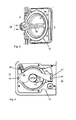
- FIG. 1 and FIG. 2 an inventive system for locking and unlocking a sliding door 1 is shown.
- FIG. 1 shows the system from the view in which the user is inside the sliding door 1.
- FIG. 2 shows the system from the view in which the user is located outside of the sliding door 1.
- a handle 10 is shown, which is part of a door fitting. The handle 10 is shown in the closed position 11. The handle 10 is located within the sliding door 1, wherein the handle 10 is arranged substantially flush with the door 1.
- the handle 10 has a handle 16 which is located in a recessed grip 24 of the handle 10.
- the handle 10 is manually movable in a clockwise direction from the closed position 11 in an open position not explicitly shown.
- FIG. 7 is illustrated that the handle 10 cooperates with a locking mechanism 30 arranged on the wall side.
- the locking mechanism 30 has an electronic drive 50, which in FIG. 12 is shown.
- the locking mechanism 30 comprises a blocking element 33, which is in FIG. 7 is in a blocking position 31, in which a movement of the sliding door 1 is blocked from its closed position 2 in the direction of opening position, which is also in FIG. 4 and FIG. 5 is shown.
- the handle 10 is according to FIG. 6 in an open position 12 movable, wherein upon rotation of the handle 10, a cam 19 acts on a sickle-like contour 20 of the lever member 13, whereby the lever member 13 is pivoted about an axis 14.
- the lever element 13 has, on the side facing the blocking element 33, a contact surface 15 which, in the closed position 11 of the handle 10, acts on the blocking element 33, which engages in FIG. 4 and FIG. 5 is shown.
- the contact surface 15 is angled in the illustrated embodiment to the remaining lever member 13, wherein the contact surface 15 is angled 90 ° to the remaining lever member 13.
- the contact surface 15 is spaced from the blocking element 33, which is in the locking position 31.
- the lever element 13 is spring-loaded, in particular that a spring element 25 acts on the lever element 13.
- a sensor electronics 34 which detects the position 11, 12 of the handle 10.
- the blocking element which here in FIG. 3 is not explicitly shown, electronically movable between the locking position 31 and the release position 32.
- the sensor electronics 34 has a magnetic element 35, which is arranged on the inside of the handle 10, in particular within the handle 12.
- the sensor electronics 34 comprise a sensor element 42 which is suitable for detecting the position of the magnetic element 35.
- the magnetic element 35 is firmly connected to the handle 12, so that upon movement of the handle 16, the magnetic element 35 is moved.
- the sensor element 42 is located on the wall side and spaced from the handle 16.
- the sensor element 42 may be a Hall sensor. It is also conceivable to form the sensor element 42 as a magnetic switch.
- the invention comprises that the sensor electronics 34 has a micro-switch on the wall side, which is actuated via a movement of the handle 10.
- the system comprises a sensor module 60 having a defined detection area to recognize a user. If the sensor module 60 has detected a user, the electronic drive 50 of the electromechanical locking mechanism 30 is activated to move the blocking element 33 in one of its two positions 31, 32.
- the sensor module 60 may include a touch sensor or a proximity sensor. In the present embodiment is located inside ( FIG. 1 ) and outside ( FIG. 2 ) Each sensor module 60, the sensor module 60 has two fields 62, 63 on.
- the field 63 is responsible for the detection of the user,
- the field 62 has a display 61, which indicates to the user the information to what extent a locking and / or unlocking of the sliding door 1 is present.
- a lock is present when the blocking element 33 is in the blocking position 31 and the handle 10 is in the closed position 11.
- An unlocking of the sliding door 1 is present when the handle 10 is in the open position 12 and the locking element 33 is still in the locking position 31 (see FIG. 6 ).
- the transfer of the handle 10 in the just-mentioned opening position 12 is done manually or by hand, in particular from the inside of the sliding door 1 and / or the outside of the sliding door 1.
- the handle 10 has an auxiliary contour 23rd according to FIG. 2 on, which is executed slit-like. Above a special tool, the auxiliary contour 23 can be moved, which z. B. is carried out in the event of an emergency release.
- An unlocking state of the sliding door 1 may also be present when the handle 10 is in the closed position 11, for example as in FIG. 4
- the locking mechanism 30 has electronically moved the blocking element 33 in the release position 32, which in FIG. 9 is shown.
- the handle 10 and the blocking element 33 can no longer collide in a movement of the sliding door 1 in the direction of the opening position 3.
- FIG. 7 the locking mechanism 30 is shown, which is disposed on the wall side within a housing 43. Indicated is the sensor module 60, which is responsible for the detection of the user, such as in FIG. 1 and FIG. 2 already described. Within the housing 43, an electronics 46 is also arranged, which may have, for example, microprocessor, control units, a board, an energy storage.
- FIG. 8 the blocking element 33 in the locking position 31, in which the sliding door 1 with the handle 10 can not be moved out of the closed position 2.
- the drive 50 is on a support member 36.
- the drive 50 may be an electric motor which is connected to a cam 44.
- the cam 44 connects the carrier element 36 with a bracket 37 spaced therefrom.
- the bracket 37 has a first guide contour 38 and the carrier element 36 has a second guide contour 39.
- Both guide contours 38, 39 are designed in the present embodiment as a slot by the cam 44 can move.
- the cam 44 in the direction of pivot axis 40 moves upward. Since the second guide contour 39 of the bracket 37 is aligned obliquely to the first guide contour 38 of the carrier element 36 (s. FIG. 8 ), pivoted the bracket 37 is in a clockwise direction about the axis 40, wherein the support member 36 immovably remains in its position.
- the bracket 38 has a receptacle 41 in which the blocking element 33 is held. Since the bracket 38 in the position according to FIG. 9 pivots, the blocking element 33 is simultaneously moved to the retracted release position 32.
- the carrier element 36 is spring-loaded by a spring 45, wherein the spring force acts to the right.
- the blocking element 33 is in the blocking position 31 and the sliding door 1 is in the open position 3. If in such a situation, for example, an electronic control of the locking mechanism 30 and the electronic drive 50 is not possible, for example, power failure, according to FIG. 10 and FIG. 11 the locking mechanism 30 are unlocked. This is done in such a way that upon movement of the sliding door in the direction of the closed position 2, the blocking element 33 is moved out of the blocking position 31 into the release position 32 due to the force of the sliding door 1.
- FIG. 10 It is shown that by the external force acting on the blocking element 33, both the bracket 37 and the support member 36 are pivoted about the axis 40 in a clockwise direction, at the same time the cam 44 remains in its position within both guide contours 38, 39.
- the lever element 13 has an end piece 21 in the region of the contact surface 15, which is formed obliquely to the blocking element 33.
- the end piece 21 is made of a plastic, wherein the lever member 30 is metallic.
- the blocking element 33 is pushed in the direction of the release position 32 in the housing 43 of the locking mechanism 30.
- FIG. 4 and FIG. 5 It is shown that the lever element 13 between a blocking position 17 and a release position 18 can be moved manually via the operation of the handle 10.
- a movement of the sliding door 1 can not take place when the blocking element 33 is in the blocking position 31. Only when the release position 32 of the locking element 33 is reached, a movement of the sliding door 1 in the direction of the open position 3 can be made, even if the lever member 13 is in the blocking position 17.
- the carrier element 36 has a stair contour, with a support surface 47 for the drive 50.
- a display 22 is provided which indicates the position 11, 12 of the handle 10.
- the display 22 may, for. B. correspond to the embodiments of the display 61 of the sensor module 60.
- the sensor module 60 is connected to an electronic drive, which is not explicitly shown, in order to effect an automatic movement of the sliding door 1 between the closed position 2 and the open position 3. Furthermore, it is conceivable that the sensor module 60 can receive commands from the user via voice recognition and process them further so that corresponding actions of the locking mechanism 30 can take place.
- the invention relates to the sliding door 1 is a door with a very low door thickness, in particular a glass door. In addition or alternatively, it is conceivable that such a system, in particular for cabin doors and / or toilet doors can be used.
Landscapes
- Physics & Mathematics (AREA)
- Electromagnetism (AREA)
- Engineering & Computer Science (AREA)
- Structural Engineering (AREA)
- Lock And Its Accessories (AREA)
Applications Claiming Priority (1)
| Application Number | Priority Date | Filing Date | Title |
|---|---|---|---|
| DE201310103316 DE102013103316A1 (de) | 2013-04-03 | 2013-04-03 | System zur Verriegelung und Entriegelung einer Schiebetür |
Publications (2)
| Publication Number | Publication Date |
|---|---|
| EP2787153A2 true EP2787153A2 (fr) | 2014-10-08 |
| EP2787153A3 EP2787153A3 (fr) | 2015-07-29 |
Family
ID=50343570
Family Applications (1)
| Application Number | Title | Priority Date | Filing Date |
|---|---|---|---|
| EP14001004.2A Withdrawn EP2787153A3 (fr) | 2013-04-03 | 2014-03-19 | Système de verrouillage et de déverrouillage d'une porte coulissante |
Country Status (4)
| Country | Link |
|---|---|
| US (1) | US20140300116A1 (fr) |
| EP (1) | EP2787153A3 (fr) |
| CN (1) | CN104100144A (fr) |
| DE (1) | DE102013103316A1 (fr) |
Cited By (3)
| Publication number | Priority date | Publication date | Assignee | Title |
|---|---|---|---|---|
| EP3312370A1 (fr) * | 2016-10-19 | 2018-04-25 | Roto Frank AG | Système de serrure pour un élément de fermeture d'un immeuble, élément de fermeture doté du système de serrure ainsi que procédé de mise en uvre d'un déverrouillage normal et un déverrouillage d'urgence |
| EP3543440A1 (fr) * | 2018-03-22 | 2019-09-25 | dormakaba Deutschland GmbH | Serrure pour porte |
| EP3532686A4 (fr) * | 2016-10-25 | 2020-07-29 | Cheng, Qianyan | Verrou de sûreté de porte de grange |
Families Citing this family (14)
| Publication number | Priority date | Publication date | Assignee | Title |
|---|---|---|---|---|
| MX355745B (es) | 2013-03-15 | 2018-04-27 | Spectrum Brands Inc | Sistema de restriccion de acceso inalambrico con antena integrada, activacion tactil y metodo de comunicacion de luz. |
| US20150059424A1 (en) * | 2013-09-04 | 2015-03-05 | Kiekert Aktiengesellschaft | Motor vehicle door |
| EP3073034B1 (fr) * | 2015-03-23 | 2019-03-13 | VKR Holding A/S | Toit ouvrant manuellement et électriquement avec un élément de verrouillage actionnable manuellement et électriquement |
| WO2017165349A1 (fr) | 2016-03-22 | 2017-09-28 | Spectrum Brands, Inc. | Dispositif d'ouverture de porte de garage à authentification par capteur tactile |
| US10604967B2 (en) | 2016-07-06 | 2020-03-31 | Capsa Solutions Llc | Bin having electronic low profile locking assembly |
| US10045900B2 (en) | 2016-07-06 | 2018-08-14 | Capsa Solutions Llc | Method for controlling access to medications |
| US11450158B2 (en) | 2018-01-05 | 2022-09-20 | Spectrum Brands, Inc. | Touch isolated electronic lock |
| CN109466192B (zh) * | 2018-06-27 | 2024-06-28 | 北京东方金鹰信息科技股份有限公司 | 锁章机构及用印机 |
| US11078693B2 (en) * | 2018-10-26 | 2021-08-03 | GM Global Technology Operations LLC | Cover for side door release handle |
| CN111775679B (zh) * | 2019-04-02 | 2024-06-11 | 杭州嘉迈机械有限公司 | 操纵驱动系统以及具有该操纵驱动系统的车辆和套件 |
| US11401735B2 (en) * | 2019-05-29 | 2022-08-02 | Jack Schonberger | Sliding door latch systems and method |
| DE202021100149U1 (de) | 2021-01-14 | 2022-04-20 | Franz Schneider Brakel Gmbh + Co Kg | Muschelgriff und Schiebe- oder Drehtür oder -fenster |
| KR102403510B1 (ko) * | 2021-02-22 | 2022-05-31 | 주식회사 노바랩스 | 차량 도어 비상 개폐 장치 |
| ES3038728T3 (en) | 2021-05-17 | 2025-10-15 | Inventio Ag | Sliding door system |
Family Cites Families (33)
| Publication number | Priority date | Publication date | Assignee | Title |
|---|---|---|---|---|
| US1583594A (en) * | 1925-09-21 | 1926-05-04 | Jackson Paul | Latch for removable panels |
| US1684980A (en) * | 1927-04-04 | 1928-09-18 | Harry J Green | Car-door lock |
| US2666319A (en) * | 1950-05-20 | 1954-01-19 | James F Price | Reversible latch and lock for slidable closure devices |
| US2807489A (en) * | 1953-10-21 | 1957-09-24 | Safe Padlock And Hardware Comp | Sliding door lock |
| US3065985A (en) * | 1961-05-25 | 1962-11-27 | Ekco Products Company | Latch unit |
| CA852079A (en) * | 1969-05-14 | 1970-09-22 | Watson George | Door lock |
| DE2325566B2 (de) * | 1973-05-19 | 1981-06-04 | Zeiss Ikon Ag Goerz-Werk, 1000 Berlin | Magnetisch/mechanisch arbeitender Schließzylinder |
| US4676537A (en) * | 1984-05-15 | 1987-06-30 | Ogden Industries Pty. Ltd. | Sliding door latch strike |
| US5615918A (en) * | 1994-12-15 | 1997-04-01 | Ferrell; W. Stuart | Glass door release system |
| US6283514B1 (en) * | 1996-08-16 | 2001-09-04 | K. A. Schmersal Gmbh & Co. | Apparatus for monitoring and controlling access to a restricted area |
| DE29705754U1 (de) * | 1997-03-18 | 1997-07-03 | Wenzel, Wolfgang, 13129 Berlin | Vandalen-Sicherheitstürverschluß für den Führerstand in Triebfahrzeugen |
| DE19805659C1 (de) * | 1998-02-12 | 1999-03-18 | Bosch Gmbh Robert | Vorrichtung zum Auslösen einer Berechtigungsabfrage für ein Fahrzeug |
| DE19917212A1 (de) * | 1999-04-16 | 2000-11-02 | Euchner Gmbh & Co | Vorrichtung zum Schalten einer Verbindung in Abhängigkeit des Zustandes einer zu überwachenden Einrichtung, insbesondere Sicherheitsschalter |
| US6032991A (en) * | 1999-04-27 | 2000-03-07 | Yeh; Tsun-Tsai | Electrically operable tubular lock |
| WO2001040606A1 (fr) * | 1999-11-29 | 2001-06-07 | Robert Bosch Gmbh | Systeme de verrouillage de portes d'automobile |
| DE10051055A1 (de) * | 2000-10-14 | 2002-05-02 | Bosch Gmbh Robert | Vorrichtung zum Einleiten eines Öffnungs- und Verriegelungsvorgangs eines Kraftfahrzeugs |
| US7126453B2 (en) * | 2001-02-21 | 2006-10-24 | Kiekert Ag | Keyless system for actuating a motor-vehicle door latch |
| DE10216225A1 (de) * | 2002-04-08 | 2003-10-30 | Euchner Gmbh & Co | Elektromagnetisches Zuhaltesystem eines Sicherheitsschalters |
| DE10232244B4 (de) * | 2002-07-17 | 2005-03-10 | Huf Huelsbeck & Fuerst Gmbh | Schließsystem für eine Tür, Klappe o. dgl., insbesondere bei Fahrzeugen |
| JP3770218B2 (ja) * | 2002-08-29 | 2006-04-26 | アイシン精機株式会社 | 車両用ドア開扉用人体検出装置及びその使用方法 |
| DE10305704B3 (de) * | 2003-02-12 | 2004-06-24 | K.A. Schmersal Gmbh & Co | Sicherheitszuhaltung |
| AT7419U1 (de) * | 2003-11-03 | 2005-03-25 | Hamberger Josef | Schloss |
| DE102005031441A1 (de) * | 2005-07-04 | 2007-01-11 | Huf Hülsbeck & Fürst Gmbh & Co. Kg | Griffvorrichtung |
| DE102006011085A1 (de) * | 2005-09-07 | 2007-03-08 | Arca Beteiligungen Gmbh | Türöffner |
| US7552954B2 (en) * | 2006-02-13 | 2009-06-30 | The Boeing Company | Storage bin latch assembly |
| SE532298C2 (sv) * | 2008-04-16 | 2009-12-08 | Jokab Safety Ab | Låsanordning |
| DE102008060004B4 (de) * | 2008-11-25 | 2021-09-02 | Pilz Gmbh & Co. Kg | Sicherheitsschalter zum Erzeugen eines Anlagenfreigabesignals in Abhängigkeit von der Position einer beweglichen Schutztür |
| US7836735B2 (en) * | 2009-01-02 | 2010-11-23 | Federal Lock Co. Ltd. | Drawer lock set |
| DE102010005926A1 (de) * | 2009-06-03 | 2010-12-09 | Dorma Gmbh + Co. Kg | Schloss, insbesondere Türschloss, mit verbesserter Schließmechanik |
| DE102010050650A1 (de) * | 2010-11-09 | 2012-05-10 | Dorma Gmbh + Co. Kg | Universelle Verriegelung für entlang eines Verfahrwegs bewegbare und schwenkbare Flügel |
| US20120192493A1 (en) * | 2011-01-28 | 2012-08-02 | Wolfe Jeffrey A | Automated strike |
| DE102011002055A1 (de) * | 2011-04-14 | 2012-10-18 | Dorma Gmbh + Co. Kg | Berührungslos betätigbare Flügelanlage |
| IL224099A (en) * | 2013-01-02 | 2014-02-27 | Gregory Orenbach | Door security lock |
-
2013
- 2013-04-03 DE DE201310103316 patent/DE102013103316A1/de not_active Withdrawn
-
2014
- 2014-03-19 EP EP14001004.2A patent/EP2787153A3/fr not_active Withdrawn
- 2014-04-02 US US14/243,375 patent/US20140300116A1/en not_active Abandoned
- 2014-04-03 CN CN201410133916.4A patent/CN104100144A/zh active Pending
Non-Patent Citations (1)
| Title |
|---|
| None |
Cited By (4)
| Publication number | Priority date | Publication date | Assignee | Title |
|---|---|---|---|---|
| EP3312370A1 (fr) * | 2016-10-19 | 2018-04-25 | Roto Frank AG | Système de serrure pour un élément de fermeture d'un immeuble, élément de fermeture doté du système de serrure ainsi que procédé de mise en uvre d'un déverrouillage normal et un déverrouillage d'urgence |
| EP3532686A4 (fr) * | 2016-10-25 | 2020-07-29 | Cheng, Qianyan | Verrou de sûreté de porte de grange |
| EP3543440A1 (fr) * | 2018-03-22 | 2019-09-25 | dormakaba Deutschland GmbH | Serrure pour porte |
| EP3901397A1 (fr) * | 2018-03-22 | 2021-10-27 | dormakaba Deutschland GmbH | Serrure pour porte |
Also Published As
| Publication number | Publication date |
|---|---|
| CN104100144A (zh) | 2014-10-15 |
| DE102013103316A1 (de) | 2014-10-09 |
| US20140300116A1 (en) | 2014-10-09 |
| EP2787153A3 (fr) | 2015-07-29 |
Similar Documents
| Publication | Publication Date | Title |
|---|---|---|
| DE102013103316A1 (de) | System zur Verriegelung und Entriegelung einer Schiebetür | |
| EP2032783A1 (fr) | Dispositif d'actionnement | |
| DE69710147T2 (de) | Betätigungsgriff zum Öffnen eines Schlosses einer Kraftfahrzeugöffnung | |
| DE102017209005A1 (de) | Verschlussverriegelung für eine hintere Fahrzeugtür mit einem Notfall-Kindersicherungs-Lösemechanismus | |
| EP1808336A1 (fr) | Dispositif de contrôle d'accès pour des véhicules à moteur | |
| EP3469175A1 (fr) | Module de poignée de portière pour véhicule à moteur | |
| DE102013100304A1 (de) | Kupplungsvorrichtung | |
| DE102007013480A1 (de) | Vorrichtung zum lösbaren Zuhalten eines verriegelten geschlossenen Zustandes einer Raumtrenneinrichtung | |
| DE102009006352A1 (de) | Lock-Box | |
| DE102016109566A1 (de) | Kraftfahrzeugtürverschluss-System | |
| EP2642049B1 (fr) | Manipulation d'un véhicule automobile doté d'un élément de recouvrement mobile | |
| EP2615227B1 (fr) | Clé à télécommande pour un véhicule automobile | |
| DE102014104143A1 (de) | Schloss für eine Tür oder ein Fenster | |
| DE102014104128B4 (de) | Zuhaltung | |
| EP3159466B1 (fr) | Dispositif de verrouillage comprenant deux corps de verrouillages mobiles | |
| DE102018124159A1 (de) | Flächenbündiger Betätigungsgriff für eine Schließvorrichtung | |
| EP1908899A2 (fr) | Système de verrouillage | |
| DE102017108752A1 (de) | Schloss mit Zuzieheinrichtung für ein Kraftfahrzeug | |
| DE102008016698B4 (de) | Schloss mit einem Selektorelement zur Umstellung der Funktionseigenschaften des Schlosses | |
| EP2738324B1 (fr) | Serrure dotée d'une unité de rotation débloquable | |
| EP3312370B1 (fr) | Système de serrure pour un élément de fermeture d'un immeuble, élément de fermeture doté du système de serrure ainsi que procédé de mise en oeuvre d'un déverrouillage normal et un déverrouillage d'urgence | |
| EP2924206B1 (fr) | Serrure de porte ou de fenêtre | |
| EP3686381B1 (fr) | Unité de commande pour une serrure électronique et serrure électronique | |
| DE102009037952A1 (de) | Panikschloss zur Verwendung bei links oder rechts anschlagenden Türen | |
| DE102008023717B4 (de) | Vorrichtung zum lösbaren Verriegeln eines geschlossenen Zustandes einer Raumtrenneinrichtung, insbesondere Sicherheitsschalter mit Drehrichtungsumkehr der Betätigungsrichtung |
Legal Events
| Date | Code | Title | Description |
|---|---|---|---|
| PUAI | Public reference made under article 153(3) epc to a published international application that has entered the european phase |
Free format text: ORIGINAL CODE: 0009012 |
|
| 17P | Request for examination filed |
Effective date: 20140319 |
|
| AK | Designated contracting states |
Kind code of ref document: A2 Designated state(s): AL AT BE BG CH CY CZ DE DK EE ES FI FR GB GR HR HU IE IS IT LI LT LU LV MC MK MT NL NO PL PT RO RS SE SI SK SM TR |
|
| AX | Request for extension of the european patent |
Extension state: BA ME |
|
| RAP1 | Party data changed (applicant data changed or rights of an application transferred) |
Owner name: DORMA DEUTSCHLAND GMBH |
|
| PUAL | Search report despatched |
Free format text: ORIGINAL CODE: 0009013 |
|
| AK | Designated contracting states |
Kind code of ref document: A3 Designated state(s): AL AT BE BG CH CY CZ DE DK EE ES FI FR GB GR HR HU IE IS IT LI LT LU LV MC MK MT NL NO PL PT RO RS SE SI SK SM TR |
|
| AX | Request for extension of the european patent |
Extension state: BA ME |
|
| RIC1 | Information provided on ipc code assigned before grant |
Ipc: E05B 65/02 20060101ALI20150625BHEP Ipc: E05B 65/08 20060101AFI20150625BHEP Ipc: E05B 47/00 20060101ALI20150625BHEP Ipc: E05B 17/22 20060101ALI20150625BHEP Ipc: G07C 9/00 20060101ALI20150625BHEP |
|
| R17P | Request for examination filed (corrected) |
Effective date: 20151119 |
|
| RBV | Designated contracting states (corrected) |
Designated state(s): AL AT BE BG CH CY CZ DE DK EE ES FI FR GB GR HR HU IE IS IT LI LT LU LV MC MK MT NL NO PL PT RO RS SE SI SK SM TR |
|
| RIC1 | Information provided on ipc code assigned before grant |
Ipc: E05B 47/00 20060101ALI20160517BHEP Ipc: E05B 65/02 20060101ALI20160517BHEP Ipc: E05B 5/00 20060101AFI20160517BHEP Ipc: E05B 17/22 20060101ALI20160517BHEP Ipc: E05B 65/08 20060101ALI20160517BHEP Ipc: G07C 9/00 20060101ALI20160517BHEP Ipc: E05B 47/02 20060101ALI20160517BHEP Ipc: E05B 63/24 20060101ALI20160517BHEP |
|
| GRAP | Despatch of communication of intention to grant a patent |
Free format text: ORIGINAL CODE: EPIDOSNIGR1 |
|
| INTG | Intention to grant announced |
Effective date: 20160628 |
|
| GRAS | Grant fee paid |
Free format text: ORIGINAL CODE: EPIDOSNIGR3 |
|
| STAA | Information on the status of an ep patent application or granted ep patent |
Free format text: STATUS: GRANT OF PATENT IS INTENDED |
|
| RAP1 | Party data changed (applicant data changed or rights of an application transferred) |
Owner name: DORMAKABA DEUTSCHLAND GMBH |
|
| STAA | Information on the status of an ep patent application or granted ep patent |
Free format text: STATUS: THE APPLICATION IS DEEMED TO BE WITHDRAWN |
|
| 18D | Application deemed to be withdrawn |
Effective date: 20161109 |