EP2787518A2 - Connexion en deux étapes de moteurs électriques au moyen de commutateurs électromagnétiques - Google Patents
Connexion en deux étapes de moteurs électriques au moyen de commutateurs électromagnétiques Download PDFInfo
- Publication number
- EP2787518A2 EP2787518A2 EP14160339.9A EP14160339A EP2787518A2 EP 2787518 A2 EP2787518 A2 EP 2787518A2 EP 14160339 A EP14160339 A EP 14160339A EP 2787518 A2 EP2787518 A2 EP 2787518A2
- Authority
- EP
- European Patent Office
- Prior art keywords
- direct current
- phase
- electromagnetically controlled
- motor
- controlled contacts
- Prior art date
- Legal status (The legal status is an assumption and is not a legal conclusion. Google has not performed a legal analysis and makes no representation as to the accuracy of the status listed.)
- Granted
Links
Images


Classifications
-
- H—ELECTRICITY
- H02—GENERATION; CONVERSION OR DISTRIBUTION OF ELECTRIC POWER
- H02P—CONTROL OR REGULATION OF ELECTRIC MOTORS, ELECTRIC GENERATORS OR DYNAMO-ELECTRIC CONVERTERS; CONTROLLING TRANSFORMERS, REACTORS OR CHOKE COILS
- H02P1/00—Arrangements for starting electric motors or dynamo-electric converters
- H02P1/16—Arrangements for starting electric motors or dynamo-electric converters for starting dynamo-electric motors or dynamo-electric converters
- H02P1/26—Arrangements for starting electric motors or dynamo-electric converters for starting dynamo-electric motors or dynamo-electric converters for starting an individual polyphase induction motor
- H02P1/32—Arrangements for starting electric motors or dynamo-electric converters for starting dynamo-electric motors or dynamo-electric converters for starting an individual polyphase induction motor by star/delta switching
-
- H—ELECTRICITY
- H01—ELECTRIC ELEMENTS
- H01H—ELECTRIC SWITCHES; RELAYS; SELECTORS; EMERGENCY PROTECTIVE DEVICES
- H01H1/00—Contacts
- H01H1/12—Contacts characterised by the manner in which co-operating contacts engage
- H01H1/14—Contacts characterised by the manner in which co-operating contacts engage by abutting
- H01H1/20—Bridging contacts
- H01H1/2016—Bridging contacts in which the two contact pairs commutate at substantially different moments
-
- H—ELECTRICITY
- H01—ELECTRIC ELEMENTS
- H01H—ELECTRIC SWITCHES; RELAYS; SELECTORS; EMERGENCY PROTECTIVE DEVICES
- H01H50/00—Details of electromagnetic relays
- H01H50/54—Contact arrangements
Definitions
- the present disclosure relates in general to the control, protection, and starting of three-phase electric motors and driven equipment and more particularly to a two-step connection of electric motors by means of electromagnetic switches.
- Embodiments contain electromagnetic switches providing a two-step connection process resulting in some windings of the motor experiencing current flow before the remainder of windings experience current flow. Two such possible embodiments of providing two-step switching are described.
- One embodiment uses Single Pole Switches (SPS).
- Another embodiment uses a Delayed Pole Contactor (DPC) comprised of three poles with one pole designed to close at an offset in time relative to the closing of the other two poles.
- SPS Single Pole Switches
- DPC Delayed Pole Contactor
- both embodiments use DC electromagnets controlled by electronic means, though other means capable of controlling the operation of the switches are also satisfactory.
- the motor When an electromagnetic contactor is used to start an induction motor from rest, the motor typically draws a starting current from the supply that is between six and ten times the motor full load current (FLC), depending on the size and construction of the motor. As the motor approaches full speed, the current falls to a lesser value commensurate with the load on the motor.
- FLC motor full load current
- the amplitude of the DC transient current is equal and opposite of the steady state starting current value at the instant immediately after connection. This DC current decays with the motor magnetization time constant.
- the effect of the DC current is to cause the severe torque pulsation that accompanies motor starting. This happens because, instead of the uniformly rotating magnetic field that the steady state AC currents would produce, the DC transient introduces an additional non-rotating, decaying DC field component. This adds to the AC field when they are aligned but subtracts from the AC field as the stator field moves out of alignment with the DC field component. Instead of keeping a steady (rotating) value, the motor flux therefore oscillates between (AC flux + DC flux) and (AC flux - DC flux). This causes a severe oscillation in motor torque at supply frequency that only subsides as the DC flux decays away. This may last several seconds in larger motors.
- a two-step connection process is able to eliminate surges due to the slow decaying excitation DC transient current and associated torque pulsation.
- two phases of the motor are first connected to the supply terminals to build up current in two of the motor windings so that, at the moment when the remaining phase is connected, all three currents are exactly equal to their steady state AC values corresponding to the point all phases are finally connected to the supply waveforms. If the currents are at the steady state value immediately before and after connection of the third phase, no additional DC transient current is generated, the motor starts with a balanced set of AC currents equal to the steady state locked rotor current, and the torque pulsation is absent.
- the point in the supply waveform when the first two phases are connected must be chosen such that current in those phases builds up to reach exactly the steady state value required at the moment when the third supply phase is connected.
- this result can be approximately achieved by connecting two supply phases to the motor when line voltage between them is at its peak and the remaining phase is connected approximately 90 degrees (a quarter of a supply cycle) later.
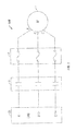
- FIGURE 1 shows a motor branch circuit assembly 100.
- Motor branch circuit assembly 100 includes a motor, line voltage phase unit 59 with phases A, B, and C, a motor contactor 3, and an overload relay 4.
- motor contactor 3 is replaced by either a Delayed Pole Contactor (DPC) or three independent Single Pole Switches (SPS).
- DPC Delayed Pole Contactor
- SPS Single Pole Switches
- FIGURE 2 shows an assembly 200 which is an external view of one embodiment of a three-pole DPC.
- Assembly 200 includes an enclosure 5, combined terminations and fixed contacts 6, a moving contact carrier molding 7, and attachment points 8 where screws fasten wires into assembly 200.
- FIGURE 3 illustrates a cross-section along line A-A assembly 200.
- assembly 200 Within assembly 200 lies a moving contact 9 a spring 10 that provides contact pressure on closing.
- An iron magnet frame 11 supports a magnet face 12 that mates with an armature 13.
- a coil 14 generates a magnetic flux and a spring 15 urges an actuating assembly away from magnet face 12 when the coil 14 is de-energized.
- Moving contact carrier molding 7 is physically attached to armature 13 such that they move together. Together, components 7, 11, 12, 13, 14, and 15 comprise the actuating assembly.
- FIGURE 4 is a cross-section along line B-B of assembly 200 showing moving contact carrier molding 7 with two identical outside poles 16 and 17 of the DPC and a center pole 18 that is physically offset by distance x so as to close at later time.
- a spring 19 is used to establish a contact closing pressure.
- Leaf springs 20 in poles 16 and 17 are used to establish initial contact pressure on closing. Though leaf springs 20 offer improved performance, it is equally suitable to eliminate them in a different embodiment and use only springs to establish initial contact pressure or use other compressible materials or manufactured items in their place. They may also be left out of poles designed to travel farther distances than the other poles.
- FIGUREs 5 and 6 show operation of center pole 18.
- center pole 18 in an open position has a contact gap g that is approximately equal to the sum of distance x in FIGURE 4 and contact gap h in FIGURE 6 .
- center pole 18 has a smaller contact gap h. This position is obtained by advancing the actuating assembly the distance x towards magnet face 12.
- FIGUREs 7 and 8 show operation of outside pole 16 or 17.
- outside pole 16 or 17 is in the open position a distance f from contact 6 with leaf spring 20 not compressed.
- Leaf spring 20 has a depth of distance y.
- FIGURE 8 outside pole 16 or 17 is in the closed position with leaf spring 20 compressed. This position is obtained by advancing the actuating assembly the distance f + y towards magnet face 12.
- FIGUREs 9 and 10 show the closing and opening timing sequences respectively of the DPC.
- outside poles 16 and 17 close at peak line voltage and center pole 18 closes 90 electrical degrees later
- center pole 18 opens at zero line current and outside poles 16 and 17 open 90 electrical degrees later.
- FIGURE 11 shows an assembly 400 incorporating Single Pole Switches (SPS).
- Assembly 400 includes an enclosure 20, combined terminations and fixed contacts 6, an extension of a moving contact carrier molding 21, and attachment points 8 where screws fasten the line and motor cables.
- SPS Single Pole Switches
- FIGURE 12 shows a cross-section along line AA-AA of assembly 400.
- Assembly 400 includes moving contact 9 and spring 10 that provides contact pressure on closing.
- Iron magnet frame 11 supports magnet face 12 that mates with armature 13.
- Coil 14 energizes iron magnet frame 11 and spring 15 is used to open magnet face 12 when coil 14 is de-energized.
- FIGURE 13 shows a cross-section along line BB-BB of assembly 400.
- Assembly 400 includes moving contact carrier molding 21 with spring 19 determining a pressure between moving contact 9 and fixed contact 6.
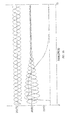
- FIGURE 14 shows a timing graph depicting an effect of the simultaneous connection of a three-phase supply to a delta connected motor.
- the curves depict a start for an unloaded delta motor with simultaneous closure of contactor poles.
- the bottom trace shows the severe torque pulsation and the middle curves show the very unbalanced three-phase line current.
- the top traces show the supply voltages from the moment of connection.
- FIGURE 15 shows a timing graph depicting an effect of the two-step connection of a three-phase supply to the same delta connected motor. Torque pulsation is virtually eliminated and the motor supply currents are balanced with significantly lower peak currents.
- the top voltage plots show the two-step connection timing sequence.
- FIGURE 16 illustrates an example set of connections for a motor in a wye-configuration.
- the contactor poles 1, 2, and 3 may be placed at either end of the windings.
- the DC transient flux ⁇ DC is on the other hand fixed in orientation 90° ahead of the direction of the initial supply vector u s ( t ) at the moment of switch-on and only gradually decays away.
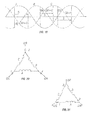
- FIGURE 17 shows a space vector expressing the relations in equations (3), (5), & (6).
- the steady state flux ⁇ ss ( t ) has constant amplitude and rotates about the fixed center determined by the transient ⁇ DC which only decays away slowly.
- ⁇ ss ( t ) rotates, the presence of the DC flux ⁇ DC causes the amplitude of the resultant flux ⁇ ( t ) to oscillate strongly.
- the effect is strong torque pulsations and unbalanced currents until the DC transient decays away.
- the DC transient may be greatly reduced or eliminated if the supply connection process is performed in two steps. While the embodiments for different motor combinations below describe the use of specific supply phases, any combination of supply phases that maintain the same timing and voltage aspects for the two-step connection described below are equally suitable. Indeed, the two-step connection described relates to operations that result in additional current flow into the motor. It is equally suitable to connect one phase of the motor at any time prior to these steps as long as it does not result in current flow into the motor. In such a case, current would only flow at the time a second phase of the motor was connected to the supply and would be equivalent to both phases being connected concurrently.
- FIGURE 18 shows a vector diagram for a two-step connection of contactor poles.
- the current flow through the motor windings builds up flux ⁇ 0 in the direction shown in Fig 18 .
- u SA , u SB , u SC are the voltages across the three windings.
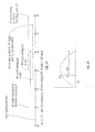
- FIGURE 19 shows the phase voltage waveforms showing three of the six possible connection timings for two-step closing of a wye-configured motor.
- the vertical lines denote the times when at least one phase of the supply is expected to be connected such that current flow into the motor windings is increased.
- the delay represented by ⁇ represents the period between the first connections resulting in current flow in the motor and the second connections resulting in all phases of the supply being connected the motor.
- FIGURE 20 illustrates a delta-configured motor with contactor poles connected outside the motor windings.
- the connection is done as for wye-configured motors by connecting two phases at their line amplitude peak by closing two poles as shown in FIGURE 20 . The remaining phase is then connected 90 degrees later by closing pole 3.
- phases A and C are the two phases initially closed, followed by phase B. The flux build up is now calculated.
- FIGURE 21 shows a delta-configured motor with contactor poles inside the motor windings. If the contactor poles for delta operation are placed within the delta (as is normal for wye-delta starting), the current flow in at least one winding can be achieved by connecting one phase of the motor to the supply as shown in FIGURE 21 . In FIGURE 21 , current flows in winding A when pole 1 connects the switched side of winding A to the phase C supply.
- Single Pole Switches have a DC operated electromagnet with electronic coil control operating a single set of fixed and moving contacts in an individual enclosure per FIGUREs 11 and 12 .
- Armature 13 in FIGURE 12 is acted upon by a magnetic field produced by the electromagnet coil 14 to control the connection and disconnection of contacts 6 and 9.
- They are used to connect individual phases of the supply to the motor as described in the three motor connection configurations described earlier. Because they allow for the independent control over the connection of each phase of the supply to a motor, they are well suited for use with a two-step closure process.
- the three contactor poles 1, 2, and 3 must be closed in the correct sequence at the desired points on the supply waveforms.
- two poles must connect the motor to the supply such that current first begins to flow in at least one motor winding at the peak voltage amplitude (approximately 90 degrees after the line-to-line zero-crossing of the two phases being connected). This can be accomplished by concurrently connecting both poles at this point on the supply waveform or by closing one pole at an earlier time and the other at this point on the supply waveform. Both approaches are equally suitable, though the latter may prove easier to implement.
- the remaining pole should be closed approximately 90 degrees later on the supply waveform.
- the three contactor poles 1, 2, and 3 must be closed in the correct sequence at the desired points on the supply waveforms.
- one pole must connect the motor to the supply such that current first begins to flow in one motor winding at a point 30 degrees prior to the peak voltage amplitude (approximately 60 degrees after the line-to-line zero-crossing of the two phases being connected).
- the remaining two poles should be closed approximately 120 degrees later on the supply waveform.
- This contact closure time represents the time from energizing the SPS magnetic coil until the contacts allow current to flow from the supply to the motor. This information can typically be gained by characterizing the design after it is in production.
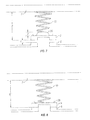
- t CE t ZC + d offset ⁇ X t Degree - t CC
- t CE the time at which the coil is to be energized
- t ZC the time of the zero-cross the estimated time is to be based on
- d Offset is the offset in degrees of the supply waveform from t ZC that the connection of the supply to the motor is desired
- t Degree is the time period equal to one degree of the supply waveform
- t CC is the period from when the SPS coil is energized to when the contacts allow current to flow from the supply to the motor.
- Delayed Pole Contactor An alternative to Single Pole Switches in implementing the two-step connection process is a Delayed Pole Contactor.
- This design is a three-pole contactor with the contacts arranged to close asynchronously at the preferred angles for the two-step connection process.
- the center pole is magnetically arranged to close later than the outer poles.
- the moving contact carrier has contact springs operating on contacts assembled in pole windows.
- the center contact is offset from the contacts of the two outer poles by having the center window smaller by the amount x.
- Using identical contacts and modifying the molded contact carrier gives the desired early closure of the outer poles.
- the contactor electromagnet is controlled so as to stall in this interim step one position.
- the contact gap h in the center pole is of sufficient dielectric strength to avoid conduction for approximately a quarter of the mains cycle following the contact closure of the outer two poles.
- This gap h is typically 0.5 mm to 1 mm depending on size of contactor.
- the power into the contactor-operating coil is controlled, such that in conjunction with the center contact physical offset and other contactor dynamics, so as to close the outer poles to this stalled position for a period equal to 90 electrical degrees of the supply frequency.
- the power into the contactor operating coil is then adjusted such that the contact springs in all poles are compressed past distance d, positioning the DPC in its final closed position.
- the power into the contactor-operating coil is reduced to a level sufficient to keep the contactor in the closed position.
- FIGURE 24 shows a motor circuit using a three-pole Delayed Pole Contactor (DPC) while FIGURE 25 shows a motor circuit using Single Pole Switches (SPS).
- a switch 53 is coupled to a controller 50.
- Controller 50 regulates power to the respective actuator assembly of the respective contactor in order to engage and disengage the contacts in accordance with the two-step connection.
- Controller 50 operates in association with a voltage zero-crossing monitor in regulating the power being applied.
Landscapes
- Engineering & Computer Science (AREA)
- Power Engineering (AREA)
- Physics & Mathematics (AREA)
- Electromagnetism (AREA)
- Motor And Converter Starters (AREA)
- Control Of Stepping Motors (AREA)
- Control Of Multiple Motors (AREA)
- Control Of Ac Motors In General (AREA)
Applications Claiming Priority (1)
| Application Number | Priority Date | Filing Date | Title |
|---|---|---|---|
| US13/815,863 US9590536B2 (en) | 2013-03-15 | 2013-03-15 | Two-step connection of electric motors by means of electromagnetic switches |
Publications (3)
| Publication Number | Publication Date |
|---|---|
| EP2787518A2 true EP2787518A2 (fr) | 2014-10-08 |
| EP2787518A3 EP2787518A3 (fr) | 2016-01-06 |
| EP2787518B1 EP2787518B1 (fr) | 2018-07-11 |
Family
ID=50391004
Family Applications (1)
| Application Number | Title | Priority Date | Filing Date |
|---|---|---|---|
| EP14160339.9A Active EP2787518B1 (fr) | 2013-03-15 | 2014-03-17 | Connexion en deux étapes de moteurs électriques au moyen de commutateurs électromagnétiques |
Country Status (3)
| Country | Link |
|---|---|
| US (1) | US9590536B2 (fr) |
| EP (1) | EP2787518B1 (fr) |
| CN (2) | CN109546894B (fr) |
Cited By (5)
| Publication number | Priority date | Publication date | Assignee | Title |
|---|---|---|---|---|
| EP3018677A1 (fr) * | 2014-11-06 | 2016-05-11 | Rockwell Automation Technologies, Inc. | Pôle unique, système de commutation de trajet de courant unique et procédé |
| EP3439164A1 (fr) * | 2017-08-04 | 2019-02-06 | Rockwell Automation Technologies, Inc. | Dispositif de commutation de puissance avec programmation améliorée |
| EP3439166A1 (fr) * | 2017-08-04 | 2019-02-06 | Rockwell Automation Technologies, Inc. | Contrôleur de moteur à circuit imprimé à commutation de puissance |
| CN109391174A (zh) * | 2017-08-04 | 2019-02-26 | 罗克韦尔自动化技术公司 | 基于pcb的电机起动器 |
| EP3787001A1 (fr) * | 2019-08-29 | 2021-03-03 | Rockwell Automation Technologies, Inc. | Démarreur de moteur compact |
Families Citing this family (17)
| Publication number | Priority date | Publication date | Assignee | Title |
|---|---|---|---|---|
| US9748873B2 (en) | 2014-11-06 | 2017-08-29 | Rockwell Automation Technologies, Inc. | 5-pole based wye-delta motor starting system and method |
| US10074497B2 (en) | 2014-11-06 | 2018-09-11 | Rockwell Automation Technologies, Inc. | Operator coil parameter based electromagnetic switching |
| US9772381B2 (en) | 2014-11-06 | 2017-09-26 | Rockwell Automation Technologies, Inc. | Synchronized reapplication of power for driving an electric motor |
| US10141143B2 (en) | 2014-11-06 | 2018-11-27 | Rockwell Automation Technologies, Inc. | Wear-balanced electromagnetic motor control switching |
| US9806642B2 (en) | 2014-11-06 | 2017-10-31 | Rockwell Automation Technologies, Inc. | Modular multiple single-pole electromagnetic switching system and method |
| US9806641B2 (en) | 2014-11-06 | 2017-10-31 | Rockwell Automation Technologies, Inc. | Detection of electric motor short circuits |
| US9722513B2 (en) | 2014-11-06 | 2017-08-01 | Rockwell Automation Technologies, Inc. | Torque-based stepwise motor starting |
| CN104319186B (zh) * | 2014-11-17 | 2017-11-17 | 蒋胜泉 | 可控制多负载的时序继电器 |
| DE112015005461B4 (de) * | 2014-12-05 | 2023-06-15 | Omron Corporation | Elektromagnetisches Relais |
| JP2016110843A (ja) | 2014-12-05 | 2016-06-20 | オムロン株式会社 | 電磁継電器 |
| JP6414453B2 (ja) | 2014-12-05 | 2018-10-31 | オムロン株式会社 | 電磁継電器 |
| JP6388564B2 (ja) * | 2015-07-09 | 2018-09-12 | 三菱電機株式会社 | 電動機応用製品 |
| JP6176364B1 (ja) * | 2016-06-14 | 2017-08-09 | 富士電機機器制御株式会社 | 接点装置及びこれを使用した電磁接触器 |
| US10134551B2 (en) * | 2016-09-21 | 2018-11-20 | Astronics Advanced Electronic Systems Corp. | Galvanically isolated hybrid contactor |
| JP6332480B1 (ja) * | 2017-01-11 | 2018-05-30 | 富士電機機器制御株式会社 | 電磁接触器 |
| DE102017220503B3 (de) * | 2017-11-16 | 2019-01-17 | Te Connectivity Germany Gmbh | Doppelt unterbrechender Schalter |
| JP7304786B2 (ja) * | 2019-10-04 | 2023-07-07 | 日立Astemo株式会社 | 回転機駆動システム及び車両 |
Family Cites Families (16)
| Publication number | Priority date | Publication date | Assignee | Title |
|---|---|---|---|---|
| DE951020C (de) | 1951-11-25 | 1956-10-18 | Siemens Ag | Drehstromschuetz fuer synchrones Ausschalten, dessen Kontakte zwecks Vermeidung von Schaltfeuer kurz vor dem Nulldurchgang des Stromes geoeffnet werden |
| DE3143430C2 (de) | 1981-11-02 | 1984-05-24 | Siemens AG, 1000 Berlin und 8000 München | Drehstromschaltgerät für einen an drei Phasen anzuschließenden Verbraucher |
| JPS63184225A (ja) | 1987-01-27 | 1988-07-29 | 富士電機株式会社 | 電磁接触器 |
| US5430599A (en) * | 1993-03-18 | 1995-07-04 | Hydro-Quebec | System for opening/closing circuit breakers |
| KR20000073458A (ko) | 1999-05-11 | 2000-12-05 | 권수영 | 스타-델타 결선용 전자개폐기 |
| DE10008299A1 (de) | 2000-02-23 | 2001-09-27 | Daimler Chrysler Ag | Verfahren zum Betreiben eines elektrischen Generator/Motor-Systems |
| US6956728B2 (en) * | 2003-02-28 | 2005-10-18 | Eaton Corporation | Method and apparatus to control modular asynchronous contactors |
| US7196434B2 (en) | 2003-03-21 | 2007-03-27 | Eaton Corporation | Modular contactor assembly having independently controllable contractors |
| US7224557B2 (en) * | 2003-06-28 | 2007-05-29 | Eaton Corporation | Method and system of controlling asynchronous contactors for a multi-phase electric load |
| US7317264B2 (en) * | 2003-11-25 | 2008-01-08 | Eaton Corporation | Method and apparatus to independently control contactors in a multiple contactor configuration |
| GB0421443D0 (en) | 2004-09-27 | 2004-10-27 | Unsworth Peter | Point on wave (pow) control for motor starting and switching |
| US7576957B2 (en) * | 2006-05-01 | 2009-08-18 | Eaton Corporation | Circuit interrupter including point-on-wave controller and voltage sensors |
| EP1953780B1 (fr) * | 2007-02-02 | 2011-01-26 | Abb Research Ltd. | Dispositif de commutation électrique, son utilisation et procédé de commutation |
| CN201365218Y (zh) | 2009-02-25 | 2009-12-16 | 河海大学 | 一种三相交流电机相序控制器 |
| WO2011116488A1 (fr) * | 2010-03-22 | 2011-09-29 | Siemens Aktiengesellschaft | Procédé et appareil permettant de supprimer le courant d'appel d'un transformateur |
| CN102368672B (zh) | 2011-07-19 | 2014-05-28 | 株洲变流技术国家工程研究中心有限公司 | 一种电动机软起动仿真装置及其方法 |
-
2013
- 2013-03-15 US US13/815,863 patent/US9590536B2/en active Active
-
2014
- 2014-03-17 CN CN201811208539.0A patent/CN109546894B/zh active Active
- 2014-03-17 EP EP14160339.9A patent/EP2787518B1/fr active Active
- 2014-03-17 CN CN201410099213.4A patent/CN104052338B/zh active Active
Non-Patent Citations (1)
| Title |
|---|
| None |
Cited By (11)
| Publication number | Priority date | Publication date | Assignee | Title |
|---|---|---|---|---|
| EP3018677A1 (fr) * | 2014-11-06 | 2016-05-11 | Rockwell Automation Technologies, Inc. | Pôle unique, système de commutation de trajet de courant unique et procédé |
| EP3439164A1 (fr) * | 2017-08-04 | 2019-02-06 | Rockwell Automation Technologies, Inc. | Dispositif de commutation de puissance avec programmation améliorée |
| EP3439166A1 (fr) * | 2017-08-04 | 2019-02-06 | Rockwell Automation Technologies, Inc. | Contrôleur de moteur à circuit imprimé à commutation de puissance |
| CN109391173A (zh) * | 2017-08-04 | 2019-02-26 | 罗克韦尔自动化技术公司 | 利用pow切换的pcb电机控制器 |
| CN109391174A (zh) * | 2017-08-04 | 2019-02-26 | 罗克韦尔自动化技术公司 | 基于pcb的电机起动器 |
| EP3439165A3 (fr) * | 2017-08-04 | 2019-05-01 | Rockwell Automation Technologies, Inc. | Démarreur de moteur à pcb |
| US10396689B2 (en) | 2017-08-04 | 2019-08-27 | Rockwell Automation Technologies, Inc. | PCB-based motor starter |
| US10396688B2 (en) | 2017-08-04 | 2019-08-27 | Rockwell Automation Technologies, Inc. | PCB motor controller with POW switching |
| US10395857B2 (en) | 2017-08-04 | 2019-08-27 | Rockwell Automation Technologies, Inc. | POW switching device with enhanced programming |
| EP3787001A1 (fr) * | 2019-08-29 | 2021-03-03 | Rockwell Automation Technologies, Inc. | Démarreur de moteur compact |
| US11496079B2 (en) | 2019-08-29 | 2022-11-08 | Rockwell Automation Technologies, Inc. | Compact motor starter |
Also Published As
| Publication number | Publication date |
|---|---|
| US20140265995A1 (en) | 2014-09-18 |
| EP2787518B1 (fr) | 2018-07-11 |
| EP2787518A3 (fr) | 2016-01-06 |
| CN104052338A (zh) | 2014-09-17 |
| CN104052338B (zh) | 2018-11-16 |
| CN109546894A (zh) | 2019-03-29 |
| CN109546894B (zh) | 2022-04-05 |
| US9590536B2 (en) | 2017-03-07 |
Similar Documents
| Publication | Publication Date | Title |
|---|---|---|
| EP2787518B1 (fr) | Connexion en deux étapes de moteurs électriques au moyen de commutateurs électromagnétiques | |
| US10347440B2 (en) | Multipole electromechanical switching device | |
| US7224557B2 (en) | Method and system of controlling asynchronous contactors for a multi-phase electric load | |
| EP1820259B1 (fr) | Demarrage et commutation de moteur | |
| US10101393B2 (en) | Temperature-based electromagnetic switching | |
| US10361051B2 (en) | Single pole, single current path switching system and method | |
| US10141143B2 (en) | Wear-balanced electromagnetic motor control switching | |
| US9806641B2 (en) | Detection of electric motor short circuits | |
| US20160134210A1 (en) | Modular multiple single-pole electromagnetic switching system and method | |
| US9722513B2 (en) | Torque-based stepwise motor starting | |
| EP2750285B1 (fr) | Procédé de commutation et dispositif de commande associé | |
| Zhou et al. | Asynchronous modular contactor for intelligent motor control applications |
Legal Events
| Date | Code | Title | Description |
|---|---|---|---|
| PUAI | Public reference made under article 153(3) epc to a published international application that has entered the european phase |
Free format text: ORIGINAL CODE: 0009012 |
|
| 17P | Request for examination filed |
Effective date: 20140317 |
|
| AK | Designated contracting states |
Kind code of ref document: A2 Designated state(s): AL AT BE BG CH CY CZ DE DK EE ES FI FR GB GR HR HU IE IS IT LI LT LU LV MC MK MT NL NO PL PT RO RS SE SI SK SM TR |
|
| AX | Request for extension of the european patent |
Extension state: BA ME |
|
| PUAL | Search report despatched |
Free format text: ORIGINAL CODE: 0009013 |
|
| AK | Designated contracting states |
Kind code of ref document: A3 Designated state(s): AL AT BE BG CH CY CZ DE DK EE ES FI FR GB GR HR HU IE IS IT LI LT LU LV MC MK MT NL NO PL PT RO RS SE SI SK SM TR |
|
| AX | Request for extension of the european patent |
Extension state: BA ME |
|
| RIC1 | Information provided on ipc code assigned before grant |
Ipc: H01H 9/56 20060101AFI20151202BHEP Ipc: H02P 1/32 20060101ALI20151202BHEP Ipc: H01H 50/54 20060101ALI20151202BHEP Ipc: H01P 1/26 20060101ALI20151202BHEP Ipc: H01H 1/20 20060101ALN20151202BHEP |
|
| RIN1 | Information on inventor provided before grant (corrected) |
Inventor name: JAMES J. KINSELLA Inventor name: PETER UNSWORTH Inventor name: CHRISTOPH J. WIELOCH |
|
| R17P | Request for examination filed (corrected) |
Effective date: 20160705 |
|
| RBV | Designated contracting states (corrected) |
Designated state(s): AL AT BE BG CH CY CZ DE DK EE ES FI FR GB GR HR HU IE IS IT LI LT LU LV MC MK MT NL NO PL PT RO RS SE SI SK SM TR |
|
| STAA | Information on the status of an ep patent application or granted ep patent |
Free format text: STATUS: EXAMINATION IS IN PROGRESS |
|
| 17Q | First examination report despatched |
Effective date: 20170127 |
|
| GRAP | Despatch of communication of intention to grant a patent |
Free format text: ORIGINAL CODE: EPIDOSNIGR1 |
|
| STAA | Information on the status of an ep patent application or granted ep patent |
Free format text: STATUS: GRANT OF PATENT IS INTENDED |
|
| RIC1 | Information provided on ipc code assigned before grant |
Ipc: H01P 1/26 20060101ALI20180131BHEP Ipc: H02P 1/32 20060101ALI20180131BHEP Ipc: H01H 9/56 20060101AFI20180131BHEP Ipc: H01H 50/54 20060101ALI20180131BHEP Ipc: H01H 1/20 20060101ALN20180131BHEP |
|
| INTG | Intention to grant announced |
Effective date: 20180302 |
|
| RIN1 | Information on inventor provided before grant (corrected) |
Inventor name: CHRISTOPHER J. WIELOCH Inventor name: JAMES J. KINSELLA Inventor name: PETER UNSWORTH |
|
| GRAA | (expected) grant |
Free format text: ORIGINAL CODE: 0009210 |
|
| STAA | Information on the status of an ep patent application or granted ep patent |
Free format text: STATUS: THE PATENT HAS BEEN GRANTED |
|
| AK | Designated contracting states |
Kind code of ref document: B1 Designated state(s): AL AT BE BG CH CY CZ DE DK EE ES FI FR GB GR HR HU IE IS IT LI LT LU LV MC MK MT NL NO PL PT RO RS SE SI SK SM TR |
|
| REG | Reference to a national code |
Ref country code: GB Ref legal event code: FG4D |
|
| REG | Reference to a national code |
Ref country code: CH Ref legal event code: EP |
|
| REG | Reference to a national code |
Ref country code: AT Ref legal event code: REF Ref document number: 1017781 Country of ref document: AT Kind code of ref document: T Effective date: 20180715 |
|
| GRAS | Grant fee paid |
Free format text: ORIGINAL CODE: EPIDOSNIGR3 |
|
| REG | Reference to a national code |
Ref country code: DE Ref legal event code: R096 Ref document number: 602014028157 Country of ref document: DE |
|
| REG | Reference to a national code |
Ref country code: IE Ref legal event code: FG4D |
|
| REG | Reference to a national code |
Ref country code: NL Ref legal event code: MP Effective date: 20180711 |
|
| REG | Reference to a national code |
Ref country code: LT Ref legal event code: MG4D |
|
| REG | Reference to a national code |
Ref country code: AT Ref legal event code: MK05 Ref document number: 1017781 Country of ref document: AT Kind code of ref document: T Effective date: 20180711 |
|
| PG25 | Lapsed in a contracting state [announced via postgrant information from national office to epo] |
Ref country code: NL Free format text: LAPSE BECAUSE OF FAILURE TO SUBMIT A TRANSLATION OF THE DESCRIPTION OR TO PAY THE FEE WITHIN THE PRESCRIBED TIME-LIMIT Effective date: 20180711 |
|
| PG25 | Lapsed in a contracting state [announced via postgrant information from national office to epo] |
Ref country code: PL Free format text: LAPSE BECAUSE OF FAILURE TO SUBMIT A TRANSLATION OF THE DESCRIPTION OR TO PAY THE FEE WITHIN THE PRESCRIBED TIME-LIMIT Effective date: 20180711 Ref country code: LT Free format text: LAPSE BECAUSE OF FAILURE TO SUBMIT A TRANSLATION OF THE DESCRIPTION OR TO PAY THE FEE WITHIN THE PRESCRIBED TIME-LIMIT Effective date: 20180711 Ref country code: GR Free format text: LAPSE BECAUSE OF FAILURE TO SUBMIT A TRANSLATION OF THE DESCRIPTION OR TO PAY THE FEE WITHIN THE PRESCRIBED TIME-LIMIT Effective date: 20181012 Ref country code: NO Free format text: LAPSE BECAUSE OF FAILURE TO SUBMIT A TRANSLATION OF THE DESCRIPTION OR TO PAY THE FEE WITHIN THE PRESCRIBED TIME-LIMIT Effective date: 20181011 Ref country code: BG Free format text: LAPSE BECAUSE OF FAILURE TO SUBMIT A TRANSLATION OF THE DESCRIPTION OR TO PAY THE FEE WITHIN THE PRESCRIBED TIME-LIMIT Effective date: 20181011 Ref country code: SE Free format text: LAPSE BECAUSE OF FAILURE TO SUBMIT A TRANSLATION OF THE DESCRIPTION OR TO PAY THE FEE WITHIN THE PRESCRIBED TIME-LIMIT Effective date: 20180711 Ref country code: AT Free format text: LAPSE BECAUSE OF FAILURE TO SUBMIT A TRANSLATION OF THE DESCRIPTION OR TO PAY THE FEE WITHIN THE PRESCRIBED TIME-LIMIT Effective date: 20180711 Ref country code: RS Free format text: LAPSE BECAUSE OF FAILURE TO SUBMIT A TRANSLATION OF THE DESCRIPTION OR TO PAY THE FEE WITHIN THE PRESCRIBED TIME-LIMIT Effective date: 20180711 Ref country code: IS Free format text: LAPSE BECAUSE OF FAILURE TO SUBMIT A TRANSLATION OF THE DESCRIPTION OR TO PAY THE FEE WITHIN THE PRESCRIBED TIME-LIMIT Effective date: 20181111 Ref country code: FI Free format text: LAPSE BECAUSE OF FAILURE TO SUBMIT A TRANSLATION OF THE DESCRIPTION OR TO PAY THE FEE WITHIN THE PRESCRIBED TIME-LIMIT Effective date: 20180711 |
|
| PG25 | Lapsed in a contracting state [announced via postgrant information from national office to epo] |
Ref country code: ES Free format text: LAPSE BECAUSE OF FAILURE TO SUBMIT A TRANSLATION OF THE DESCRIPTION OR TO PAY THE FEE WITHIN THE PRESCRIBED TIME-LIMIT Effective date: 20180711 Ref country code: AL Free format text: LAPSE BECAUSE OF FAILURE TO SUBMIT A TRANSLATION OF THE DESCRIPTION OR TO PAY THE FEE WITHIN THE PRESCRIBED TIME-LIMIT Effective date: 20180711 Ref country code: HR Free format text: LAPSE BECAUSE OF FAILURE TO SUBMIT A TRANSLATION OF THE DESCRIPTION OR TO PAY THE FEE WITHIN THE PRESCRIBED TIME-LIMIT Effective date: 20180711 Ref country code: LV Free format text: LAPSE BECAUSE OF FAILURE TO SUBMIT A TRANSLATION OF THE DESCRIPTION OR TO PAY THE FEE WITHIN THE PRESCRIBED TIME-LIMIT Effective date: 20180711 |
|
| REG | Reference to a national code |
Ref country code: DE Ref legal event code: R097 Ref document number: 602014028157 Country of ref document: DE |
|
| PG25 | Lapsed in a contracting state [announced via postgrant information from national office to epo] |
Ref country code: IT Free format text: LAPSE BECAUSE OF FAILURE TO SUBMIT A TRANSLATION OF THE DESCRIPTION OR TO PAY THE FEE WITHIN THE PRESCRIBED TIME-LIMIT Effective date: 20180711 Ref country code: EE Free format text: LAPSE BECAUSE OF FAILURE TO SUBMIT A TRANSLATION OF THE DESCRIPTION OR TO PAY THE FEE WITHIN THE PRESCRIBED TIME-LIMIT Effective date: 20180711 Ref country code: RO Free format text: LAPSE BECAUSE OF FAILURE TO SUBMIT A TRANSLATION OF THE DESCRIPTION OR TO PAY THE FEE WITHIN THE PRESCRIBED TIME-LIMIT Effective date: 20180711 Ref country code: CZ Free format text: LAPSE BECAUSE OF FAILURE TO SUBMIT A TRANSLATION OF THE DESCRIPTION OR TO PAY THE FEE WITHIN THE PRESCRIBED TIME-LIMIT Effective date: 20180711 |
|
| PLBE | No opposition filed within time limit |
Free format text: ORIGINAL CODE: 0009261 |
|
| STAA | Information on the status of an ep patent application or granted ep patent |
Free format text: STATUS: NO OPPOSITION FILED WITHIN TIME LIMIT |
|
| PG25 | Lapsed in a contracting state [announced via postgrant information from national office to epo] |
Ref country code: DK Free format text: LAPSE BECAUSE OF FAILURE TO SUBMIT A TRANSLATION OF THE DESCRIPTION OR TO PAY THE FEE WITHIN THE PRESCRIBED TIME-LIMIT Effective date: 20180711 Ref country code: SK Free format text: LAPSE BECAUSE OF FAILURE TO SUBMIT A TRANSLATION OF THE DESCRIPTION OR TO PAY THE FEE WITHIN THE PRESCRIBED TIME-LIMIT Effective date: 20180711 Ref country code: SM Free format text: LAPSE BECAUSE OF FAILURE TO SUBMIT A TRANSLATION OF THE DESCRIPTION OR TO PAY THE FEE WITHIN THE PRESCRIBED TIME-LIMIT Effective date: 20180711 |
|
| 26N | No opposition filed |
Effective date: 20190412 |
|
| PG25 | Lapsed in a contracting state [announced via postgrant information from national office to epo] |
Ref country code: SI Free format text: LAPSE BECAUSE OF FAILURE TO SUBMIT A TRANSLATION OF THE DESCRIPTION OR TO PAY THE FEE WITHIN THE PRESCRIBED TIME-LIMIT Effective date: 20180711 |
|
| PG25 | Lapsed in a contracting state [announced via postgrant information from national office to epo] |
Ref country code: MC Free format text: LAPSE BECAUSE OF FAILURE TO SUBMIT A TRANSLATION OF THE DESCRIPTION OR TO PAY THE FEE WITHIN THE PRESCRIBED TIME-LIMIT Effective date: 20180711 |
|
| REG | Reference to a national code |
Ref country code: CH Ref legal event code: PL |
|
| PG25 | Lapsed in a contracting state [announced via postgrant information from national office to epo] |
Ref country code: LU Free format text: LAPSE BECAUSE OF NON-PAYMENT OF DUE FEES Effective date: 20190317 |
|
| REG | Reference to a national code |
Ref country code: BE Ref legal event code: MM Effective date: 20190331 |
|
| PG25 | Lapsed in a contracting state [announced via postgrant information from national office to epo] |
Ref country code: LI Free format text: LAPSE BECAUSE OF NON-PAYMENT OF DUE FEES Effective date: 20190331 Ref country code: IE Free format text: LAPSE BECAUSE OF NON-PAYMENT OF DUE FEES Effective date: 20190317 Ref country code: CH Free format text: LAPSE BECAUSE OF NON-PAYMENT OF DUE FEES Effective date: 20190331 |
|
| PG25 | Lapsed in a contracting state [announced via postgrant information from national office to epo] |
Ref country code: BE Free format text: LAPSE BECAUSE OF NON-PAYMENT OF DUE FEES Effective date: 20190331 |
|
| PG25 | Lapsed in a contracting state [announced via postgrant information from national office to epo] |
Ref country code: TR Free format text: LAPSE BECAUSE OF FAILURE TO SUBMIT A TRANSLATION OF THE DESCRIPTION OR TO PAY THE FEE WITHIN THE PRESCRIBED TIME-LIMIT Effective date: 20180711 |
|
| PG25 | Lapsed in a contracting state [announced via postgrant information from national office to epo] |
Ref country code: MT Free format text: LAPSE BECAUSE OF NON-PAYMENT OF DUE FEES Effective date: 20190317 Ref country code: PT Free format text: LAPSE BECAUSE OF FAILURE TO SUBMIT A TRANSLATION OF THE DESCRIPTION OR TO PAY THE FEE WITHIN THE PRESCRIBED TIME-LIMIT Effective date: 20181111 |
|
| PG25 | Lapsed in a contracting state [announced via postgrant information from national office to epo] |
Ref country code: CY Free format text: LAPSE BECAUSE OF FAILURE TO SUBMIT A TRANSLATION OF THE DESCRIPTION OR TO PAY THE FEE WITHIN THE PRESCRIBED TIME-LIMIT Effective date: 20180711 |
|
| PG25 | Lapsed in a contracting state [announced via postgrant information from national office to epo] |
Ref country code: HU Free format text: LAPSE BECAUSE OF FAILURE TO SUBMIT A TRANSLATION OF THE DESCRIPTION OR TO PAY THE FEE WITHIN THE PRESCRIBED TIME-LIMIT; INVALID AB INITIO Effective date: 20140317 |
|
| PG25 | Lapsed in a contracting state [announced via postgrant information from national office to epo] |
Ref country code: MK Free format text: LAPSE BECAUSE OF FAILURE TO SUBMIT A TRANSLATION OF THE DESCRIPTION OR TO PAY THE FEE WITHIN THE PRESCRIBED TIME-LIMIT Effective date: 20180711 |
|
| P01 | Opt-out of the competence of the unified patent court (upc) registered |
Effective date: 20230404 |
|
| PGFP | Annual fee paid to national office [announced via postgrant information from national office to epo] |
Ref country code: GB Payment date: 20260219 Year of fee payment: 13 |
|
| PGFP | Annual fee paid to national office [announced via postgrant information from national office to epo] |
Ref country code: DE Payment date: 20260219 Year of fee payment: 13 |
|
| PGFP | Annual fee paid to national office [announced via postgrant information from national office to epo] |
Ref country code: FR Payment date: 20260220 Year of fee payment: 13 |