US9590536B2 - Two-step connection of electric motors by means of electromagnetic switches - Google Patents
Two-step connection of electric motors by means of electromagnetic switches Download PDFInfo
- Publication number
- US9590536B2 US9590536B2 US13/815,863 US201313815863A US9590536B2 US 9590536 B2 US9590536 B2 US 9590536B2 US 201313815863 A US201313815863 A US 201313815863A US 9590536 B2 US9590536 B2 US 9590536B2
- Authority
- US
- United States
- Prior art keywords
- contacts
- motor
- direct current
- electromagnetically controlled
- phase
- Prior art date
- Legal status (The legal status is an assumption and is not a legal conclusion. Google has not performed a legal analysis and makes no representation as to the accuracy of the status listed.)
- Active, expires
Links
- 238000000034 method Methods 0.000 claims abstract description 34
- 230000008569 process Effects 0.000 claims abstract description 17
- 238000004804 winding Methods 0.000 claims description 42
- 238000012544 monitoring process Methods 0.000 claims description 8
- 230000007704 transition Effects 0.000 claims 1
- 230000010355 oscillation Effects 0.000 abstract description 2
- 230000004907 flux Effects 0.000 description 27
- 230000001052 transient effect Effects 0.000 description 23
- 230000010349 pulsation Effects 0.000 description 13
- 230000003111 delayed effect Effects 0.000 description 8
- XEEYBQQBJWHFJM-UHFFFAOYSA-N Iron Chemical compound [Fe] XEEYBQQBJWHFJM-UHFFFAOYSA-N 0.000 description 6
- 238000010586 diagram Methods 0.000 description 6
- 230000000694 effects Effects 0.000 description 6
- 239000007858 starting material Substances 0.000 description 6
- 238000000465 moulding Methods 0.000 description 5
- 238000013459 approach Methods 0.000 description 3
- 229910052742 iron Inorganic materials 0.000 description 3
- 230000004075 alteration Effects 0.000 description 2
- 230000001276 controlling effect Effects 0.000 description 2
- 238000013461 design Methods 0.000 description 2
- 230000006698 induction Effects 0.000 description 2
- 230000010354 integration Effects 0.000 description 2
- 238000012986 modification Methods 0.000 description 2
- 230000004048 modification Effects 0.000 description 2
- 238000006467 substitution reaction Methods 0.000 description 2
- 230000015556 catabolic process Effects 0.000 description 1
- 230000008859 change Effects 0.000 description 1
- 238000006243 chemical reaction Methods 0.000 description 1
- 238000010276 construction Methods 0.000 description 1
- 230000008878 coupling Effects 0.000 description 1
- 238000010168 coupling process Methods 0.000 description 1
- 238000005859 coupling reaction Methods 0.000 description 1
- 230000001066 destructive effect Effects 0.000 description 1
- 230000005284 excitation Effects 0.000 description 1
- 230000005415 magnetization Effects 0.000 description 1
- 238000004519 manufacturing process Methods 0.000 description 1
- 239000000463 material Substances 0.000 description 1
- 230000007246 mechanism Effects 0.000 description 1
- 230000003534 oscillatory effect Effects 0.000 description 1
- 238000000819 phase cycle Methods 0.000 description 1
- 230000001105 regulatory effect Effects 0.000 description 1
- 230000001360 synchronised effect Effects 0.000 description 1
Images


Classifications
-
- H—ELECTRICITY
- H02—GENERATION; CONVERSION OR DISTRIBUTION OF ELECTRIC POWER
- H02P—CONTROL OR REGULATION OF ELECTRIC MOTORS, ELECTRIC GENERATORS OR DYNAMO-ELECTRIC CONVERTERS; CONTROLLING TRANSFORMERS, REACTORS OR CHOKE COILS
- H02P1/00—Arrangements for starting electric motors or dynamo-electric converters
- H02P1/16—Arrangements for starting electric motors or dynamo-electric converters for starting dynamo-electric motors or dynamo-electric converters
- H02P1/26—Arrangements for starting electric motors or dynamo-electric converters for starting dynamo-electric motors or dynamo-electric converters for starting an individual polyphase induction motor
-
- H—ELECTRICITY
- H01—ELECTRIC ELEMENTS
- H01H—ELECTRIC SWITCHES; RELAYS; SELECTORS; EMERGENCY PROTECTIVE DEVICES
- H01H1/00—Contacts
- H01H1/12—Contacts characterised by the manner in which co-operating contacts engage
- H01H1/14—Contacts characterised by the manner in which co-operating contacts engage by abutting
- H01H1/20—Bridging contacts
- H01H1/2016—Bridging contacts in which the two contact pairs commutate at substantially different moments
-
- H—ELECTRICITY
- H01—ELECTRIC ELEMENTS
- H01H—ELECTRIC SWITCHES; RELAYS; SELECTORS; EMERGENCY PROTECTIVE DEVICES
- H01H50/00—Details of electromagnetic relays
- H01H50/54—Contact arrangements
-
- H—ELECTRICITY
- H02—GENERATION; CONVERSION OR DISTRIBUTION OF ELECTRIC POWER
- H02P—CONTROL OR REGULATION OF ELECTRIC MOTORS, ELECTRIC GENERATORS OR DYNAMO-ELECTRIC CONVERTERS; CONTROLLING TRANSFORMERS, REACTORS OR CHOKE COILS
- H02P1/00—Arrangements for starting electric motors or dynamo-electric converters
- H02P1/16—Arrangements for starting electric motors or dynamo-electric converters for starting dynamo-electric motors or dynamo-electric converters
- H02P1/26—Arrangements for starting electric motors or dynamo-electric converters for starting dynamo-electric motors or dynamo-electric converters for starting an individual polyphase induction motor
- H02P1/32—Arrangements for starting electric motors or dynamo-electric converters for starting dynamo-electric motors or dynamo-electric converters for starting an individual polyphase induction motor by star/delta switching
Definitions
- the present disclosure relates in general to the control, protection, and starting of three-phase electric motors and driven equipment and more particularly to a two-step connection of electric motors by means of electromagnetic switches.
- Embodiments contain electromagnetic switches providing a two-step connection process resulting in some windings of the motor experiencing current flow before the remainder of windings experience current flow. Two such possible embodiments of providing two-step switching are described.
- One embodiment uses Single Pole Switches (SPS).
- Another embodiment uses a Delayed Pole Contactor (DPC) comprised of three poles with one pole designed to close at an offset in time relative to the closing of the other two poles.
- SPS Single Pole Switches
- DPC Delayed Pole Contactor
- both embodiments use DC electromagnets controlled by electronic means, though other means capable of controlling the operation of the switches are also satisfactory.
- FIG. 1 illustrates a motor branch circuit assembly
- FIG. 2 illustrates an assembly which is an external view of an embodiment using a three-pole Delayed Pole Contactor (DPC);
- DPC Delayed Pole Contactor
- FIG. 3 illustrates a cross-section of the assembly of FIG. 2 ;
- FIG. 4 illustrates another cross-section of the assembly of FIG. 2 ;
- FIGS. 5 and 6 illustrate an operation of a center pole of the assembly
- FIGS. 7 and 8 illustrate operation of an outside pole of the assembly
- FIGS. 9 and 10 illustrate closing and opening timing sequences for the assembly
- FIG. 11 illustrates an assembly which is an external view of an embodiment using Single Pole Switches (SPS);
- SPS Single Pole Switches
- FIG. 12 illustrates a cross-section of the assembly of FIG. 11 ;
- FIG. 13 illustrates another cross-section of the assembly of FIG. 11 ;
- FIG. 14 illustrates a graph depicting an effect of a simultaneous connection of a three-phase supply to a delta connected motor
- FIG. 15 illustrates a timing graph depicting an effect of a two step connection of a three-phase supply to a delta connected motor
- FIG. 16 illustrates an example set of connections for a motor in a wye configuration
- FIG. 17 illustrates a vector diagram for simultaneous closing of all contactor poles
- FIG. 18 illustrates a vector diagram for two-step connection of contactor poles
- FIG. 19 illustrates the phase voltage waveforms of three of six possible connection timings for a two-step closing of a wye-configured motor
- FIG. 20 illustrates a delta-configured motor with contactor poles connected outside the motor windings
- FIG. 21 illustrates a delta-configured motor with contactor poles inside the motor windings
- FIG. 22 illustrates a timing diagram for the first step closing at 60 electrical degrees for a delta-configured motor with contactor poles inside the motor windings
- FIG. 23 illustrates a timing diagram for closure of individual contactor poles for two-step starting of a wye-configured motor
- FIG. 24 illustrates a motor circuit using a three-pole Delayed Pole Contactor (DPC);
- DPC Delayed Pole Contactor
- FIG. 25 illustrates a motor circuit using Single Pole Switches (SPS).
- SPS Single Pole Switches
- the motor When an electromagnetic contactor is used to start an induction motor from rest, the motor typically draws a starting current from the supply that is between six and ten times the motor full load current (FLC), depending on the size and construction of the motor. As the motor approaches full speed, the current falls to a lesser value commensurate with the load on the motor.
- FLC motor full load current
- the effect of the DC current is to cause the severe torque pulsation that accompanies motor starting. This happens because, instead of the uniformly rotating magnetic field that the steady state AC currents would produce, the DC transient introduces an additional non-rotating, decaying DC field component. This adds to the AC field when they are aligned but subtracts from the AC field as the stator field moves out of alignment with the DC field component. Instead of keeping a steady (rotating) value, the motor flux therefore oscillates between (AC flux+DC flux) and (AC flux ⁇ DC flux). This causes a severe oscillation in motor torque at supply frequency that only subsides as the DC flux decays away. This may last several seconds in larger motors.
- a two-step connection process is able to eliminate surges due to the slow decaying excitation DC transient current and associated torque pulsation.
- two phases of the motor are first connected to the supply terminals to build up current in two of the motor windings so that, at the moment when the remaining phase is connected, all three currents are exactly equal to their steady state AC values corresponding to the point all phases are finally connected to the supply waveforms. If the currents are at the steady state value immediately before and after connection of the third phase, no additional DC transient current is generated, the motor starts with a balanced set of AC currents equal to the steady state locked rotor current, and the torque pulsation is absent.
- the point in the supply waveform when the first two phases are connected must be chosen such that current in those phases builds up to reach exactly the steady state value required at the moment when the third supply phase is connected.
- this result can be approximately achieved by connecting two supply phases to the motor when line voltage between them is at its peak and the remaining phase is connected approximately 90 degrees (a quarter of a supply cycle) later.
- FIG. 1 shows a motor branch circuit assembly 100 .
- Motor branch circuit assembly 100 includes a motor, line voltage phase unit 59 with phases A, B, and C, a motor contactor 3 , and an overload relay 4 .
- motor contactor 3 is replaced by either a Delayed Pole Contactor (DPC) or three independent Single Pole Switches (SPS).
- DPC Delayed Pole Contactor
- SPS Single Pole Switches
- FIG. 2 shows an assembly 200 which is an external view of one embodiment of a three-pole DPC.
- Assembly 200 includes an enclosure 5 , combined terminations and fixed contacts 6 , a moving contact carrier molding 7 , and attachment points 8 where screws fasten wires into assembly 200 .
- FIG. 3 illustrates a cross-section along line A-A assembly 200 .
- assembly 200 Within assembly 200 lies a moving contact 9 a spring 10 that provides contact pressure on closing.
- An iron magnet frame 11 supports a magnet face 12 that mates with an armature 13 .
- a coil 14 generates a magnetic flux and a spring 15 urges an actuating assembly away from magnet face 12 when the coil 14 is de-energized.
- Moving contact carrier molding 7 is physically attached to armature 13 such that they move together. Together, components 7 , 11 , 12 , 13 , 14 , and 15 comprise the actuating assembly.
- FIG. 4 is a cross-section along line B-B of assembly 200 showing moving contact carrier molding 7 with two identical outside poles 16 and 17 of the DPC and a center pole 18 that is physically offset by distance x so as to close at later time.
- a spring 19 is used to establish a contact closing pressure.
- Leaf springs 20 in poles 16 and 17 are used to establish initial contact pressure on closing. Though leaf springs 20 offer improved performance, it is equally suitable to eliminate them in a different embodiment and use only springs to establish initial contact pressure or use other compressible materials or manufactured items in their place. They may also be left out of poles designed to travel farther distances than the other poles.
- FIGS. 5 and 6 show operation of center pole 18 .
- center pole 18 in an open position has a contact gap g that is approximately equal to the sum of distance x in FIG. 4 and contact gap h in FIG. 6 .
- center pole 18 has a smaller contact gap h. This position is obtained by advancing the actuating assembly the distance x towards magnet face 12 .
- FIGS. 7 and 8 show operation of outside pole 16 or 17 .
- outside pole 16 or 17 is in the open position a distance f from contact 6 with leaf spring 20 not compressed.
- Leaf spring 20 has a depth of distance y.
- outside pole 16 or 17 is in the closed position with leaf spring 20 compressed. This position is obtained by advancing the actuating assembly the distance f+y towards magnet face 12 .
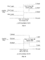
- FIGS. 9 and 10 show the closing and opening timing sequences respectively of the DPC.
- outside poles 16 and 17 close at peak line voltage and center pole 18 closes 90 electrical degrees later
- center pole 18 opens at zero line current and outside poles 16 and 17 open 90 electrical degrees later.
- FIG. 11 shows an assembly 400 incorporating Single Pole Switches (SPS).
- Assembly 400 includes an enclosure 20 , combined terminations and fixed contacts 6 , an extension of a moving contact carrier molding 21 , and attachment points 8 where screws fasten the line and motor cables.
- SPS Single Pole Switches
- FIG. 12 shows a cross-section along line AA-AA of assembly 400 .
- Assembly 400 includes moving contact 9 and spring 10 that provides contact pressure on closing.
- Iron magnet frame 11 supports magnet face 12 that mates with armature 13 .
- Coil 14 energizes iron magnet frame 11 and spring 15 is used to open magnet face 12 when coil 14 is de-energized.
- FIG. 13 shows a cross-section along line BB-BB of assembly 400 .
- Assembly 400 includes moving contact carrier molding 21 with spring 19 determining a pressure between moving contact 9 and fixed contact 6 .
- FIG. 14 shows a timing graph depicting an effect of the simultaneous connection of a three-phase supply to a delta connected motor.
- the curves depict a start for an unloaded delta motor with simultaneous closure of contactor poles.
- the bottom trace shows the severe torque pulsation and the middle curves show the very unbalanced three-phase line current.
- the top traces show the supply voltages from the moment of connection.
- FIG. 15 shows a timing graph depicting an effect of the two-step connection of a three-phase supply to the same delta connected motor. Torque pulsation is virtually eliminated and the motor supply currents are balanced with significantly lower peak currents.
- the top voltage plots show the two-step connection timing sequence.
- FIG. 16 illustrates an example set of connections for a motor in a wye-configuration.
- the contactor poles 1 , 2 , and 3 may be placed at either end of the windings.
- the factor ⁇ j multiplying the voltage space vector ⁇ S (t) in equation (6) means that the steady state flux ⁇ SS (t) rotates with ⁇ S (t) but lags behind in rotation by 90 degrees.
- the DC transient flux ⁇ DC is on the other hand fixed in orientation 90° ahead of the direction of the initial supply vector ⁇ S (t) at the moment of switch-on and only gradually decays away.
- FIG. 17 shows a space vector expressing the relations in equations (3), (5), & (6).
- the steady state flux ⁇ SS (t) has constant amplitude and rotates about the fixed center determined by the transient ⁇ DC which only decays away slowly.
- ⁇ SS (t) rotates, the presence of the DC flux ⁇ DC causes the amplitude of the resultant flux ⁇ (t) to oscillate strongly.
- the effect is strong torque pulsations and unbalanced currents until the DC transient decays away.
- the DC transient may be greatly reduced or eliminated if the supply connection process is performed in two steps. While the embodiments for different motor combinations below describe the use of specific supply phases, any combination of supply phases that maintain the same timing and voltage aspects for the two-step connection described below are equally suitable. Indeed, the two-step connection described relates to operations that result in additional current flow into the motor. It is equally suitable to connect one phase of the motor at any time prior to these steps as long as it does not result in current flow into the motor. In such a case, current would only flow at the time a second phase of the motor was connected to the supply and would be equivalent to both phases being connected concurrently.
- FIG. 18 shows a vector diagram for a two-step connection of contactor poles.
- the current flow through the motor windings builds up flux ⁇ 0 in the direction shown in FIG. 18 .
- ⁇ _ ⁇ ( t ) - j ⁇ u _ S ⁇ ( t ) ⁇ lagging 90° behind the instantaneous position at orientation ⁇ of the voltage space vector ⁇ S (t) at the moment when supply phase A is connected. Thereafter, the voltage ⁇ S (t) and the flux ⁇ (t) synchronously, 90° apart, in their steady state without torque pulsations or excessive peak currents.
- u SD 2 ⁇ 3( u SA ⁇ 0.5 ⁇ u SB ⁇ 0.5 ⁇ u SC )
- u SQ 1/ ⁇ square root over (3) ⁇ ( u SB ⁇ u SC ) (7)
- u SA , u SB , u SC are the voltages across the three windings.
- FIG. 19 shows the phase voltage waveforms showing three of the six possible connection timings for two-step closing of a wye-configured motor.
- the vertical lines denote the times when at least one phase of the supply is expected to be connected such that current flow into the motor windings is increased.
- the delay represented by ⁇ represents the period between the first connections resulting in current flow in the motor and the second connections resulting in all phases of the supply being connected the motor.
- FIG. 20 illustrates a delta-configured motor with contactor poles connected outside the motor windings.
- u CA ⁇ square root over (3) ⁇ u S sin( ⁇ t+ ⁇ / 2)
- u SA ⁇ square root over (3) ⁇ u S sin( ⁇ t+ ⁇ / 2)
- u SB ⁇ square root over (3) ⁇ /2 u S sin( ⁇ t+ ⁇ / 2)
- u SC u SB (16)
- FIG. 21 shows a delta-configured motor with contactor poles inside the motor windings. If the contactor poles for delta operation are placed within the delta (as is normal for wye-delta starting), the current flow in at least one winding can be achieved by connecting one phase of the motor to the supply as shown in FIG. 21 . In FIG. 21 , current flows in winding A when pole 1 connects the switched side of winding A to the phase C supply.
- Single Pole Switches have a DC operated electromagnet with electronic coil control operating a single set of fixed and moving contacts in an individual enclosure per FIGS. 11 and 12 .
- Armature 13 in FIG. 12 is acted upon by a magnetic field produced by the electromagnet coil 14 to control the connection and disconnection of contacts 6 and 9 .
- They are used to connect individual phases of the supply to the motor as described in the three motor connection configurations described earlier. Because they allow for the independent control over the connection of each phase of the supply to a motor, they are well suited for use with a two-step closure process.
- the three contactor poles 1 , 2 , and 3 must be closed in the correct sequence at the desired points on the supply waveforms.
- two poles must connect the motor to the supply such that current first begins to flow in at least one motor winding at the peak voltage amplitude (approximately 90 degrees after the line-to-line zero-crossing of the two phases being connected). This can be accomplished by concurrently connecting both poles at this point on the supply waveform or by closing one pole at an earlier time and the other at this point on the supply waveform. Both approaches are equally suitable, though the latter may prove easier to implement.
- the remaining pole should be closed approximately 90 degrees later on the supply waveform.
- the three contactor poles 1 , 2 , and 3 must be closed in the correct sequence at the desired points on the supply waveforms.
- one pole must connect the motor to the supply such that, current first begins to flow in one motor winding at a point 30 degrees prior to the peak voltage amplitude (approximately 60 degrees after the line-to-line zero-crossing of the two phases being connected).
- the remaining two poles should be closed approximately 120 degrees later on the supply waveform.
- This contact closure time represents the time from energizing the SPS magnetic coil until the contacts allow current to flow from the supply to the motor. This information can typically be gained by characterizing the design after it is in production.
- t CE t ZC +d Offset ⁇ t Degree ⁇ t CC
- t CE the time at which the coil is to be energized
- t ZC the time of the zero-cross the estimated time is to be based on
- d Offset is the offset in degrees of the supply waveform from t ZC that the connection of the supply to the motor is desired
- t Degree is the time period equal to one degree of the supply waveform
- t CC is the period from when the SPS coil is energized to when the contacts allow current to flow from the supply to the motor.
- Delayed Pole Contactor An alternative to Single Pole Switches in implementing the two-step connection process is a Delayed Pole Contactor.
- This design is a three-pole contactor with the contacts arranged to close asynchronously at the preferred angles for the two-step connection process.
- the center pole is magnetically arranged to close later than the outer poles.
- the moving contact carrier has contact springs operating on contacts assembled in pole windows.
- the center contact is offset from the contacts of the two outer poles by having the center window smaller by the amount x.
- Using identical contacts and modifying the molded contact carrier gives the desired early closure of the outer poles.
- the contactor electromagnet is controlled so as to stall in this interim step one position.
- the contact gap h in the center pole is of sufficient dielectric strength to avoid conduction for approximately a quarter of the mains cycle following the contact closure of the outer two poles.
- This gap h is typically 0.5 mm to 1 mm depending on size of contactor.
- the power into the contactor-operating coil is controlled, such that in conjunction with the center contact physical offset and other contactor dynamics, so as to close the outer poles to this stalled position for a period equal to 90 electrical degrees of the supply frequency.
- the power into the contactor operating coil is then adjusted such that the contact springs in all poles are compressed past distance d, positioning the DPC in its final closed position.
- the power into the contactor-operating coil is reduced to a level sufficient to keep the contactor in the closed position.
- FIG. 24 shows a motor circuit using a three-pole Delayed Pole Contactor (DPC) while FIG. 25 shows a motor circuit using Single Pole Switches (SPS).
- a switch 53 is coupled to a controller 50 .
- Controller 50 regulates power to the respective actuator assembly of the respective contactor in order to engage and disengage the contacts in accordance with the two-step connection.
- Controller 50 operates in association with a voltage zero-crossing monitor in regulating the power being applied.
Landscapes
- Engineering & Computer Science (AREA)
- Power Engineering (AREA)
- Physics & Mathematics (AREA)
- Electromagnetism (AREA)
- Motor And Converter Starters (AREA)
- Control Of Stepping Motors (AREA)
- Control Of Multiple Motors (AREA)
- Control Of Ac Motors In General (AREA)
Priority Applications (10)
| Application Number | Priority Date | Filing Date | Title |
|---|---|---|---|
| US13/815,863 US9590536B2 (en) | 2013-03-15 | 2013-03-15 | Two-step connection of electric motors by means of electromagnetic switches |
| US14/201,169 US9396898B2 (en) | 2013-03-15 | 2014-03-07 | Multipole electromechanical switching device |
| CN201810011081.3A CN108054055B (zh) | 2013-03-15 | 2014-03-17 | 机电开关装置 |
| EP14160333.2A EP2779194B1 (fr) | 2013-03-15 | 2014-03-17 | Connexion en deux étapes de moteurs électriques au moyen de commutateurs électromagnétiques |
| CN201410098783.1A CN104051195B (zh) | 2013-03-15 | 2014-03-17 | 多极机电开关装置 |
| CN201410099213.4A CN104052338B (zh) | 2013-03-15 | 2014-03-17 | 借助于电磁开关对电动机的两步连接的装置及方法 |
| EP14160339.9A EP2787518B1 (fr) | 2013-03-15 | 2014-03-17 | Connexion en deux étapes de moteurs électriques au moyen de commutateurs électromagnétiques |
| CN201811208539.0A CN109546894B (zh) | 2013-03-15 | 2014-03-17 | 借助于电磁开关对电动机的两步连接的方法和设备 |
| US15/214,142 US9805883B2 (en) | 2013-03-15 | 2016-07-19 | Multipole electromechanical switching device |
| US15/797,696 US10347440B2 (en) | 2013-03-15 | 2017-10-30 | Multipole electromechanical switching device |
Applications Claiming Priority (1)
| Application Number | Priority Date | Filing Date | Title |
|---|---|---|---|
| US13/815,863 US9590536B2 (en) | 2013-03-15 | 2013-03-15 | Two-step connection of electric motors by means of electromagnetic switches |
Related Child Applications (1)
| Application Number | Title | Priority Date | Filing Date |
|---|---|---|---|
| US14/201,169 Continuation US9396898B2 (en) | 2013-03-15 | 2014-03-07 | Multipole electromechanical switching device |
Publications (2)
| Publication Number | Publication Date |
|---|---|
| US20140265995A1 US20140265995A1 (en) | 2014-09-18 |
| US9590536B2 true US9590536B2 (en) | 2017-03-07 |
Family
ID=50391004
Family Applications (1)
| Application Number | Title | Priority Date | Filing Date |
|---|---|---|---|
| US13/815,863 Active 2033-08-23 US9590536B2 (en) | 2013-03-15 | 2013-03-15 | Two-step connection of electric motors by means of electromagnetic switches |
Country Status (3)
| Country | Link |
|---|---|
| US (1) | US9590536B2 (fr) |
| EP (1) | EP2787518B1 (fr) |
| CN (2) | CN109546894B (fr) |
Cited By (2)
| Publication number | Priority date | Publication date | Assignee | Title |
|---|---|---|---|---|
| US20170358413A1 (en) * | 2016-06-14 | 2017-12-14 | Fuji Electric Fa Components & Systems Co., Ltd. | Contact device and electromagnetic contactor using same |
| US10153115B2 (en) * | 2017-01-11 | 2018-12-11 | Fuji Electric Fa Components & Systems Co., Ltd. | Electromagnetic contactor |
Families Citing this family (20)
| Publication number | Priority date | Publication date | Assignee | Title |
|---|---|---|---|---|
| US9748873B2 (en) | 2014-11-06 | 2017-08-29 | Rockwell Automation Technologies, Inc. | 5-pole based wye-delta motor starting system and method |
| US10074497B2 (en) | 2014-11-06 | 2018-09-11 | Rockwell Automation Technologies, Inc. | Operator coil parameter based electromagnetic switching |
| US9772381B2 (en) | 2014-11-06 | 2017-09-26 | Rockwell Automation Technologies, Inc. | Synchronized reapplication of power for driving an electric motor |
| US10141143B2 (en) | 2014-11-06 | 2018-11-27 | Rockwell Automation Technologies, Inc. | Wear-balanced electromagnetic motor control switching |
| US10361051B2 (en) | 2014-11-06 | 2019-07-23 | Rockwell Automation Technologies, Inc. | Single pole, single current path switching system and method |
| US9806642B2 (en) | 2014-11-06 | 2017-10-31 | Rockwell Automation Technologies, Inc. | Modular multiple single-pole electromagnetic switching system and method |
| US9806641B2 (en) | 2014-11-06 | 2017-10-31 | Rockwell Automation Technologies, Inc. | Detection of electric motor short circuits |
| US9722513B2 (en) | 2014-11-06 | 2017-08-01 | Rockwell Automation Technologies, Inc. | Torque-based stepwise motor starting |
| CN104319186B (zh) * | 2014-11-17 | 2017-11-17 | 蒋胜泉 | 可控制多负载的时序继电器 |
| DE112015005461B4 (de) * | 2014-12-05 | 2023-06-15 | Omron Corporation | Elektromagnetisches Relais |
| JP2016110843A (ja) | 2014-12-05 | 2016-06-20 | オムロン株式会社 | 電磁継電器 |
| JP6414453B2 (ja) | 2014-12-05 | 2018-10-31 | オムロン株式会社 | 電磁継電器 |
| JP6388564B2 (ja) * | 2015-07-09 | 2018-09-12 | 三菱電機株式会社 | 電動機応用製品 |
| US10134551B2 (en) * | 2016-09-21 | 2018-11-20 | Astronics Advanced Electronic Systems Corp. | Galvanically isolated hybrid contactor |
| US10395857B2 (en) * | 2017-08-04 | 2019-08-27 | Rockwell Automation Technologies, Inc. | POW switching device with enhanced programming |
| US10396689B2 (en) * | 2017-08-04 | 2019-08-27 | Rockwell Automation Technologies, Inc. | PCB-based motor starter |
| US10396688B2 (en) * | 2017-08-04 | 2019-08-27 | Rockwell Automation Technologies, Inc. | PCB motor controller with POW switching |
| DE102017220503B3 (de) * | 2017-11-16 | 2019-01-17 | Te Connectivity Germany Gmbh | Doppelt unterbrechender Schalter |
| US11496079B2 (en) * | 2019-08-29 | 2022-11-08 | Rockwell Automation Technologies, Inc. | Compact motor starter |
| JP7304786B2 (ja) * | 2019-10-04 | 2023-07-07 | 日立Astemo株式会社 | 回転機駆動システム及び車両 |
Citations (15)
| Publication number | Priority date | Publication date | Assignee | Title |
|---|---|---|---|---|
| DE951020C (de) | 1951-11-25 | 1956-10-18 | Siemens Ag | Drehstromschuetz fuer synchrones Ausschalten, dessen Kontakte zwecks Vermeidung von Schaltfeuer kurz vor dem Nulldurchgang des Stromes geoeffnet werden |
| US4471183A (en) | 1981-11-02 | 1984-09-11 | Siemens Aktiengesellschaft | Three-phase switchgear |
| JPS63184225A (ja) | 1987-01-27 | 1988-07-29 | 富士電機株式会社 | 電磁接触器 |
| US5430599A (en) * | 1993-03-18 | 1995-07-04 | Hydro-Quebec | System for opening/closing circuit breakers |
| US20010022508A1 (en) | 2000-02-23 | 2001-09-20 | Juergen Lang | Method for operating an electric generator/motor system |
| CN1354885A (zh) | 1999-05-11 | 2002-06-19 | 株式会社因特文讯 | 用于星形-三角形接线的磁接触器 |
| US20050013085A1 (en) | 2003-06-28 | 2005-01-20 | Kinsella James J. | Method and system of controlling asynchronous contactors for a multi-phase electric load |
| US6956728B2 (en) * | 2003-02-28 | 2005-10-18 | Eaton Corporation | Method and apparatus to control modular asynchronous contactors |
| WO2006035194A2 (fr) | 2004-09-27 | 2006-04-06 | Unsworth Peter J | Demarrage et commutation de moteur |
| US7196434B2 (en) | 2003-03-21 | 2007-03-27 | Eaton Corporation | Modular contactor assembly having independently controllable contractors |
| US7317264B2 (en) * | 2003-11-25 | 2008-01-08 | Eaton Corporation | Method and apparatus to independently control contactors in a multiple contactor configuration |
| US7576957B2 (en) | 2006-05-01 | 2009-08-18 | Eaton Corporation | Circuit interrupter including point-on-wave controller and voltage sensors |
| CN201365218Y (zh) | 2009-02-25 | 2009-12-16 | 河海大学 | 一种三相交流电机相序控制器 |
| US7977824B2 (en) * | 2007-02-02 | 2011-07-12 | Abb Research Ltd. | Switching device, use thereof and a method for switching |
| CN102368672A (zh) | 2011-07-19 | 2012-03-07 | 株洲变流技术国家工程研究中心有限公司 | 一种电动机软起动仿真装置及其方法 |
Family Cites Families (1)
| Publication number | Priority date | Publication date | Assignee | Title |
|---|---|---|---|---|
| WO2011116488A1 (fr) * | 2010-03-22 | 2011-09-29 | Siemens Aktiengesellschaft | Procédé et appareil permettant de supprimer le courant d'appel d'un transformateur |
-
2013
- 2013-03-15 US US13/815,863 patent/US9590536B2/en active Active
-
2014
- 2014-03-17 CN CN201811208539.0A patent/CN109546894B/zh active Active
- 2014-03-17 EP EP14160339.9A patent/EP2787518B1/fr active Active
- 2014-03-17 CN CN201410099213.4A patent/CN104052338B/zh active Active
Patent Citations (19)
| Publication number | Priority date | Publication date | Assignee | Title |
|---|---|---|---|---|
| DE951020C (de) | 1951-11-25 | 1956-10-18 | Siemens Ag | Drehstromschuetz fuer synchrones Ausschalten, dessen Kontakte zwecks Vermeidung von Schaltfeuer kurz vor dem Nulldurchgang des Stromes geoeffnet werden |
| US4471183A (en) | 1981-11-02 | 1984-09-11 | Siemens Aktiengesellschaft | Three-phase switchgear |
| JPS63184225A (ja) | 1987-01-27 | 1988-07-29 | 富士電機株式会社 | 電磁接触器 |
| US5430599A (en) * | 1993-03-18 | 1995-07-04 | Hydro-Quebec | System for opening/closing circuit breakers |
| CN1354885A (zh) | 1999-05-11 | 2002-06-19 | 株式会社因特文讯 | 用于星形-三角形接线的磁接触器 |
| US20010022508A1 (en) | 2000-02-23 | 2001-09-20 | Juergen Lang | Method for operating an electric generator/motor system |
| US6967549B2 (en) | 2003-02-28 | 2005-11-22 | Eaton Corporation | Method and apparatus to control modular asynchronous contactors |
| US6956728B2 (en) * | 2003-02-28 | 2005-10-18 | Eaton Corporation | Method and apparatus to control modular asynchronous contactors |
| US7196434B2 (en) | 2003-03-21 | 2007-03-27 | Eaton Corporation | Modular contactor assembly having independently controllable contractors |
| US20050013085A1 (en) | 2003-06-28 | 2005-01-20 | Kinsella James J. | Method and system of controlling asynchronous contactors for a multi-phase electric load |
| US7224557B2 (en) * | 2003-06-28 | 2007-05-29 | Eaton Corporation | Method and system of controlling asynchronous contactors for a multi-phase electric load |
| US7317264B2 (en) * | 2003-11-25 | 2008-01-08 | Eaton Corporation | Method and apparatus to independently control contactors in a multiple contactor configuration |
| WO2006035194A2 (fr) | 2004-09-27 | 2006-04-06 | Unsworth Peter J | Demarrage et commutation de moteur |
| US7812563B2 (en) * | 2004-09-27 | 2010-10-12 | Peter Unsworth | Motor starting and switching |
| US8305024B2 (en) * | 2004-09-27 | 2012-11-06 | Peter Unsworth | Motor starting and switching |
| US7576957B2 (en) | 2006-05-01 | 2009-08-18 | Eaton Corporation | Circuit interrupter including point-on-wave controller and voltage sensors |
| US7977824B2 (en) * | 2007-02-02 | 2011-07-12 | Abb Research Ltd. | Switching device, use thereof and a method for switching |
| CN201365218Y (zh) | 2009-02-25 | 2009-12-16 | 河海大学 | 一种三相交流电机相序控制器 |
| CN102368672A (zh) | 2011-07-19 | 2012-03-07 | 株洲变流技术国家工程研究中心有限公司 | 一种电动机软起动仿真装置及其方法 |
Non-Patent Citations (3)
| Title |
|---|
| Extended European Search Report for 14160339.9 mailed Dec. 8, 2015. |
| Office Action for CN Application No. 20140098783.1 mailed Apr. 13, 2016. |
| Office Action for CN Application No. 201410099213.4 mailed Apr. 13, 2016. |
Cited By (3)
| Publication number | Priority date | Publication date | Assignee | Title |
|---|---|---|---|---|
| US20170358413A1 (en) * | 2016-06-14 | 2017-12-14 | Fuji Electric Fa Components & Systems Co., Ltd. | Contact device and electromagnetic contactor using same |
| US10170261B2 (en) * | 2016-06-14 | 2019-01-01 | Fuji Electric Fa Components & Systems Co., Ltd. | Contact device and electromagnetic contactor using same |
| US10153115B2 (en) * | 2017-01-11 | 2018-12-11 | Fuji Electric Fa Components & Systems Co., Ltd. | Electromagnetic contactor |
Also Published As
| Publication number | Publication date |
|---|---|
| EP2787518A2 (fr) | 2014-10-08 |
| US20140265995A1 (en) | 2014-09-18 |
| EP2787518B1 (fr) | 2018-07-11 |
| EP2787518A3 (fr) | 2016-01-06 |
| CN104052338A (zh) | 2014-09-17 |
| CN104052338B (zh) | 2018-11-16 |
| CN109546894A (zh) | 2019-03-29 |
| CN109546894B (zh) | 2022-04-05 |
Similar Documents
| Publication | Publication Date | Title |
|---|---|---|
| US9590536B2 (en) | Two-step connection of electric motors by means of electromagnetic switches | |
| US10347440B2 (en) | Multipole electromechanical switching device | |
| US7224557B2 (en) | Method and system of controlling asynchronous contactors for a multi-phase electric load | |
| EP1820259B1 (fr) | Demarrage et commutation de moteur | |
| US10345381B2 (en) | Cleaning and motor heating electromagnetic motor control switching | |
| US10361051B2 (en) | Single pole, single current path switching system and method | |
| US10141143B2 (en) | Wear-balanced electromagnetic motor control switching | |
| US9806641B2 (en) | Detection of electric motor short circuits | |
| US20160134210A1 (en) | Modular multiple single-pole electromagnetic switching system and method | |
| US9722513B2 (en) | Torque-based stepwise motor starting | |
| Lee et al. | Doubly-fed machine with wireless power transfer ability |
Legal Events
| Date | Code | Title | Description |
|---|---|---|---|
| AS | Assignment |
Owner name: POINTWAVE LLC, TENNESSEE Free format text: ASSIGNMENT OF ASSIGNORS INTEREST;ASSIGNOR:KINSELLA, JAMES J.;REEL/FRAME:031321/0457 Effective date: 20130927 Owner name: KINSELLA, JAMES J., TENNESSEE Free format text: ASSIGNMENT OF ASSIGNORS INTEREST;ASSIGNOR:UNSWORTH, PETER J., DR.;REEL/FRAME:031321/0359 Effective date: 20130926 Owner name: ROCKWELL AUTOMATION TECHNOLOGIES, INC., WISCONSIN Free format text: ASSIGNMENT OF ASSIGNORS INTEREST;ASSIGNOR:POINTWAVE LLC;REEL/FRAME:031321/0530 Effective date: 20130930 |
|
| AS | Assignment |
Owner name: ROCKWELL AUTOMATION TECHNOLOGIES, INC., WISCONSIN Free format text: ASSIGNMENT OF ASSIGNORS INTEREST;ASSIGNORS:KINSELLA, JAMES J.;UNSWORTH, PETER;SIGNING DATES FROM 20140401 TO 20140514;REEL/FRAME:033060/0822 |
|
| STCF | Information on status: patent grant |
Free format text: PATENTED CASE |
|
| MAFP | Maintenance fee payment |
Free format text: PAYMENT OF MAINTENANCE FEE, 4TH YEAR, LARGE ENTITY (ORIGINAL EVENT CODE: M1551); ENTITY STATUS OF PATENT OWNER: LARGE ENTITY Year of fee payment: 4 |
|
| MAFP | Maintenance fee payment |
Free format text: PAYMENT OF MAINTENANCE FEE, 8TH YEAR, LARGE ENTITY (ORIGINAL EVENT CODE: M1552); ENTITY STATUS OF PATENT OWNER: LARGE ENTITY Year of fee payment: 8 |