EP2789574B1 - Machine de remplissage aseptique et procédé de traitement de bouchons de récipients avec une machine de remplissage aseptique - Google Patents
Machine de remplissage aseptique et procédé de traitement de bouchons de récipients avec une machine de remplissage aseptique Download PDFInfo
- Publication number
- EP2789574B1 EP2789574B1 EP14150714.5A EP14150714A EP2789574B1 EP 2789574 B1 EP2789574 B1 EP 2789574B1 EP 14150714 A EP14150714 A EP 14150714A EP 2789574 B1 EP2789574 B1 EP 2789574B1
- Authority
- EP
- European Patent Office
- Prior art keywords
- treatment section
- treatment
- container
- container caps
- caps
- Prior art date
- Legal status (The legal status is an assumption and is not a legal conclusion. Google has not performed a legal analysis and makes no representation as to the accuracy of the status listed.)
- Active
Links
Images
Classifications
-
- B—PERFORMING OPERATIONS; TRANSPORTING
- B67—OPENING, CLOSING OR CLEANING BOTTLES, JARS OR SIMILAR CONTAINERS; LIQUID HANDLING
- B67B—APPLYING CLOSURE MEMBERS TO BOTTLES JARS, OR SIMILAR CONTAINERS; OPENING CLOSED CONTAINERS
- B67B3/00—Closing bottles, jars or similar containers by applying caps
- B67B3/003—Pretreatment of caps, e.g. cleaning, steaming, heating or sterilizing
-
- B—PERFORMING OPERATIONS; TRANSPORTING
- B67—OPENING, CLOSING OR CLEANING BOTTLES, JARS OR SIMILAR CONTAINERS; LIQUID HANDLING
- B67B—APPLYING CLOSURE MEMBERS TO BOTTLES JARS, OR SIMILAR CONTAINERS; OPENING CLOSED CONTAINERS
- B67B3/00—Closing bottles, jars or similar containers by applying caps
- B67B3/02—Closing bottles, jars or similar containers by applying caps by applying flanged caps, e.g. crown caps, and securing by deformation of flanges
- B67B3/06—Feeding caps to capping heads
- B67B3/062—Feeding caps to capping heads from a magazine
-
- B—PERFORMING OPERATIONS; TRANSPORTING
- B67—OPENING, CLOSING OR CLEANING BOTTLES, JARS OR SIMILAR CONTAINERS; LIQUID HANDLING
- B67C—CLEANING, FILLING WITH LIQUIDS OR SEMILIQUIDS, OR EMPTYING, OF BOTTLES, JARS, CANS, CASKS, BARRELS, OR SIMILAR CONTAINERS, NOT OTHERWISE PROVIDED FOR; FUNNELS
- B67C7/00—Concurrent cleaning, filling, and closing of bottles; Processes or devices for at least two of these operations
- B67C7/0073—Sterilising, aseptic filling and closing
Definitions
- the present invention relates to an aseptic filling according to the preamble of claim 1 for the aseptic filling of liquids in containers and a method for treating container closures in an aseptic filling for aseptically filling liquids in containers, preferably for sterilizing plastic screw closures for beverage containers in a beverage filling plant.
- the plastic closures are sterilized before sealing.
- different treatment options are available, such as, for example, physical sterilization by means of hot water, saturated steam, UV irradiation or plasma.
- a chemical degerming with hydrogen peroxide, peracetic acid, chlorine dioxide or ozone can be performed. Combinations of these different sterilization methods are also conceivable.
- the filling process into the containers and the closing of the completely filled containers takes place, in particular in the case of aseptic filling and in particular in cold aseptic filling, within a clean room.
- This is a space substantially sealed from the environment, in which a defined germ-free atmosphere prevails, and whose inner surfaces are correspondingly cleaned and sterilized regularly.
- a cold aseptic filling allows a particularly long shelf life of the bottled products and is used, for example, for the filling of dairy products.
- the sterilization of the closures in front of the capper usually takes place in a sterilization chamber, into which the respective closures are introduced via a gutter system, and in which the corresponding treatment medium is present in order to achieve the sterilization of the closures.
- Such a device is for example from the WO 2010/073064 A1 in which the individual container closures are subjected to a heat treatment.
- the closures are pushed into the sterilization chamber via an actuator, which then exerts a corresponding dynamic pressure on the closures already in the sterilization chamber in such a way that the closures are driven through the sterilization chamber and exit at the end from the sterilization chamber.
- a disadvantage of the known systems for sterilization sterilization is that in an interruption of the influx of fully filled containers, the closures present downstream of the sterilization chamber in a corresponding feed chute are usually discarded because they are fed to the capper regardless of the influx of containers and then ejected in the capper if they are not screwed onto a container. This results in a loss of plastic closures in the event of a disturbance in the container supply, in particular when supplying such a plastic closure to a container gap in the production process.
- the WO 2010/012334 A1 describes a transport route for conveying caps for closing bottles or containers.
- the EP 2 687 478 A1 is an interim publication and thus only relevant to the question of novelty; It describes an apparatus and method for treating closures for containers.
- the US 2013/0004368 A1 describes an apparatus and method for sterilizing caps.
- the US 2005/0169796 A1 describes an aseptic filler according to the preamble of claim 1 with a device for sterilizing closures.
- the DE 10 2005 032 322 A1 describes a method and a machine for closing bottles with sterile caps.
- the FR 2 765 566 A1 describes a system for filling a product into closable containers and a device for storing the closures.
- the WO 98/47770 A1 describes a system for blow molding, filling and sealing of containers.
- the aseptic filler for aseptically filling liquids into containers comprises a capper arranged in a clean room for closing filled containers and a device for treating container closures, also more generally referred to as shaped parts, preferably for sterilizing plastic screw closures for beverage containers.
- the device comprises a treatment line for treating the mold parts with a treatment medium, and a feed device arranged upstream of the treatment line for feeding molded parts to the treatment line.
- a discharge device arranged downstream of the treatment section is provided for discharging molded parts from the treatment section.
- the loss of mold parts can be minimized by interrupting the supply of containers to be closed or also at the end of the respective production, while at the same time ensuring that each individual molded part has the same receives each necessary treatment time in the treatment section and thus, for example, the prescribed sterilization is achieved.
- the feeding device is controlled so that it gives up the individual molded part in time to the treatment route.
- the molding then passes through the treatment section and, after the expiration of the predetermined treatment time or as needed, passed over the discharge device of the respective downstream machine station, such as a capper in an aseptic filler.
- each molding that is output by the discharge device can also be further processed according to directly.
- the molded part can thus be correspondingly fed so that each container is accurately provided with a plastic screw cap.
- the treatment time which passes through a molded part in the treatment section, can be adjusted via a corresponding parameterization of the triggering of the feed device relative to the triggering of the discharge device.
- the feed device and / or the discharge device are preferably driven by a stepping motor in such a way that a partial feeding or a partial exact discharge of the respective molded parts is made possible. In this way, moldings can be partially supplied to the treatment line and discharged from this again.
- the treatment section is arranged in a treatment chamber which surrounds the treatment section, and in which a corresponding atmosphere with the treatment medium can be established.
- the feed device and / or the discharge device are arranged in the treatment chamber, preferably at the upstream or downstream end of the treatment section.
- An increase in efficiency in carrying out the treatment in the treatment section can be achieved by at least two parallel grooves, so that a simultaneous treatment of at least two parallel guided moldings can be achieved.
- an emptying device is arranged according to the invention above the feeder, by means of which a molding supply completely can be emptied. In this way, it is possible to completely emptying a possibly existing molded parts storage without the moldings all having to go through the treatment section.
- a sensor downstream of the supply device is preferably provided so that it serves to detect a backlog of molded parts in the treatment section.
- the sensor can be provided for example in the form of a light barrier or another sensor so that it either detects the passage of the molded part through the treatment section, or only outputs a corresponding signal at a permanent interruption by a fixed molding. It can be determined via this sensor whether the molded parts dispensed on the treatment path via the supply device actually pass through the treatment path or whether there is a backflow, ie the molded parts have jammed within the treatment path.
- a sensor is further preferably provided downstream of the discharge device, by means of which a backwater can be detected in a transfer region for the mold parts downstream of the discharge device.
- Three operating states can be provided via these sensors and a corresponding stepper motor control of the feed device and the discharge device.
- a first operating state all stepper motors are switched off, so that a promotion and treatment of the moldings does not take place.
- the stepper motors are each driven via a reference point of a parallel or upstream process, that is, for example, when passing through a specific machine angle of a parallel or upstream unit.
- This unit may for example be a filler of a beverage filling plant.
- the control of the stepping motor is correspondingly triggered so that a closure is introduced via the feeding device into the treatment line.
- passing through a second reference point of the stepper motor of the discharge device is actuated so that the corresponding molding is discharged and passed to the subsequent capper.
- the stepper motors move per machine cycle or pulse from the corresponding system control by an imaginary revolution.
- the control of the discharge device relative to the feed device can also be carried out via a time control, which always triggers the feeding of a molded part into the treatment section by at least the minimum treatment time, than the actual discharge process.
- each closure is adequately treated and, for example, correctly sterilized closures are used accordingly.
- this mode of operation makes it possible that a discharge device made of the insulator, for example an aseptic system, is no longer necessary, since here it is no longer necessary to discharge any closures.
- a discharge device made of the insulator for example an aseptic system
- costs can be saved and on the other hand the plant complexity can be reduced, whereby danger potentials in microbiological regard are reduced.
- the device for the treatment of the moldings can be arranged outside the clean room.
- the sensors and motors which are used to drive the feeder and the discharge device can be mounted outside of the clean room, which on the one hand the sterility of the respective insulator is not compromised and on the other hand, the life of the drives and the sensor can be increased because they are not exposed to the aggressive cleaning cycles inside the insulator.
- the treatment section can be used with all known treatment media, for example with hydrogen peroxide, as well as with a peracetic acid immersion bath.
- the device for the treatment of container closures outside the clean room of the aseptic filling is arranged.
- the shaped parts are preferably fed in part by means of the supply device of the treatment section and / or discharged in part by means of the discharge device.
- the feeding of molded parts to the treatment section and / or the discharge of molded parts from the treatment section over the machine cycle is triggered, preferably in the presence of a trigger signal, particularly preferably taking into account a minimum treatment time.
- the feeding of molded parts to the treatment section and / or the discharge of molded parts from the treatment section can also be triggered when a reference position is reached in a parallel process, preferably taking into account a minimum treatment time.
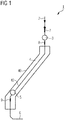
- FIG. 1 schematically shows a device 1 for treating moldings, here shown in the form of a device for sterilizing plastic screw caps for closing beverage containers in a beverage filling plant.
- a molding supply 2 via which the individual moldings are supplied from a supply of moldings, the moldings go to a feeding device 3, which is adapted to the partially precise feeding of moldings to a treatment section 4.
- the partially accurate feed is achieved for example by a control via a stepper motor.
- the treatment section 4 is accommodated in a treatment chamber 40 and is designed in the form of a schematically indicated channel 42, through which the molded parts, which are supplied via the supply device 3, slide therethrough.
- the channel 42 and thus also the treatment chamber 40 is arranged downhill, such that the respective molded parts pass through the groove 42 due to their own weight.
- At least two grooves arranged parallel to one another are provided, so that at least two molded parts can be treated parallel to one another.
- a discharge device 5 Downstream of the treatment section 4, a discharge device 5 is provided, which serves for partial removal of the respective mold parts to a corresponding transfer area 6.
- the transfer area 6 is followed by a further treatment station. In the case of a bottling plant, this is typically followed by the corresponding capper, which is supplied with the then sterilized plastic screw caps.
- the feed device 3 is arranged correspondingly upstream of the treatment section 4 and the discharge device 5 is arranged downstream of the treatment section 4. Accordingly, the supply of the respective molded parts into the treatment section 4 can be effected in part via the supply device 3.
- the downstream of the treatment section 4 arranged discharge device 5 allows demand-controlled transfer of the respective molding to the transfer device 6 always exactly when a respective molding is needed here.
- an individual plastic screw cap When used as a sterilization device for plastic closures in a beverage bottling plant, an individual plastic screw cap is accordingly placed on the treatment line 4 for each filled and sealed container via the feeding device 3 and, after passing through the corresponding treatment time, synchronized via the discharge device 5 to the respective capper, that the corresponding container to be closed can be closed. If there is no container to be sealed, no plastic screw cap is sterilized and discharged. In this way it can be avoided that, for example in the Interruption of the container flow must be discarded by a prior discharge of defective containers, closures that had been supplied to the capper.
- an emptying device 7 is further provided above the feeding device 3, which can be opened after completion of the production process and by means of which the molded parts from the molded part storage, which are supplied via the molding supply 2, can be completely emptied.
- a first sensor 8 is preferably provided downstream of the feed device 3 in order to be able to detect a backflow of molded parts in the treatment section 4.
- a further sensor 9 is preferably provided downstream of the discharge device 5 in order to be able to detect the detection of a backflow in a transfer region 6.
- the sensors 8, 9 can be used to monitor whether the molded parts pass through the corresponding areas of the system and, in particular, the treatment section 4 in the form of the channel 42, or whether there is possibly a backlog or jamming of a molded part. Via the sensor 9 it is also possible to check whether the output of the molded parts to the transfer area 6 takes place in the predetermined manner, or whether, for example a backwater in the transfer area 6 is present, which suggests a jamming or other jam of the molded parts in the transfer area 6.
- the feed device 3 and the discharge device 5 are preferably driven by a stepping motor, by means of which a partially precise feeding of molded parts into the treatment section 4 and a partial removal of molded parts via the discharge device 5 is possible.
- the feed device 3 and the discharge device 5 can be controlled in different ways.
- the feed device 3 in connection with a beverage filling system, can be actuated when a particular container to be filled is inserted into the corresponding filling device, and when the corresponding container has passed through a further section of the treatment angle or moves in the inlet towards the capper, the discharge device 5 are operated.
- the discharge device 5 are operated at predetermined points within the feed of the containers to be closed.
- the feeding of a molded part into the treatment section 4 is triggered and, after passing through a second reference point, the discharge of the molded part from the treatment section 4 is triggered.
- the treatment time which varies with the machine speed in this operating mode, must be taken into consideration. The minimum treatment time must not be undercut.
- triggering of the feed device 3 and the discharge device 5 can take place, for example, via the machine cycle, wherein the machine cycle is delayed either for the feed device or for the discharge device in accordance with the intended treatment time.
- a control over the general machine cycle is further necessary that a corresponding trigger signal is present, according to which closures are actually passed to the capper, in order to avoid unnecessary discarding container closures in the presence of a disturbance in the container flow.
- the sensor signal of the sensors 8 and 9 continue to be considered in order to ensure that a backwater is not present and correspondingly a free flow of the molded parts takes place through the treatment section 4 into the transfer area 6.
Landscapes
- Engineering & Computer Science (AREA)
- Mechanical Engineering (AREA)
- Filling Of Jars Or Cans And Processes For Cleaning And Sealing Jars (AREA)
- Sealing Of Jars (AREA)
Claims (14)
- Appareil de remplissage aseptique pour le remplissage aseptique de liquides dans des récipients, comprenant un dispositif de fermeture agencé dans une salle blanche pour fermer des récipients remplis et un dispositif (1) pour traiter des bouchons de récipients, de préférence pour stériliser des bouchons filetés en matière plastique pour récipients de boissons, comprenant une voie de traitement (4) pour traiter les bouchons de récipients avec un agent de traitement,
un dispositif d'alimentation (3) agencé en amont de la voie de traitement (4) pour acheminer des bouchons de récipients à la voie de traitement (4) et
un dispositif de rejet (5) agencé en aval de la voie de traitement (4) qui permet, en cas de besoin, un transfert du bouchon de récipient respectif à un dispositif de transfert (6) si et seulement si une pièce moulée respective y est nécessaire,
caractérisé en ce que :
le dispositif (1) présente en outre un dispositif d'évacuation (7) pour évacuer une alimentation de bouchons de récipients (2) en amont du dispositif d'alimentation (3). - Appareil de remplissage aseptique selon la revendication 1, caractérisé en ce que le dispositif d'alimentation (3) et/ou le dispositif de rejet (5) est ou sont actionnés via un moteur pas à pas.
- Appareil de remplissage aseptique selon la revendication 1 ou 2, caractérisé en ce que la voie de traitement (4) est agencée dans une chambre de traitement (40) et/ou la voie de traitement (4) est formée d'au moins deux conduits (42) s'étendant parallèlement l'un à l'autre.
- Appareil de remplissage aseptique selon la revendication 3, caractérisé en ce que le dispositif d'alimentation (3) est agencé en amont de la voie de traitement (4) et/ou le dispositif de rejet (5) est agencé en aval de la voie de traitement (4) dans la chambre de traitement (40).
- Appareil de remplissage aseptique selon l'une quelconque des revendications précédentes, caractérisé en ce qu'un capteur (8) pour la détection d'un engorgement de bouchons de récipients dans la voie de traitement (4) est agencé en aval du dispositif d'alimentation (3).
- Appareil de remplissage aseptique selon l'une quelconque des revendications précédentes, caractérisé en ce qu'un capteur (9) pour la détection d'un engorgement de bouchons de récipients est agencé dans une zone de transfert (6) en aval du dispositif de rejet (4).
- Appareil de remplissage aseptique selon l'une quelconque des revendications précédentes, caractérisé en ce que le dispositif d'alimentation (3) est réglé pour l'alimentation en partie précise de bouchons de récipients.
- Appareil de remplissage aseptique selon l'une quelconque des revendications précédentes, caractérisé en ce que le dispositif de rejet (5) est réglé pour le rejet en partie précis de bouchons de récipients.
- Appareil de remplissage aseptique selon l'une quelconque des revendications précédentes, caractérisé en ce que le dispositif (1) pour le traitement de bouchons de récipients est agencé en dehors de la salle blanche et est relié à la salle blanche de préférence via un raccord stérile.
- Procédé de traitement de bouchons de récipients dans un appareil de remplissage aseptique pour le remplissage aseptique de liquides dans des récipients comprenant un dispositif de fermeture agencé dans une salle blanche pour la fermeture de récipients remplis, de préférence pour la stérilisation de bouchons filetés en matière plastique pour récipients de boissons, comprenant l'acheminement de bouchons de récipients dans une voie de traitement (4) au moyen d'un dispositif d'alimentation (3) et le traitement des bouchons de récipients dans la voie de traitement (4) avec un agent de traitement, dans lequel les bouchons de récipients sont rejetés en aval de la voie de traitement (4) via un dispositif de rejet (5), à travers lequel, en cas de besoin, il se produit un transfert du bouchon de récipient respectif à un dispositif de transfert (6) si et seulement si une partie moulée respective y est nécessaire,
caractérisé en ce que :un dispositif d'évacuation (7) pour l'évacuation d'une alimentation de bouchons de récipients (2) est agencé en amont du dispositif d'alimentation (3). - Procédé selon la revendication 10, caractérisé en ce que les bouchons de récipients sont acheminés précisément en partie au moyen du dispositif d'alimentation (3) à la voie de traitement (4).
- Procédé selon la revendication 10 ou 11, caractérisé en ce que les bouchons de récipients sont rejetés précisément en partie au moyen du dispositif de rejet (5).
- Procédé selon l'une quelconque des revendications 10 à 12, caractérisé en ce que l'acheminement de bouchons de récipients à la voie de traitement (4) et/ou le rejet de bouchons de récipients de la voie de traitement (4) est ou sont déclenchés via la cadence de la machine, de préférence lors de la production d'un signal de déclenchement, tout particulièrement en tenant compte d'un temps de traitement minimal.
- Procédé selon l'une quelconque des revendications 10 à 13, caractérisé en ce que l'acheminement de bouchons de récipients à la voie de traitement (4) et/ou le rejet de bouchons de récipients de la voie de traitement (4) est ou sont déclenchés lorsqu'est atteinte une position de référence dans un processus parallèle, de préférence en tenant compte d'un temps de traitement minimal.
Applications Claiming Priority (1)
| Application Number | Priority Date | Filing Date | Title |
|---|---|---|---|
| DE102013100284.6A DE102013100284A1 (de) | 2013-01-11 | 2013-01-11 | Vorrichtung und Verfahren zur Behandlung von Formteilen, sowie Aseptikfüller |
Publications (3)
| Publication Number | Publication Date |
|---|---|
| EP2789574A1 EP2789574A1 (fr) | 2014-10-15 |
| EP2789574B1 true EP2789574B1 (fr) | 2017-06-28 |
| EP2789574B2 EP2789574B2 (fr) | 2020-12-02 |
Family
ID=49943196
Family Applications (1)
| Application Number | Title | Priority Date | Filing Date |
|---|---|---|---|
| EP14150714.5A Active EP2789574B2 (fr) | 2013-01-11 | 2014-01-10 | Dispositif et procédé de traitement de bouchons de récipients et machine de remplissage aseptique |
Country Status (3)
| Country | Link |
|---|---|
| EP (1) | EP2789574B2 (fr) |
| CN (1) | CN103922126B (fr) |
| DE (1) | DE102013100284A1 (fr) |
Families Citing this family (2)
| Publication number | Priority date | Publication date | Assignee | Title |
|---|---|---|---|---|
| DE102018113300A1 (de) * | 2018-06-05 | 2019-12-05 | Krones Ag | Verfahren und Messvorrichtung zum Bestimmen einer Peressigsäure-Konzentration in einem peressigsäure- und wasserstoffperoxidhaltigen Sterilisierungsmedium |
| CN114787041A (zh) * | 2019-12-04 | 2022-07-22 | 大日本印刷株式会社 | 盖体杀菌装置以及内容物填充系统 |
Citations (27)
| Publication number | Priority date | Publication date | Assignee | Title |
|---|---|---|---|---|
| DE2251455A1 (de) | 1972-03-02 | 1973-09-06 | Continental Can Co | Verfahren und vorrichtung zum behandeln von artikeln mit einem sterilisierungsmedium |
| US3797624A (en) | 1972-01-13 | 1974-03-19 | Mandrel Industries | Conveyer guide |
| US3905317A (en) | 1972-03-02 | 1975-09-16 | Continental Can Co | Control circuit for controlling the feed of a cap sterilizer feed system |
| DE2913702A1 (de) | 1979-04-05 | 1980-10-16 | Alcoa Gmbh Masch | Transportweiche fuer behaelter |
| DE3007540A1 (de) | 1980-02-28 | 1981-09-10 | Holstein Und Kappert Gmbh, 4600 Dortmund | Vorrichtung zum pruefen und aussortieren von fremdflaschen |
| DE3740991A1 (de) | 1987-12-03 | 1989-06-15 | Seitz Enzinger Noll Masch | Verfahren sowie vorrichtung zur ueberwachung der zufuehrung von verschlusselementen bei verschliessmaschinen |
| US4884678A (en) | 1987-09-28 | 1989-12-05 | Graham S Neal | Orbital cap selecting and feeding mechanism |
| US5067857A (en) | 1990-04-27 | 1991-11-26 | Coors Brewing Company | Apparatus for diverting the movement of cylindrical bodies |
| DE4142785A1 (de) | 1991-09-16 | 1993-06-24 | Seitz Enzinger Noll Masch | Vorrichtung zur verwendung bei einem verschlussmagazin zum einfuehren von kronenkorken oder dergleichen verschluesse in einen verschlusskanal sowie verschlussmagazin |
| DE4325843A1 (de) | 1993-07-31 | 1995-02-02 | Bosch Gmbh Robert | Vorrichtung zum Verschließen von Behältern mit Verschlußkappen |
| EP0669272A1 (fr) | 1994-02-23 | 1995-08-30 | Peco Controls Corporation | Dispositif pour déverser des articles transportés sur une bande transporteuse |
| DE19522036A1 (de) | 1995-06-17 | 1996-12-19 | Getraenkemaschinen Und Behaelt | Vorrichtung zum Herstellen sowie zum Zuführen von Verschlußkappen aus Aluminium zu Verschließorganen an Verschließmaschinen für Gefäße |
| EP0782888A2 (fr) | 1995-01-05 | 1997-07-09 | Mauro Lenzi | Dispositif d'extraction automatique d'éléments mal orientés d'une ligne d'alimentation en capsules, en connecteurs ou en éléments généralement concaves |
| WO1998047770A1 (fr) * | 1997-04-21 | 1998-10-29 | Graham Packaging Corporation | Systeme permettant de mouler par soufflage, de remplir et de capsuler des recipients |
| FR2765566A1 (fr) * | 1997-07-03 | 1999-01-08 | Sidel Sa | Installation de conditionnement d'un produit dans des recipients fermes par un bouchon et dispositif de stockage dynamique de bouchons utilisable dans celle-ci |
| EP1072513A1 (fr) | 1999-06-30 | 2001-01-31 | Tetra Laval Holdings & Finance S.A. | Dispositif de sélection pour orienter une série de couvercles de récipients dans une position prédéterminée |
| EP1518565A1 (fr) | 2003-09-26 | 2005-03-30 | Alain Geiser | Dispositif pour stériliser des bouchons de récipient |
| US20050077216A1 (en) | 2003-10-10 | 2005-04-14 | Zemlin Karl E. | Object orienting and sorting apparatus |
| US20050169796A1 (en) | 2003-12-18 | 2005-08-04 | Stork Food & Dairy Systems B.V. | Sterilizing device for sterilizing closures |
| DE102005032322A1 (de) * | 2005-07-08 | 2007-01-11 | Sig Technology Ag | Verfahren und Maschine zum Verschließen von Flaschen mit sterilen Kappen |
| EP2059466A1 (fr) | 2006-08-19 | 2009-05-20 | Khs Ag | Dispositif pour amener des fermetures sur une machine de fermeture |
| WO2010012334A1 (fr) | 2008-07-31 | 2010-02-04 | Khs Ag | Section de transport destinée à convoyer des bouchons ou des fermetures similaires servant à fermer des bouteilles ou des récipients similaires |
| DE102008047286A1 (de) | 2008-09-16 | 2010-04-15 | Krones Ag | Verschlusspuffer mit Inspektionseinheit |
| DE102009009440A1 (de) | 2009-02-18 | 2010-08-19 | Krones Ag | Transportvorrichtung für Behältnisverschlüsse |
| DE102009009439A1 (de) | 2009-02-18 | 2010-08-19 | Krones Ag | Verstellbare Transportrinne für Behältnisverschlüsse |
| US20130004368A1 (en) | 2010-03-10 | 2013-01-03 | Toyo Seikan Kaisha, Ltd. | Sterilization-cleaning device and sterilization-cleaning method for cap |
| EP2687478A1 (fr) | 2012-07-19 | 2014-01-22 | Krones AG | Dispositif et procédé destinés au traitement de bouchons pour récipients |
Family Cites Families (2)
| Publication number | Priority date | Publication date | Assignee | Title |
|---|---|---|---|---|
| FR2478613A1 (fr) * | 1980-03-18 | 1981-09-25 | Lemaire Freres Sa | Appareil de prechauffage des bouchons de bouteilles et de flacons |
| CN101873988B (zh) | 2008-12-23 | 2012-06-13 | 西得乐股份公司 | 加工容器密封的设备及方法 |
-
2013
- 2013-01-11 DE DE102013100284.6A patent/DE102013100284A1/de active Pending
-
2014
- 2014-01-09 CN CN201410009829.8A patent/CN103922126B/zh active Active
- 2014-01-10 EP EP14150714.5A patent/EP2789574B2/fr active Active
Patent Citations (30)
| Publication number | Priority date | Publication date | Assignee | Title |
|---|---|---|---|---|
| US3797624A (en) | 1972-01-13 | 1974-03-19 | Mandrel Industries | Conveyer guide |
| DE2251455A1 (de) | 1972-03-02 | 1973-09-06 | Continental Can Co | Verfahren und vorrichtung zum behandeln von artikeln mit einem sterilisierungsmedium |
| US3905317A (en) | 1972-03-02 | 1975-09-16 | Continental Can Co | Control circuit for controlling the feed of a cap sterilizer feed system |
| DE2913702A1 (de) | 1979-04-05 | 1980-10-16 | Alcoa Gmbh Masch | Transportweiche fuer behaelter |
| DE3007540A1 (de) | 1980-02-28 | 1981-09-10 | Holstein Und Kappert Gmbh, 4600 Dortmund | Vorrichtung zum pruefen und aussortieren von fremdflaschen |
| US4884678A (en) | 1987-09-28 | 1989-12-05 | Graham S Neal | Orbital cap selecting and feeding mechanism |
| DE3740991A1 (de) | 1987-12-03 | 1989-06-15 | Seitz Enzinger Noll Masch | Verfahren sowie vorrichtung zur ueberwachung der zufuehrung von verschlusselementen bei verschliessmaschinen |
| US5067857A (en) | 1990-04-27 | 1991-11-26 | Coors Brewing Company | Apparatus for diverting the movement of cylindrical bodies |
| DE4142785A1 (de) | 1991-09-16 | 1993-06-24 | Seitz Enzinger Noll Masch | Vorrichtung zur verwendung bei einem verschlussmagazin zum einfuehren von kronenkorken oder dergleichen verschluesse in einen verschlusskanal sowie verschlussmagazin |
| DE4325843A1 (de) | 1993-07-31 | 1995-02-02 | Bosch Gmbh Robert | Vorrichtung zum Verschließen von Behältern mit Verschlußkappen |
| EP0669272A1 (fr) | 1994-02-23 | 1995-08-30 | Peco Controls Corporation | Dispositif pour déverser des articles transportés sur une bande transporteuse |
| EP0782888A2 (fr) | 1995-01-05 | 1997-07-09 | Mauro Lenzi | Dispositif d'extraction automatique d'éléments mal orientés d'une ligne d'alimentation en capsules, en connecteurs ou en éléments généralement concaves |
| DE19522036A1 (de) | 1995-06-17 | 1996-12-19 | Getraenkemaschinen Und Behaelt | Vorrichtung zum Herstellen sowie zum Zuführen von Verschlußkappen aus Aluminium zu Verschließorganen an Verschließmaschinen für Gefäße |
| WO1998047770A1 (fr) * | 1997-04-21 | 1998-10-29 | Graham Packaging Corporation | Systeme permettant de mouler par soufflage, de remplir et de capsuler des recipients |
| FR2765566A1 (fr) * | 1997-07-03 | 1999-01-08 | Sidel Sa | Installation de conditionnement d'un produit dans des recipients fermes par un bouchon et dispositif de stockage dynamique de bouchons utilisable dans celle-ci |
| EP0993417A1 (fr) | 1997-07-03 | 2000-04-19 | Sidel | Installation de conditionnement d'un produit dans des recipients fermes par un bouchon et dispositif de stockage dynamique de bouchons utilisable dans celle-ci |
| DE69800834T2 (de) | 1997-07-03 | 2001-11-29 | Sidel, Octeville-Sur-Mer | Anlage zum abfüllen eines produkts in mittels eines stopfens zu verschliessende behälter und darin anwendbare dynamische stopfenlagerungsvorrichtung |
| EP1072513A1 (fr) | 1999-06-30 | 2001-01-31 | Tetra Laval Holdings & Finance S.A. | Dispositif de sélection pour orienter une série de couvercles de récipients dans une position prédéterminée |
| EP1518565A1 (fr) | 2003-09-26 | 2005-03-30 | Alain Geiser | Dispositif pour stériliser des bouchons de récipient |
| US20050077216A1 (en) | 2003-10-10 | 2005-04-14 | Zemlin Karl E. | Object orienting and sorting apparatus |
| US20050169796A1 (en) | 2003-12-18 | 2005-08-04 | Stork Food & Dairy Systems B.V. | Sterilizing device for sterilizing closures |
| DE102005032322A1 (de) * | 2005-07-08 | 2007-01-11 | Sig Technology Ag | Verfahren und Maschine zum Verschließen von Flaschen mit sterilen Kappen |
| EP2059466A1 (fr) | 2006-08-19 | 2009-05-20 | Khs Ag | Dispositif pour amener des fermetures sur une machine de fermeture |
| WO2010012334A1 (fr) | 2008-07-31 | 2010-02-04 | Khs Ag | Section de transport destinée à convoyer des bouchons ou des fermetures similaires servant à fermer des bouteilles ou des récipients similaires |
| DE102008035605A1 (de) | 2008-07-31 | 2010-02-11 | Khs Ag | Transportstrecke zum Fördern von Kappen oder dergleichen Verschlüsseln zum Verschließen von Flaschen oder dergleichen Behältern |
| DE102008047286A1 (de) | 2008-09-16 | 2010-04-15 | Krones Ag | Verschlusspuffer mit Inspektionseinheit |
| DE102009009440A1 (de) | 2009-02-18 | 2010-08-19 | Krones Ag | Transportvorrichtung für Behältnisverschlüsse |
| DE102009009439A1 (de) | 2009-02-18 | 2010-08-19 | Krones Ag | Verstellbare Transportrinne für Behältnisverschlüsse |
| US20130004368A1 (en) | 2010-03-10 | 2013-01-03 | Toyo Seikan Kaisha, Ltd. | Sterilization-cleaning device and sterilization-cleaning method for cap |
| EP2687478A1 (fr) | 2012-07-19 | 2014-01-22 | Krones AG | Dispositif et procédé destinés au traitement de bouchons pour récipients |
Also Published As
| Publication number | Publication date |
|---|---|
| EP2789574A1 (fr) | 2014-10-15 |
| CN103922126B (zh) | 2017-10-03 |
| CN103922126A (zh) | 2014-07-16 |
| DE102013100284A1 (de) | 2014-07-17 |
| EP2789574B2 (fr) | 2020-12-02 |
Similar Documents
| Publication | Publication Date | Title |
|---|---|---|
| EP2250121B1 (fr) | Équipement de traitement, notamment pour des récipients, pourvu d'une possibilité de correction à effet rétroactif | |
| EP1741666B1 (fr) | Méthode et dispositif pour fermer des bouteilles avec des capsules stériles | |
| EP2392516B1 (fr) | Installation de traitement de récipient et procédé de sécurisation de la qualité pour des récipients fabriqués à l'aide d'une installation de traitement de récipient | |
| EP2687478B1 (fr) | Dispositif et procédé destinés au traitement de bouchons pour récipients | |
| EP2284120B1 (fr) | Installation de traitement de récipient dotée d'une possibilité de correction à effet rétroactif | |
| EP3587340B1 (fr) | Dispositif de manipulation des fermetures de récipients | |
| DE102011052574A1 (de) | Blasmaschine, Verfahren zum Austauschen von Blasstationskomponenten sowie Getränkeabfüllanlage und/oder Getränkebehälterherstellanlage | |
| EP2588147B1 (fr) | Dispositif destiné à stériliser des éléments de fermeture pour des récipients | |
| EP2604295B2 (fr) | Procédé de stérilisation de récipients | |
| EP3760236B1 (fr) | Validation du nettoyage dans un dispositif de remplissage de récipients | |
| EP3109198B1 (fr) | Installation de traitement de récipient avec une salle propre et évacuation de liquide de cette salle propre | |
| EP3429639B1 (fr) | Ensemble destiné à désinfecter des couvercles de boîtes pour fermer des boîtes | |
| DE102011122853A1 (de) | Blasmaschine, Verfahren zum Austauschen von Blasstationskomponenten sowie Getränkeabfüllanlage und/oder Getränkebehälterherstellanlage | |
| EP2789574B1 (fr) | Machine de remplissage aseptique et procédé de traitement de bouchons de récipients avec une machine de remplissage aseptique | |
| EP2719655A1 (fr) | Dispositif de traitement de récipients et procédé de nettoyage pour un tel dispositif | |
| EP2765115B1 (fr) | Dispositif et procédé de traitement d'au moins un récipient | |
| DE102007029567A1 (de) | Sterilisation mit β-Strahlung | |
| EP2992906B1 (fr) | Procede de sterilisation partielle d'au moins d'une surface dans un isolateur d'une installation de traitement de recipients | |
| EP3331812B1 (fr) | Procédé de nettoyage et/ou de désinfection d'éléments de fermeture et machine de fermeture | |
| CH696660A5 (de) | Vorrichtung zur Entkeimung von Behälterverschlüssen. | |
| EP2949585B1 (fr) | Procede et dispositif de remplissage de bouteilles | |
| EP4061765B1 (fr) | Dispositif et procédé de traitement de contenants |
Legal Events
| Date | Code | Title | Description |
|---|---|---|---|
| PUAI | Public reference made under article 153(3) epc to a published international application that has entered the european phase |
Free format text: ORIGINAL CODE: 0009012 |
|
| 17P | Request for examination filed |
Effective date: 20140110 |
|
| AK | Designated contracting states |
Kind code of ref document: A1 Designated state(s): AL AT BE BG CH CY CZ DE DK EE ES FI FR GB GR HR HU IE IS IT LI LT LU LV MC MK MT NL NO PL PT RO RS SE SI SK SM TR |
|
| AX | Request for extension of the european patent |
Extension state: BA ME |
|
| R17P | Request for examination filed (corrected) |
Effective date: 20150122 |
|
| RBV | Designated contracting states (corrected) |
Designated state(s): AL AT BE BG CH CY CZ DE DK EE ES FI FR GB GR HR HU IE IS IT LI LT LU LV MC MK MT NL NO PL PT RO RS SE SI SK SM TR |
|
| 17Q | First examination report despatched |
Effective date: 20160513 |
|
| STAA | Information on the status of an ep patent application or granted ep patent |
Free format text: STATUS: EXAMINATION IS IN PROGRESS |
|
| GRAP | Despatch of communication of intention to grant a patent |
Free format text: ORIGINAL CODE: EPIDOSNIGR1 |
|
| STAA | Information on the status of an ep patent application or granted ep patent |
Free format text: STATUS: GRANT OF PATENT IS INTENDED |
|
| INTG | Intention to grant announced |
Effective date: 20170110 |
|
| GRAS | Grant fee paid |
Free format text: ORIGINAL CODE: EPIDOSNIGR3 |
|
| GRAA | (expected) grant |
Free format text: ORIGINAL CODE: 0009210 |
|
| STAA | Information on the status of an ep patent application or granted ep patent |
Free format text: STATUS: THE PATENT HAS BEEN GRANTED |
|
| AK | Designated contracting states |
Kind code of ref document: B1 Designated state(s): AL AT BE BG CH CY CZ DE DK EE ES FI FR GB GR HR HU IE IS IT LI LT LU LV MC MK MT NL NO PL PT RO RS SE SI SK SM TR |
|
| REG | Reference to a national code |
Ref country code: GB Ref legal event code: FG4D Free format text: NOT ENGLISH |
|
| REG | Reference to a national code |
Ref country code: CH Ref legal event code: EP |
|
| REG | Reference to a national code |
Ref country code: AT Ref legal event code: REF Ref document number: 904663 Country of ref document: AT Kind code of ref document: T Effective date: 20170715 |
|
| REG | Reference to a national code |
Ref country code: IE Ref legal event code: FG4D Free format text: LANGUAGE OF EP DOCUMENT: GERMAN |
|
| REG | Reference to a national code |
Ref country code: DE Ref legal event code: R096 Ref document number: 502014004375 Country of ref document: DE |
|
| PG25 | Lapsed in a contracting state [announced via postgrant information from national office to epo] |
Ref country code: LT Free format text: LAPSE BECAUSE OF FAILURE TO SUBMIT A TRANSLATION OF THE DESCRIPTION OR TO PAY THE FEE WITHIN THE PRESCRIBED TIME-LIMIT Effective date: 20170628 Ref country code: HR Free format text: LAPSE BECAUSE OF FAILURE TO SUBMIT A TRANSLATION OF THE DESCRIPTION OR TO PAY THE FEE WITHIN THE PRESCRIBED TIME-LIMIT Effective date: 20170628 Ref country code: FI Free format text: LAPSE BECAUSE OF FAILURE TO SUBMIT A TRANSLATION OF THE DESCRIPTION OR TO PAY THE FEE WITHIN THE PRESCRIBED TIME-LIMIT Effective date: 20170628 Ref country code: NO Free format text: LAPSE BECAUSE OF FAILURE TO SUBMIT A TRANSLATION OF THE DESCRIPTION OR TO PAY THE FEE WITHIN THE PRESCRIBED TIME-LIMIT Effective date: 20170928 Ref country code: GR Free format text: LAPSE BECAUSE OF FAILURE TO SUBMIT A TRANSLATION OF THE DESCRIPTION OR TO PAY THE FEE WITHIN THE PRESCRIBED TIME-LIMIT Effective date: 20170929 |
|
| REG | Reference to a national code |
Ref country code: NL Ref legal event code: MP Effective date: 20170628 |
|
| REG | Reference to a national code |
Ref country code: LT Ref legal event code: MG4D |
|
| PG25 | Lapsed in a contracting state [announced via postgrant information from national office to epo] |
Ref country code: NL Free format text: LAPSE BECAUSE OF FAILURE TO SUBMIT A TRANSLATION OF THE DESCRIPTION OR TO PAY THE FEE WITHIN THE PRESCRIBED TIME-LIMIT Effective date: 20170628 Ref country code: BG Free format text: LAPSE BECAUSE OF FAILURE TO SUBMIT A TRANSLATION OF THE DESCRIPTION OR TO PAY THE FEE WITHIN THE PRESCRIBED TIME-LIMIT Effective date: 20170928 Ref country code: RS Free format text: LAPSE BECAUSE OF FAILURE TO SUBMIT A TRANSLATION OF THE DESCRIPTION OR TO PAY THE FEE WITHIN THE PRESCRIBED TIME-LIMIT Effective date: 20170628 Ref country code: LV Free format text: LAPSE BECAUSE OF FAILURE TO SUBMIT A TRANSLATION OF THE DESCRIPTION OR TO PAY THE FEE WITHIN THE PRESCRIBED TIME-LIMIT Effective date: 20170628 Ref country code: SE Free format text: LAPSE BECAUSE OF FAILURE TO SUBMIT A TRANSLATION OF THE DESCRIPTION OR TO PAY THE FEE WITHIN THE PRESCRIBED TIME-LIMIT Effective date: 20170628 |
|
| REG | Reference to a national code |
Ref country code: FR Ref legal event code: PLFP Year of fee payment: 5 |
|
| PG25 | Lapsed in a contracting state [announced via postgrant information from national office to epo] |
Ref country code: RO Free format text: LAPSE BECAUSE OF FAILURE TO SUBMIT A TRANSLATION OF THE DESCRIPTION OR TO PAY THE FEE WITHIN THE PRESCRIBED TIME-LIMIT Effective date: 20170628 Ref country code: EE Free format text: LAPSE BECAUSE OF FAILURE TO SUBMIT A TRANSLATION OF THE DESCRIPTION OR TO PAY THE FEE WITHIN THE PRESCRIBED TIME-LIMIT Effective date: 20170628 Ref country code: SK Free format text: LAPSE BECAUSE OF FAILURE TO SUBMIT A TRANSLATION OF THE DESCRIPTION OR TO PAY THE FEE WITHIN THE PRESCRIBED TIME-LIMIT Effective date: 20170628 Ref country code: CZ Free format text: LAPSE BECAUSE OF FAILURE TO SUBMIT A TRANSLATION OF THE DESCRIPTION OR TO PAY THE FEE WITHIN THE PRESCRIBED TIME-LIMIT Effective date: 20170628 |
|
| PG25 | Lapsed in a contracting state [announced via postgrant information from national office to epo] |
Ref country code: PL Free format text: LAPSE BECAUSE OF FAILURE TO SUBMIT A TRANSLATION OF THE DESCRIPTION OR TO PAY THE FEE WITHIN THE PRESCRIBED TIME-LIMIT Effective date: 20170628 Ref country code: ES Free format text: LAPSE BECAUSE OF FAILURE TO SUBMIT A TRANSLATION OF THE DESCRIPTION OR TO PAY THE FEE WITHIN THE PRESCRIBED TIME-LIMIT Effective date: 20170628 Ref country code: IS Free format text: LAPSE BECAUSE OF FAILURE TO SUBMIT A TRANSLATION OF THE DESCRIPTION OR TO PAY THE FEE WITHIN THE PRESCRIBED TIME-LIMIT Effective date: 20171028 Ref country code: SM Free format text: LAPSE BECAUSE OF FAILURE TO SUBMIT A TRANSLATION OF THE DESCRIPTION OR TO PAY THE FEE WITHIN THE PRESCRIBED TIME-LIMIT Effective date: 20170628 |
|
| REG | Reference to a national code |
Ref country code: DE Ref legal event code: R026 Ref document number: 502014004375 Country of ref document: DE |
|
| PLBI | Opposition filed |
Free format text: ORIGINAL CODE: 0009260 |
|
| PLAX | Notice of opposition and request to file observation + time limit sent |
Free format text: ORIGINAL CODE: EPIDOSNOBS2 |
|
| PG25 | Lapsed in a contracting state [announced via postgrant information from national office to epo] |
Ref country code: DK Free format text: LAPSE BECAUSE OF FAILURE TO SUBMIT A TRANSLATION OF THE DESCRIPTION OR TO PAY THE FEE WITHIN THE PRESCRIBED TIME-LIMIT Effective date: 20170628 |
|
| 26 | Opposition filed |
Opponent name: KHS GMBH Effective date: 20180328 |
|
| PG25 | Lapsed in a contracting state [announced via postgrant information from national office to epo] |
Ref country code: SI Free format text: LAPSE BECAUSE OF FAILURE TO SUBMIT A TRANSLATION OF THE DESCRIPTION OR TO PAY THE FEE WITHIN THE PRESCRIBED TIME-LIMIT Effective date: 20170628 |
|
| REG | Reference to a national code |
Ref country code: CH Ref legal event code: PL |
|
| PLBB | Reply of patent proprietor to notice(s) of opposition received |
Free format text: ORIGINAL CODE: EPIDOSNOBS3 |
|
| GBPC | Gb: european patent ceased through non-payment of renewal fee |
Effective date: 20180110 |
|
| PG25 | Lapsed in a contracting state [announced via postgrant information from national office to epo] |
Ref country code: MT Free format text: LAPSE BECAUSE OF FAILURE TO SUBMIT A TRANSLATION OF THE DESCRIPTION OR TO PAY THE FEE WITHIN THE PRESCRIBED TIME-LIMIT Effective date: 20170628 |
|
| PG25 | Lapsed in a contracting state [announced via postgrant information from national office to epo] |
Ref country code: LU Free format text: LAPSE BECAUSE OF NON-PAYMENT OF DUE FEES Effective date: 20180110 |
|
| REG | Reference to a national code |
Ref country code: IE Ref legal event code: MM4A |
|
| REG | Reference to a national code |
Ref country code: BE Ref legal event code: MM Effective date: 20180131 |
|
| PG25 | Lapsed in a contracting state [announced via postgrant information from national office to epo] |
Ref country code: BE Free format text: LAPSE BECAUSE OF NON-PAYMENT OF DUE FEES Effective date: 20180131 Ref country code: GB Free format text: LAPSE BECAUSE OF NON-PAYMENT OF DUE FEES Effective date: 20180110 Ref country code: CH Free format text: LAPSE BECAUSE OF NON-PAYMENT OF DUE FEES Effective date: 20180131 Ref country code: LI Free format text: LAPSE BECAUSE OF NON-PAYMENT OF DUE FEES Effective date: 20180131 |
|
| PG25 | Lapsed in a contracting state [announced via postgrant information from national office to epo] |
Ref country code: IE Free format text: LAPSE BECAUSE OF NON-PAYMENT OF DUE FEES Effective date: 20180110 |
|
| PG25 | Lapsed in a contracting state [announced via postgrant information from national office to epo] |
Ref country code: MC Free format text: LAPSE BECAUSE OF FAILURE TO SUBMIT A TRANSLATION OF THE DESCRIPTION OR TO PAY THE FEE WITHIN THE PRESCRIBED TIME-LIMIT Effective date: 20170628 |
|
| REG | Reference to a national code |
Ref country code: AT Ref legal event code: MM01 Ref document number: 904663 Country of ref document: AT Kind code of ref document: T Effective date: 20190110 |
|
| PG25 | Lapsed in a contracting state [announced via postgrant information from national office to epo] |
Ref country code: TR Free format text: LAPSE BECAUSE OF FAILURE TO SUBMIT A TRANSLATION OF THE DESCRIPTION OR TO PAY THE FEE WITHIN THE PRESCRIBED TIME-LIMIT Effective date: 20170628 |
|
| PLAB | Opposition data, opponent's data or that of the opponent's representative modified |
Free format text: ORIGINAL CODE: 0009299OPPO |
|
| PG25 | Lapsed in a contracting state [announced via postgrant information from national office to epo] |
Ref country code: AT Free format text: LAPSE BECAUSE OF NON-PAYMENT OF DUE FEES Effective date: 20190110 |
|
| R26 | Opposition filed (corrected) |
Opponent name: KHS GMBH Effective date: 20180328 |
|
| PG25 | Lapsed in a contracting state [announced via postgrant information from national office to epo] |
Ref country code: HU Free format text: LAPSE BECAUSE OF FAILURE TO SUBMIT A TRANSLATION OF THE DESCRIPTION OR TO PAY THE FEE WITHIN THE PRESCRIBED TIME-LIMIT; INVALID AB INITIO Effective date: 20140110 Ref country code: PT Free format text: LAPSE BECAUSE OF FAILURE TO SUBMIT A TRANSLATION OF THE DESCRIPTION OR TO PAY THE FEE WITHIN THE PRESCRIBED TIME-LIMIT Effective date: 20170628 |
|
| PG25 | Lapsed in a contracting state [announced via postgrant information from national office to epo] |
Ref country code: MK Free format text: LAPSE BECAUSE OF NON-PAYMENT OF DUE FEES Effective date: 20170628 Ref country code: CY Free format text: LAPSE BECAUSE OF FAILURE TO SUBMIT A TRANSLATION OF THE DESCRIPTION OR TO PAY THE FEE WITHIN THE PRESCRIBED TIME-LIMIT Effective date: 20170628 |
|
| PG25 | Lapsed in a contracting state [announced via postgrant information from national office to epo] |
Ref country code: AL Free format text: LAPSE BECAUSE OF FAILURE TO SUBMIT A TRANSLATION OF THE DESCRIPTION OR TO PAY THE FEE WITHIN THE PRESCRIBED TIME-LIMIT Effective date: 20170628 |
|
| PUAH | Patent maintained in amended form |
Free format text: ORIGINAL CODE: 0009272 |
|
| STAA | Information on the status of an ep patent application or granted ep patent |
Free format text: STATUS: PATENT MAINTAINED AS AMENDED |
|
| 27A | Patent maintained in amended form |
Effective date: 20201202 |
|
| AK | Designated contracting states |
Kind code of ref document: B2 Designated state(s): AL AT BE BG CH CY CZ DE DK EE ES FI FR GB GR HR HU IE IS IT LI LT LU LV MC MK MT NL NO PL PT RO RS SE SI SK SM TR |
|
| REG | Reference to a national code |
Ref country code: DE Ref legal event code: R102 Ref document number: 502014004375 Country of ref document: DE |
|
| P01 | Opt-out of the competence of the unified patent court (upc) registered |
Effective date: 20230523 |
|
| REG | Reference to a national code |
Ref country code: DE Ref legal event code: R082 Ref document number: 502014004375 Country of ref document: DE Representative=s name: MAUCHER JENKINS PATENTANWAELTE & RECHTSANWAELT, DE |
|
| PGFP | Annual fee paid to national office [announced via postgrant information from national office to epo] |
Ref country code: FR Payment date: 20251208 Year of fee payment: 13 |
|
| PGFP | Annual fee paid to national office [announced via postgrant information from national office to epo] |
Ref country code: DE Payment date: 20251203 Year of fee payment: 13 |
|
| PGFP | Annual fee paid to national office [announced via postgrant information from national office to epo] |
Ref country code: IT Payment date: 20251219 Year of fee payment: 13 |