EP2789901A2 - Module d'éclairage pour un dispositif d'éclairage de véhicule automobile - Google Patents
Module d'éclairage pour un dispositif d'éclairage de véhicule automobile Download PDFInfo
- Publication number
- EP2789901A2 EP2789901A2 EP14160768.9A EP14160768A EP2789901A2 EP 2789901 A2 EP2789901 A2 EP 2789901A2 EP 14160768 A EP14160768 A EP 14160768A EP 2789901 A2 EP2789901 A2 EP 2789901A2
- Authority
- EP
- European Patent Office
- Prior art keywords
- light
- primary optics
- optics
- distribution
- module
- Prior art date
- Legal status (The legal status is an assumption and is not a legal conclusion. Google has not performed a legal analysis and makes no representation as to the accuracy of the status listed.)
- Granted
Links
Images


Classifications
-
- F—MECHANICAL ENGINEERING; LIGHTING; HEATING; WEAPONS; BLASTING
- F21—LIGHTING
- F21S—NON-PORTABLE LIGHTING DEVICES; SYSTEMS THEREOF; VEHICLE LIGHTING DEVICES SPECIALLY ADAPTED FOR VEHICLE EXTERIORS
- F21S41/00—Illuminating devices specially adapted for vehicle exteriors, e.g. headlamps
- F21S41/10—Illuminating devices specially adapted for vehicle exteriors, e.g. headlamps characterised by the light source
- F21S41/14—Illuminating devices specially adapted for vehicle exteriors, e.g. headlamps characterised by the light source characterised by the type of light source
- F21S41/141—Light emitting diodes [LED]
- F21S41/143—Light emitting diodes [LED] the main emission direction of the LED being parallel to the optical axis of the illuminating device
-
- F—MECHANICAL ENGINEERING; LIGHTING; HEATING; WEAPONS; BLASTING
- F21—LIGHTING
- F21S—NON-PORTABLE LIGHTING DEVICES; SYSTEMS THEREOF; VEHICLE LIGHTING DEVICES SPECIALLY ADAPTED FOR VEHICLE EXTERIORS
- F21S41/00—Illuminating devices specially adapted for vehicle exteriors, e.g. headlamps
- F21S41/10—Illuminating devices specially adapted for vehicle exteriors, e.g. headlamps characterised by the light source
- F21S41/14—Illuminating devices specially adapted for vehicle exteriors, e.g. headlamps characterised by the light source characterised by the type of light source
- F21S41/141—Light emitting diodes [LED]
- F21S41/147—Light emitting diodes [LED] the main emission direction of the LED being angled to the optical axis of the illuminating device
-
- F—MECHANICAL ENGINEERING; LIGHTING; HEATING; WEAPONS; BLASTING
- F21—LIGHTING
- F21S—NON-PORTABLE LIGHTING DEVICES; SYSTEMS THEREOF; VEHICLE LIGHTING DEVICES SPECIALLY ADAPTED FOR VEHICLE EXTERIORS
- F21S41/00—Illuminating devices specially adapted for vehicle exteriors, e.g. headlamps
- F21S41/20—Illuminating devices specially adapted for vehicle exteriors, e.g. headlamps characterised by refractors, transparent cover plates, light guides or filters
- F21S41/24—Light guides
-
- F—MECHANICAL ENGINEERING; LIGHTING; HEATING; WEAPONS; BLASTING
- F21—LIGHTING
- F21S—NON-PORTABLE LIGHTING DEVICES; SYSTEMS THEREOF; VEHICLE LIGHTING DEVICES SPECIALLY ADAPTED FOR VEHICLE EXTERIORS
- F21S41/00—Illuminating devices specially adapted for vehicle exteriors, e.g. headlamps
- F21S41/20—Illuminating devices specially adapted for vehicle exteriors, e.g. headlamps characterised by refractors, transparent cover plates, light guides or filters
- F21S41/285—Refractors, transparent cover plates, light guides or filters not provided in groups F21S41/24 - F21S41/2805
-
- F—MECHANICAL ENGINEERING; LIGHTING; HEATING; WEAPONS; BLASTING
- F21—LIGHTING
- F21S—NON-PORTABLE LIGHTING DEVICES; SYSTEMS THEREOF; VEHICLE LIGHTING DEVICES SPECIALLY ADAPTED FOR VEHICLE EXTERIORS
- F21S41/00—Illuminating devices specially adapted for vehicle exteriors, e.g. headlamps
- F21S41/20—Illuminating devices specially adapted for vehicle exteriors, e.g. headlamps characterised by refractors, transparent cover plates, light guides or filters
- F21S41/29—Attachment thereof
-
- F—MECHANICAL ENGINEERING; LIGHTING; HEATING; WEAPONS; BLASTING
- F21—LIGHTING
- F21S—NON-PORTABLE LIGHTING DEVICES; SYSTEMS THEREOF; VEHICLE LIGHTING DEVICES SPECIALLY ADAPTED FOR VEHICLE EXTERIORS
- F21S41/00—Illuminating devices specially adapted for vehicle exteriors, e.g. headlamps
- F21S41/30—Illuminating devices specially adapted for vehicle exteriors, e.g. headlamps characterised by reflectors
- F21S41/32—Optical layout thereof
- F21S41/33—Multi-surface reflectors, e.g. reflectors with facets or reflectors with portions of different curvature
- F21S41/334—Multi-surface reflectors, e.g. reflectors with facets or reflectors with portions of different curvature the reflector consisting of patch like sectors
- F21S41/336—Multi-surface reflectors, e.g. reflectors with facets or reflectors with portions of different curvature the reflector consisting of patch like sectors with discontinuity at the junction between adjacent areas
-
- F—MECHANICAL ENGINEERING; LIGHTING; HEATING; WEAPONS; BLASTING
- F21—LIGHTING
- F21S—NON-PORTABLE LIGHTING DEVICES; SYSTEMS THEREOF; VEHICLE LIGHTING DEVICES SPECIALLY ADAPTED FOR VEHICLE EXTERIORS
- F21S41/00—Illuminating devices specially adapted for vehicle exteriors, e.g. headlamps
- F21S41/30—Illuminating devices specially adapted for vehicle exteriors, e.g. headlamps characterised by reflectors
- F21S41/32—Optical layout thereof
- F21S41/36—Combinations of two or more separate reflectors
- F21S41/365—Combinations of two or more separate reflectors successively reflecting the light
-
- F—MECHANICAL ENGINEERING; LIGHTING; HEATING; WEAPONS; BLASTING
- F21—LIGHTING
- F21S—NON-PORTABLE LIGHTING DEVICES; SYSTEMS THEREOF; VEHICLE LIGHTING DEVICES SPECIALLY ADAPTED FOR VEHICLE EXTERIORS
- F21S41/00—Illuminating devices specially adapted for vehicle exteriors, e.g. headlamps
- F21S41/40—Illuminating devices specially adapted for vehicle exteriors, e.g. headlamps characterised by screens, non-reflecting members, light-shielding members or fixed shades
- F21S41/43—Illuminating devices specially adapted for vehicle exteriors, e.g. headlamps characterised by screens, non-reflecting members, light-shielding members or fixed shades characterised by the shape thereof
-
- F—MECHANICAL ENGINEERING; LIGHTING; HEATING; WEAPONS; BLASTING
- F21—LIGHTING
- F21S—NON-PORTABLE LIGHTING DEVICES; SYSTEMS THEREOF; VEHICLE LIGHTING DEVICES SPECIALLY ADAPTED FOR VEHICLE EXTERIORS
- F21S41/00—Illuminating devices specially adapted for vehicle exteriors, e.g. headlamps
- F21S41/60—Illuminating devices specially adapted for vehicle exteriors, e.g. headlamps characterised by a variable light distribution
- F21S41/65—Illuminating devices specially adapted for vehicle exteriors, e.g. headlamps characterised by a variable light distribution by acting on light sources
- F21S41/663—Illuminating devices specially adapted for vehicle exteriors, e.g. headlamps characterised by a variable light distribution by acting on light sources by switching light sources
-
- F—MECHANICAL ENGINEERING; LIGHTING; HEATING; WEAPONS; BLASTING
- F21—LIGHTING
- F21S—NON-PORTABLE LIGHTING DEVICES; SYSTEMS THEREOF; VEHICLE LIGHTING DEVICES SPECIALLY ADAPTED FOR VEHICLE EXTERIORS
- F21S41/00—Illuminating devices specially adapted for vehicle exteriors, e.g. headlamps
- F21S41/20—Illuminating devices specially adapted for vehicle exteriors, e.g. headlamps characterised by refractors, transparent cover plates, light guides or filters
- F21S41/25—Projection lenses
- F21S41/255—Lenses with a front view of circular or truncated circular outline
-
- F—MECHANICAL ENGINEERING; LIGHTING; HEATING; WEAPONS; BLASTING
- F21—LIGHTING
- F21S—NON-PORTABLE LIGHTING DEVICES; SYSTEMS THEREOF; VEHICLE LIGHTING DEVICES SPECIALLY ADAPTED FOR VEHICLE EXTERIORS
- F21S45/00—Arrangements within vehicle lighting devices specially adapted for vehicle exteriors, for purposes other than emission or distribution of light
- F21S45/40—Cooling of lighting devices
- F21S45/47—Passive cooling, e.g. using fins, thermal conductive elements or openings
Definitions
- the present invention relates to a light module of a motor vehicle lighting device.
- the light module comprises at least two light sources for emitting light and at least two primary optics for bundling at least part of the emitted light. At least one light source is assigned to one of the primary optics.
- the light module comprises a common secondary optics for shaping a plurality of adjoining or slightly overlapping light distributions from the light bundles generated by at least some of the primary optics.
- the invention also relates to a motor vehicle lighting device with such a light module.
- a matrix high beam module includes a light source having a plurality of semiconductor light sources (LEDs) arranged in rows and / or columns, wherein a plurality of LEDs are activated to produce the desired high beam distribution.
- the individual LEDs can be controlled individually so that individual LEDs are specifically deactivated be able to hide specific areas of the resulting high beam distribution targeted.
- areas of the high-beam distribution in which other road users are located can be omitted.
- this enables a particularly good illumination of the roadway area in front of the motor vehicle by means of the high beam distribution, and on the other hand it prevents dazzling of the preceding and / or oncoming road users.
- Suitable secondary optics are both reflectors and lenses or lens systems.
- a secondary optic is characterized in that it projects one or more light source images from a real intermediate image plane to generate the desired light distribution of the light module on the roadway in front of the motor vehicle.
- primary optics are, for example, collecting lenses, conical optical fibers, disc-shaped light guides or reflectors that can be arranged individually or in several rows and / or columns array- or matrix-like side by side and / or one above the other.
- the primary optics usually comprise arrays of lenses, light guides or reflectors combined into arrays.
- the light exit surface of the primary optics or the light exit surfaces of the individual primary optics elements of an optical array lies or lie approximately in the so-called Petzval surface of the secondary optics, so that the through the primary optics elements generated individual light source images by means of refraction and / or reflection can be sharply demarcated against each other.
- Petzval area is a surface whose points are imaged by the secondary optics as equal as possible and in the desired manner on a far away in the direction of travel or emission direction image surface. These object points can be mapped as lines or rectangles or the like instead of points.
- the light distributions in the intermediate image with respect to their shape and light intensity distribution can be influenced only slightly in the prior art.
- the light exit surfaces are arranged directly in the Petzval products the secondary optics, generate light distributions with a substantially uniform luminance.
- the further light shaping for example the vertical shaping of the light distributions, must be carried out by secondary optics, which have a pronounced astigmatism. All light distributions in the intermediate image are distorted in the same way by the subsequent secondary optics.
- Most matrix light distributions have several equally broad stripe-shaped light distributions in the center. In addition, however, it is expedient to supplement these central light distributions, at least to the sides, by one or more wide light distributions, which extend softly towards the edge of the roadway.
- the primary optics which generates the intermediate image of the side illumination, together with the light source associated with it, would have to be set back in the opposite direction of the light emission direction, far behind the remaining light sources and lenses which form an intermediate light distribution in the center of the matrix light distribution.
- a projection system for a motor vehicle lighting device in which a low beam light distribution with a substantially horizontal Patoscuro limit by a partial high beam distribution, which illuminates a range above the light-dark boundary, is supplemented.
- the resulting high beam distribution of the overall system is generated by a superposition of the low beam distribution and the partial high beam distribution.
- the partial high beam distribution is generated by means of a light source and a concave mirror in an intermediate image plane of the projection system. With a deflecting mirror, the high-beam beam path is then directed through the secondary optics designed as a projection lens and projected onto the road ahead of the motor vehicle.
- the present invention has the object, to design a lighting module of the type mentioned and further, that of one or more primary optics in the intermediate image plane, an additional secondary light distribution with large lateral expansion and dynamic Luminance gradient, in particular a decrease in luminance to the outer edge of the resulting total light distribution out, and further one, in particular in the region of the transitions between the individual light distributions, as homogeneously illuminated resulting total light distribution of the light module can be realized.
- At least one of the light sources for generating light to realize a main light distribution and at least one other of the light sources for generating light for implementing a secondary light distribution is configured and that the at least one
- the primary optics associated with the light source for generating the light for the secondary light distribution is designed in several parts, wherein at least one first of the partial primary optics is arranged next to the at least one primary optics associated with the light for the main light distribution.
- the resulting total light distribution of the light module is generated by a superposition or supplement of the main light distribution and the secondary light distribution.
- the secondary optics project preferably images of the at least one light source for generating light for the secondary light distribution on the road ahead of the vehicle, which is equipped with the light module.
- the secondary optics preferably form intermediate light distributions, which are produced on light exit surfaces of the primary optics elements and are not images of the light sources for generating light for the main light distribution, on the roadway from the vehicle.
- the secondary optics thus depicts the illuminated light exit surface on the roadway.
- the light for the main light distribution serves, for example, to illuminate a center of the resulting total light distribution. Using the example of a high beam distribution, this light could, for example.
- the light for the secondary light distribution serves, for example, for the illumination of at least one lateral region of the total light distribution.
- the light could, for example, be used to illuminate lateral areas of a relatively broadly scattering basic light distribution. Both light distributions together result in an optimized total light distribution, for example in the form of a high beam.
- the primary optics associated with the light source for generating the light for the secondary light distribution is designed such that it generates an image of the light source in the intermediate image plane of the light module.
- the primary optics associated with the light source for generating the light for the main light distribution is configured in such a way that it does not produce an image of the light source in the intermediate image plane of the light module, but only an illuminated light exit surface of the primary optics.
- the secondary optics project the images of the light source for the secondary light distribution on the road ahead of the vehicle and forms the illuminated light exit surfaces for the main light distribution on the road ahead of the vehicle.
- the intermediate image of the secondary light distribution connects as completely as possible to the intermediate light distribution of the main light distribution generated by the other primary optics.
- the primary optics for the realization of the secondary light distribution is constructed so that the light source for the Main light distribution and the light source for the secondary light distribution in a plane, in particular on a common circuit board, can be arranged.
- both the light source for generating the main light distribution and the light source for generating the secondary light distribution may have a plurality of light emitters, for example a plurality of semiconductor light sources, in particular LEDs.
- the light emitters of a light source can be arranged in a matrix-like manner in a plurality of columns and / or rows and together form a light source array.
- the main light distribution comprises a plurality of strip-shaped partial light distributions with a substantially vertical longitudinal extent. It is particularly preferred if the strip-shaped partial light distributions of the main light distribution are designed to be similar in terms of expansion and luminance distribution.
- the secondary light distribution serves, for example, to illuminate an outer edge region of the overall light distribution of the light module to improve the side illumination.
- the secondary light distribution comprises at least one lateral illumination adjoining a central main light distribution laterally. It is conceivable to provide one or more side illumination areas on one or both sides of the main light distribution.
- the side illumination preferably has no strip-shaped subdivision and is preferably wider than a single strip of the strip-shaped sub-light distribution.
- the side illumination preferably has a luminance drop toward the outer edge of the overall light distribution.
- the primary optics for the secondary light distribution is designed in several parts, wherein the part primary optics of the primary optics can be designed as desired.
- the primary optic includes For example, a deflection mirror as a first partial primary optics and a concave mirror as a second partial primary optics.
- the light emitted by the light source for the secondary light distribution impinges on the concave mirror, is bundled by this and directed in the direction of the deflection mirror, where an image of the light source is generated.
- the deflecting mirror directs the image to the secondary optics, which it projects onto the road ahead of the motor vehicle.
- the multipart design of the primary optics for the secondary light distribution advantageously results in additional degrees of freedom with respect to the arrangement and orientation of the light source for the secondary light distribution and with respect to the arrangement and design of the light source image generated by the primary optics for the secondary light distribution in the intermediate image plane of the light module.
- This in turn allows the arrangement of the light source for the secondary light distribution in a common plane, preferably on a common circuit board, with the at least one light source for the main light distribution.
- a desired resulting overall light distribution of the light module in particular a desired secondary light distribution with large horizontal and / or vertical extension and dynamic luminance gradient, particularly preferably with a luminance drop toward the outer edge, will be realized.
- a first part of the primary optics of the secondary light distribution for example of the deflection mirror, in the immediate vicinity of the primary optics for the main light distribution or to the intermediate light distribution or distributions generated thereby, it is possible for the intermediate image of the secondary light distribution to be as completely as possible to the intermediate light distributions connects the light exit surfaces of the primary optics for the main light distribution and thus in particular in the region of the transitions between the individual partial light distributions and between the main and secondary light distributions, a particularly homogeneously illuminated resulting total light distribution of the light module can be generated. In particular, no dark areas, shadows, lines or the like are arranged in the transitions between the light distributions.
- the first part of the primary optics for example the deflection mirror, is preferably arranged in the Petzval surface of the secondary optics and directly adjoins primary optics for the main light distribution or at its light exit surfaces.
- the other part of the primary optics of the secondary light distribution for example the concave mirror, is arranged between the secondary optics of the light module and its Petzval surface.
- the concave mirror may at least partially have an elliptical profile.
- the secondary optics is preferably focused on the light exit surfaces of the primary optics or on a centroid of the surfaces.
- the secondary optics are particularly preferably focused on the light exit surfaces of the primary optics, which are assigned to the light source for the main light distribution, or focused on their centroid.
- the primary optics for the main light distribution is preferably designed as a collecting lens array.
- the light exit surfaces of the individual converging lenses are illuminated during operation of the light module, wherein no light source images are generated on the exit surfaces.
- the illuminated areas are imaged by the secondary optics on the road.
- the total light distribution produced by the light module according to the invention is thus generated on the one hand by projection of light source images (the light sources for the secondary light distribution) and on the other by imaging of illuminated light exit surfaces (the primary optics associated with the light sources for the main light distribution).
- the combination of these two types of imaging in the resulting total light distribution enables a total light distribution which is particularly homogeneously illuminated in the center, the side areas of which have a desired broad dimension and a desired dynamic light intensity profile.
- the concave mirror offers great freedom in relation to the relative position of the light source for the secondary light distribution and the light distribution generated therefrom (the intermediate image). This makes it possible to inexpensively arrange and contact all the light sources of the light module in a common plane, in particular on a common printed circuit board.
- the deflection mirror automatically limits the dimensions of the secondary light distribution. If the deflection mirror physically directly and completely connects to the primary optics for the main light distribution or to the light exit surface of this primary optics and if the entire mirror surface of the deflecting mirror is illuminated (and the entire reflected light then also falls through the secondary optics), then automatically close the of The secondary optics designed light distributions for the secondary light distribution and the main light distribution directly and completely to each other.
- the optical system for generating the intermediate image (light source image) for the secondary light distribution does not increase the overall length of the light module according to the invention.
- the present invention relates to a light module for use in a motor vehicle lighting device, in particular in a motor vehicle headlight.
- the light module can also be used in a motor vehicle light, such as a daytime running lamp, a fog light or similar.
- the lighting device comprises a housing, which is preferably made of plastic and in which the light module is arranged.
- the light module can be arranged fixed or movable, in particular pivotable about a vertical and / or horizontal pivot axis, in the housing of the illumination device.
- the housing has a light exit opening which is closed by a transparent cover plate and through which the light generated by the light module can exit and reach the road ahead of the motor vehicle.
- the cover is preferably made of plastic.
- FIG. 1 is a light module according to the invention according to a preferred embodiment in its entirety by the reference numeral 1 designates.
- the light module 1 comprises at least two light sources for emitting light.
- the light module 1 comprises a first light source 2, which emits light to realize a main light distribution.
- the light source 2 comprises in the illustrated embodiment, a plurality of juxtaposed semiconductor light sources, in particular LEDs.
- the juxtaposed LEDs of the light source 2 are also referred to as an LED array. It is conceivable that the light source 2 not only has a row of LEDs, but that the LEDs of the light source 2 are arranged in a matrix-like manner in a plurality of rows and columns.
- the light module 1 in the illustrated embodiment comprises two light sources 3, 4, which emit light for the realization of a secondary light distribution.
- the light sources 3, 4 may comprise one or more semiconductor light sources, in particular LEDs. Several LEDs can be arranged side by side or in a matrix next to one another and one above the other in a row.
- the light module 1 according to the invention could also have only one of the light sources 3, 4 or more than the two illustrated light sources 3, 4.
- the light sources 2, 3, 4 of the light module 1 are arranged on a printed circuit board 5.
- the light sources 2, 3, 4 are at least indirectly attached via the circuit board 5 on a heat sink 6, which the resulting during operation of the light sources 2, 3, 4 Dissipates heat and gives off to the environment. This ensures overheating of the LEDs of the light sources 2, 3, 4 and proper operation in a designated temperature window.
- the light sources 2, 3, 4 are primary optics 8; 15, 16; Assigned 17, 18, which focus the light emitted by the light sources 2, 3, 4 light and direct to a secondary optics 7, which projects the light beams to realize the resulting total light distribution of the light module 1 on the road ahead of the motor vehicle.
- the primary optics 8 comprises in this embodiment a collecting lens array having a plurality of juxtaposed collecting lenses in a row.
- the primary optics 8 can also comprise a plurality of primary optics elements arranged in a matrix-like manner in a plurality of rows and columns, for example in the form of converging lenses. Each of the converging lenses is associated with at least one of the LEDs of the light source 2.
- the converging lenses focus the light emitted by the LEDs of the light source 2 so that a light exit surface 21 of the converging lenses is illuminated as uniformly and homogeneously as possible.
- These illuminated surfaces are imaged by the secondary optics 7 to generate the main light distribution on the road ahead of the vehicle.
- the primary optics 15, 16 and 17, 18 each produce an image of the light sources 3, 4, which is projected by the downstream secondary optics 7 for generating the secondary light distribution on the road ahead of the motor vehicle.
- the secondary optics 7 thus forms from these intermediate light distributions and images of the light sources 3, 4 a plurality of preferably seamlessly adjoining or even slightly overlapping partial light distributions, which form the resulting total light distribution of the light module 1.
- the secondary optics 7 may comprise a converging lens and / or a reflector. In the illustrated embodiment the secondary optics 7 is designed as a converging lens, which in FIG. 1 is shown only schematically.
- the secondary optics 7 is preferably focused on the light exit surfaces 21 of the primary optics elements of the primary optics 8 or on a centroid of these light exit surfaces 21.
- FIGS. 4 to 7 different possibilities for the design of the primary optics 8 for the main light distribution are shown, with a) a view from the front, b) a top view, c) a perspective view and d) a side view of the projection optics 8.
- a primary optic 8 which comprises a plurality of juxtaposed plano-convex converging lenses, as they are, for example, in the light module 1 of FIG. 1 is used.
- Secondary Optics 7 (in FIG. 4 not shown) focused on the centroid of the light exit surface 21 of the collecting lens array 8.
- the corresponding focal plane of the projection optics 7 is designated by the reference numeral 9.
- a focal point of the projection optics 7 (at the intersection between the lines AA and BB) is designated by the reference numeral 10.
- the distance between the centers of two adjacent LEDs of the light source 2 and between the optical axes of two adjacent converging lenses of the primary optics 8 are designated as pitch T.
- the light emitted by the LEDs of the light source 2 in a 180 ° half-light is focused into a light bundle 11.
- the main emission direction of the LEDs which in the illustrated embodiment coincides with the optical axis of the collecting lenses, is designated by the reference numeral 12.
- the light is focused by the converging lenses so that a particularly homogeneous illumination of the light exit surfaces 21 of the converging lenses is achieved.
- FIG. 5 shows a primary optic 8, the several side by side having arranged reflectors.
- the reflectors have in the illustrated embodiment, square cross-sections (see, the top view in FIG. 5b ).
- the light exit surfaces 21 of the individual reflectors preferably line up without gaps and delimit the luminous surface with sharp, straight edges.
- Each reflector of the primary optics 8 is associated with at least one LED of the light source 2. It is possible that a (perforated) heat shield 13 is arranged between the reflector array and the LEDs, which protects the back of the reflectors from radiation.
- the main emission direction of the LEDs preferably coincides with the optical axis of the reflectors of the primary optics 8.
- FIG. 4 made statements.
- the primary optics 8 for the main light distribution comprises a plurality of juxtaposed light guides. These have in their longitudinal section (comprising the main emission direction of the LEDs; FIG. 6a ) has a conical shape with the cross-sectional area increasing from the light entrance side (facing the LEDs) toward the light exit side (away from the LEDs).
- the optical fibers Preferably, have a square cross-section (transversely to the main emission direction of the LEDs; FIG. 6b ).
- the light exit surfaces 21 of the individual light guides preferably line up without gaps and limit the luminous surface with sharp, straight edges.
- Each optical fiber of the primary optics 8 is associated with at least one of the LEDs of the light source 2. Incidentally, the same applies to this embodiment with respect to the FIG. 4 made statements.
- the primary optics 8 comprises a plurality of adjacently arranged optical waveguide disks.
- the light exit surfaces 21 of Fiber optic disks follow the course of a Petzval surface 14 of the projection optics 7.
- the division T is in Figure 7a the distance between the longitudinal axes of the light exit surfaces 21 of two adjacent optical waveguide disks of the primary optics 8 is designated.
- the light emitted by the LEDs of the light source 2 is not only focused, but also deflected over a convex curved convex surface in a vertical section 21 '(see FIG. FIGS. 7c and 7d ).
- the light exit surfaces 21 of the individual elements of the primary optic array 8 should be arranged in the focal plane 9 and on the Petzval materials 14 of the projection optics 7. That is, the secondary optics 7 is preferably focused on the light exit surfaces 21 of the primary optics 8 or their centroid.
- the light module 1 shown there in addition to the light source 2 and the primary optics associated therewith 8 for generating the main light distribution and other primary optics, which are associated with the light sources 3, 4 for generating the secondary light distribution.
- the primary optics associated with the light sources 3, 4 are made in several parts, in each case in two parts in the exemplary embodiment shown.
- the light source 3 for the secondary light distribution for example, a first partial primary optics 15 and a second partial primary optics 16 are assigned.
- the other light source 4 for the secondary light distribution a first partial primary optics 17 and a second partial primary optics 18 are assigned.
- the two partial primary optics 15, 16 and 17, 18 are arranged at a distance from one another, they together fulfill the function of a conventional primary optics of a light module 1 designed as a projection system.
- the embodiment shown is the Light source 3 associated first partial primary optics 15 designed as a deflection mirror and the second partial primary optics 16 as a concave mirror.
- the same also applies to the partial primary optics 16, 18 assigned to the light source 4, the first partial primary optics 17 being designed as a deflecting mirror and the second partial primary optics 18 as a concave mirror.
- the first partial primary optics 15, 17 are arranged laterally next to the light source 2 for generating the main light distribution or beside the primary optics 8 associated therewith or the light exit surfaces 21 of the primary optics elements.
- the first partial primary optics 15, 17 adjoin the primary optics 8 or their outer light exit surfaces 21 directly and without gaps.
- all the light sources 2, 3, 4 in a common plane, preferably even on the same circuit board 5, arranged and contacted.
- the light sources 2, 3, 4 emit all light substantially in the same direction, that is, approximately in the direction of the secondary optics 7.
- the main radiation directions of the individual run Light sources 2, 3, 4 and the individual light source elements (LEDs) of the light source 2 substantially parallel to each other.
- the present invention it is possible to produce a resulting light distribution 1 of the light module 1 that is particularly homogeneously illuminated, since the surfaces forming the real intermediate image (the mirror surfaces of the deflection mirrors 15, 17) and the illuminated light exit surfaces 21 of the primary optics 8 closely side by side, preferably even arranged directly adjacent to each other. As a result, they can be projected by the secondary optics 7 as a uniformly homogeneously illuminated resulting total light distribution on the roadway in front of the motor vehicle.
- “Homogeneously illuminated” in this context means, in particular, that the resulting total light distribution of the light module 1, in particular in the region of the transitions between the individual partial light distributions projected onto the carriageway by the secondary optics 7, has no undesired dark areas, shadows or dark lines.
- a variation of the illuminance distribution within the resulting total light distribution is possible.
- the light intensity distribution of the secondary light distribution decreases towards the outer edge of the total light distribution.
- the light module 1 by the multi-part design of the primary optics 15, 16, and 17, 18 a particularly high flexibility and variability with respect to the possible arrangement and orientation of the light sources 3, 4 relative to the light source 2 and with respect to the luminous intensity distributions on the mirror surfaces of the Deflection mirror 15, 17, that is, on the imaged by the secondary optics 7 surfaces of the primary optics 15, 16 and 17, 18 in the intermediate image.
- This makes it possible to arrange all the light sources 2, 3, 4 of the light module 1 in one plane, in particular on a common circuit board 5. Furthermore, this allows a particularly flexible design of the light intensity distribution of the secondary light distribution and thus the resulting total light distribution.
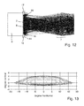
- the different beam paths of the light module 1 off FIG. 1 are in the FIGS. 8 . 10 and 12 shown.
- the corresponding light distributions on a screen are in the Figures 9 . 11 and 13 shown.
- the measuring screen is arranged at a defined distance from the light module 1.
- the optical axis of the light module 1 preferably passes through the center of the screen by the point HV at 0 ° horizontally and 0 ° vertically.
- FIG. 8 shows the beam path when only the LEDs of the light source 2 are activated, wherein FIG. 8 the special case is shown in which two centrally located LEDs of the light source 2 are deactivated.
- the two deactivated LEDs are in FIG. 8 designated by the reference numeral 19.
- the region of the resulting light distribution illuminated by the two deactivated LEDs 19 normally, that is to say in the activated state, is in FIG. 9 designated by the reference numeral 20.
- the two deactivated LEDs 19 of the light source 2 lead to a non-illuminated area 20 in the middle of the light distribution at about 0 ° horizontally with a width of about 2 ° horizontally.
- the non-illuminated area 20 in the center of the resulting light distribution thus extends in the horizontal direction, ie approximately from -1 ° to + 1 °.
- the height of the non-illuminated area 20 extends over the entire height of the resulting light distribution.
- the varying horizontal positions of the other road users can be taken into account by deliberately deactivating those LEDs 19 which are responsible for the generation of the light to be expelled Area 20 are responsible for the corresponding position.
- FIG. 10 the beam path of the light module 1 is shown, wherein only the light source 4 is activated to produce a part of the secondary light distribution.
- the secondary light distribution of the light source 4 is a side illumination right next to the main light distribution according to FIG. 9 ,
- the resulting light distribution of the side illumination on the right is in FIG. 11 shown.
- an activation of the other light source 3 would cause the generation of another part of the secondary light distribution in the form of a left side illumination. It is conceivable to activate both light sources 3, 4 at the same time.
- the shape and design, in particular the light intensity distribution, the resulting side illumination can be easily and effectively changed by changing the shape and / or orientation of the Concave mirror 18 and / or the deflection mirror 17 is changed. It is even conceivable to vary the shape and / or orientation of the concave mirror 18 and / or of the deflection mirror 17 during the operation of the light module 1 so as to be able to adaptively change the design and the shape of the resulting side illumination during the operation of the illumination device. As a result, it would be possible, for example, to react to current traffic or ambient conditions and to illuminate the lateral edge regions of the resulting overall light distribution more or less strongly depending on the situation.
- FIG. 12 is the beam path of the light module 1 of the invention FIG. 1 shown, with all the light sources 2, 3, 4 are activated, including the two in FIGS. 8 and 9 still deactivated LEDs 19 and the light source 3.
- the overall light distribution shown is, for example, a high beam (if the light distribution would be lowered so that the upper Patoscuro below the horizontal at about -1 ° would be vertical) a fog light or (with respect to a high beam intensity reduced) a daytime running light.
- FIG. 2 a further embodiment of the light module 1 according to the invention is shown.
- a light source 4 for generating a secondary light distribution and, correspondingly, only one primary optics 17, 18 associated with the light source 4 are provided.
- the secondary optics 7 is formed as a faceted paraboloid.
- the individual facets of the reflector 7 designed in this way preferably have different focal lengths and approximately identical cutting widths to the focal point 10 (cf. FIGS. 4b . 5b . 6b ) on.
- FIG. 3 shows a beam path in the light module 1 from FIG. 2 , in which FIG. 3a the vertical beam path and FIG. 3b shows the horizontal beam path.
- the concave mirror 18 increases in the vertical beam path the LED chip of the light source 4 with an edge length t at least to the height H of the mirror surface of the Umlenkkspeigels 17.
- the magnification M results approximately from the ratio of the distances S2 / S1.
- the concave mirror 18 concentrates in the horizontal beam path the light for the secondary light distribution on the deflection mirror 17 immediately adjacent to the adjacent primary optics array 8 for the main light distribution.
- On the mirror surface of the Umlenkkspeigels 17 results in an image of the light source 4.
- the deflecting mirror 17 directs the incident light to the secondary optics 7, which projects the light source image for generating the secondary light distribution on the road.
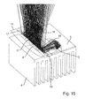
- FIG. 14 shows a further embodiment of a light module 1 according to the invention, wherein the representation of the secondary optics 7 has been omitted.
- the primary optics 8 for the main light distribution comprises an array of conical light guides whose light exit surfaces 21 from the LEDs of the light source 2 for the main light distribution (see FIG. FIG. 9 ) are illuminated evenly.
- the intermediate light distributions on the light exit surfaces 21 of the light guide array 8 and the light source images on the mirror surfaces of the deflection mirrors 15, 17 are approximately in the shell-shaped Petzval surface 14, the so-called Petzval shell, the secondary optics 7.
- the primary optics 8 comprises an array of conical reflectors which generate the intermediate light distributions (illuminated light exit surfaces 21) for the main light distribution.
- the light exit surfaces 21 of the reflector array 8 ie, the front openings of the individual reflectors located in the light exit direction
- the mirror surfaces of the deflection mirrors 15, 17 lie approximately in the Petzval shell 14 of the secondary optics 7.
- the primary optics 8 comprises an array of converging lenses which generate the intermediate light distributions for the main light distribution.
- the light exit surfaces 21 of the lens array 8 and the mirror surfaces of the deflection mirrors 15, 17 are approximately in a shell-shaped Petzval relations 14 of the secondary optics. 7
- Petzval surface 14 is an area whose points are imaged by the secondary optics 7 as equal as possible and in the desired manner to a far away in the direction of travel or emission direction image surface. These object points can be mapped as lines or rectangles or the like instead of points in the same way.
- infinitesimally small zones of the secondary optics 7 in a picture area located far in front of the light module 1 or the motor vehicle design predominantly the same sized and similarly oriented pictures of the intermediate light distributions located in the object-side Petzval area 14 of the secondary optics 7.
- the individual intermediate light distributions can be offset from one another in the angular space (for example, blurring of the light distribution in the vertical and / or horizontal direction), in particular in the vertical direction.
- the optical surfaces of the secondary optics 7 preferably have different refractive powers or curvatures in their vertical sections than in their horizontal sections.
- the dimensions of the deflection mirror 15; 17 are preferably selected such that the light source 3; 4 for the secondary light distribution through the concave mirror 16; 18 and the deflection mirror 15; 17 is increased at least to a light source image of the size of the light exit surface 21 of the adjacent primary optics 8. To compensate for manufacturing and assembly tolerances, it is advisable to choose the magnification even slightly larger.
- the primary optics 8 for the main light distribution have a height H and a square LED chip of the light source 3; 4 for the secondary light distribution has a side length t, the magnification of the concave mirror 16;
- M H / t or greater.
- the route S1 begins at the center of the light source 3; 4 for the secondary light distribution and propagates in the direction of the main emission of the light source 3; 4, with an LED especially perpendicular to the LED chip.
- the distance S1 ends with the impact on the reflection surface of the concave mirror 16; 18.
- the distance S2 begins and extends in the direction of the deflection mirror 15; 17, preferably on the center of the deflection mirror.
- the deflection mirror 15; 17 for the secondary light distribution or its mirror surface on the one hand and the primary optics array 8 for the main light distribution or its light exit surfaces 21 on the other hand as precisely and immediately next to each other to position, so that the intermediate light distributions and the light source images of main and secondary light distribution after the projection by the secondary optics connect as seamlessly as possible in the resulting total light distribution.
- This can be achieved, for example, by integrally forming both elements (deflecting mirrors 15, 17 and primary optics 8).
Landscapes
- Engineering & Computer Science (AREA)
- General Engineering & Computer Science (AREA)
- Physics & Mathematics (AREA)
- Microelectronics & Electronic Packaging (AREA)
- Optics & Photonics (AREA)
- Non-Portable Lighting Devices Or Systems Thereof (AREA)
- Lighting Device Outwards From Vehicle And Optical Signal (AREA)
Applications Claiming Priority (1)
| Application Number | Priority Date | Filing Date | Title |
|---|---|---|---|
| DE102013206489.6A DE102013206489A1 (de) | 2013-04-11 | 2013-04-11 | Lichtmodul einer Kraftfahrzeugbeleuchtungseinrichtung |
Publications (3)
| Publication Number | Publication Date |
|---|---|
| EP2789901A2 true EP2789901A2 (fr) | 2014-10-15 |
| EP2789901A3 EP2789901A3 (fr) | 2016-09-07 |
| EP2789901B1 EP2789901B1 (fr) | 2020-05-06 |
Family
ID=50289567
Family Applications (1)
| Application Number | Title | Priority Date | Filing Date |
|---|---|---|---|
| EP14160768.9A Not-in-force EP2789901B1 (fr) | 2013-04-11 | 2014-03-19 | Module d'éclairage pour un dispositif d'éclairage de véhicule automobile |
Country Status (4)
| Country | Link |
|---|---|
| US (1) | US9528672B2 (fr) |
| EP (1) | EP2789901B1 (fr) |
| CN (1) | CN104100903B (fr) |
| DE (1) | DE102013206489A1 (fr) |
Cited By (5)
| Publication number | Priority date | Publication date | Assignee | Title |
|---|---|---|---|---|
| CN105066041A (zh) * | 2015-08-14 | 2015-11-18 | 安徽江淮汽车股份有限公司 | 一种侧转向信号灯 |
| EP3159597A1 (fr) * | 2015-10-21 | 2017-04-26 | Stanley Electric Co., Ltd. | Lampe véhiculaire |
| DE102016013510A1 (de) | 2016-04-18 | 2017-10-19 | Kastriot Merlaku | Scheinwerfer-System für Fahrzeuge aller Art, mit mindestens einem Leuchtmittel und eine Kamera für die Fahrbahn-Erfassung |
| EP3351849A1 (fr) * | 2016-12-23 | 2018-07-25 | Automotive Lighting Reutlingen GmbH | Module à led et dispositif d'éclairage pour un véhicule automobile pourvu d'une pluralité de tels modules à led |
| EP4471328A1 (fr) * | 2023-05-30 | 2024-12-04 | Hella Autotechnik Nova, s.r.o. | Projecteur pour véhicule automobile et élément optique pour le projecteur |
Families Citing this family (13)
| Publication number | Priority date | Publication date | Assignee | Title |
|---|---|---|---|---|
| KR101529166B1 (ko) * | 2013-08-06 | 2015-06-16 | 현대모비스 주식회사 | 차량용 램프 |
| DE102014009592A1 (de) * | 2014-06-27 | 2015-12-31 | Audi Ag | Scheinwerfervorrichtung für ein Kraftfahrzeug, Kraftfahrzeug und Verfahren zum Betreiben einer Scheinwerfervorrichtung |
| EP3379139B1 (fr) * | 2015-11-20 | 2025-01-22 | Koito Manufacturing Co., Ltd. | Unité de luminaire |
| FR3051160B1 (fr) * | 2016-05-11 | 2018-05-25 | Peugeot Citroen Automobiles Sa | Systeme d'eclairage pour vehicule automobile |
| FR3056693B1 (fr) * | 2016-09-29 | 2020-06-19 | Valeo Vision | Dispositif d'eclairage en bandes pour projecteur de vehicule automobile |
| DE102017117392A1 (de) * | 2017-08-01 | 2019-02-07 | HELLA GmbH & Co. KGaA | Beleuchtungsvorrichtung für Fahrzeuge |
| JP6571734B2 (ja) * | 2017-09-04 | 2019-09-04 | トヨタ自動車株式会社 | 車両用照明装置 |
| JP6589955B2 (ja) * | 2017-09-22 | 2019-10-16 | 日亜化学工業株式会社 | 発光モジュール及び車載用灯具 |
| FR3074257B1 (fr) * | 2017-11-27 | 2020-11-13 | Valeo Vision | Module lumineux pour l’eclairage et/ou la signalisation d’un vehicule automobile |
| DE102018110793B4 (de) * | 2018-05-04 | 2026-02-05 | HELLA GmbH & Co. KGaA | Projektionsscheinwerfer |
| DE102019108233A1 (de) * | 2019-03-29 | 2020-10-01 | Automotive Lighting Reutlingen Gmbh | Lichtmodul für einen Kraftfahrzeugscheinwerfer mit n in einer Reihe nebeneinander angeordneten Teillichtmodulen |
| DE102020210548A1 (de) | 2020-08-20 | 2022-02-24 | Volkswagen Aktiengesellschaft | Fahrzeugscheinwerfer mit Kompensation von Inhomogenitäten in der Lichtverteilung |
| DE102023201959A1 (de) * | 2023-03-03 | 2024-09-05 | Volkswagen Aktiengesellschaft | Verfahren zur Erzeugung einer Lichtverteilung durch einen Scheinwerfer eines Kraftfahrzeugs sowie Scheinwerfer zur Durchführung des Verfahrens |
Citations (1)
| Publication number | Priority date | Publication date | Assignee | Title |
|---|---|---|---|---|
| US20060120094A1 (en) | 2004-12-07 | 2006-06-08 | Koito Manufacturing Co., Ltd. | Vehicular illumination lamp |
Family Cites Families (14)
| Publication number | Priority date | Publication date | Assignee | Title |
|---|---|---|---|---|
| JPH01232602A (ja) * | 1988-03-11 | 1989-09-18 | Koito Mfg Co Ltd | 自動車用前照灯 |
| JP4771055B2 (ja) * | 2005-06-16 | 2011-09-14 | スタンレー電気株式会社 | 車両用灯具及びそのled光源 |
| JP4529946B2 (ja) * | 2006-06-01 | 2010-08-25 | 市光工業株式会社 | 車両用灯具 |
| JP2008123753A (ja) * | 2006-11-09 | 2008-05-29 | Koito Mfg Co Ltd | 車両用灯具ユニット |
| JP2008153108A (ja) * | 2006-12-19 | 2008-07-03 | Ichikoh Ind Ltd | 車両用灯具 |
| FR2917811B1 (fr) * | 2007-06-25 | 2009-10-02 | Valeo Vision Sa | Module d'eclairage pour projecteur de vehicule automobile |
| JP5069985B2 (ja) * | 2007-09-13 | 2012-11-07 | 株式会社小糸製作所 | 車両用前照灯の灯具ユニットおよび車両用前照灯 |
| JP5407097B2 (ja) * | 2008-02-15 | 2014-02-05 | スタンレー電気株式会社 | 車両用灯具 |
| JP2009277482A (ja) * | 2008-05-14 | 2009-11-26 | Ichikoh Ind Ltd | 車両用灯具 |
| JP5388546B2 (ja) * | 2008-11-10 | 2014-01-15 | 株式会社小糸製作所 | 灯具ユニット |
| DE102009008631B4 (de) * | 2009-02-12 | 2016-11-03 | Automotive Lighting Reutlingen Gmbh | Projektionsmodul für einen Kraftfahrzeugscheinwerfer |
| DE102010041096B4 (de) * | 2010-09-21 | 2024-05-08 | Osram Gmbh | Leuchtvorrichtung |
| DE102011004569A1 (de) * | 2011-02-23 | 2012-08-23 | Automotive Lighting Reutlingen Gmbh | Zum Einbau in einem Kraftfahrzeug vorgesehene Beleuchtungseinrichtung |
| FR2984458B1 (fr) * | 2011-12-19 | 2018-03-09 | Valeo Vision | Module d'eclairage generateur d'un entrelacement de bandes lumineuses |
-
2013
- 2013-04-11 DE DE102013206489.6A patent/DE102013206489A1/de not_active Ceased
-
2014
- 2014-03-19 EP EP14160768.9A patent/EP2789901B1/fr not_active Not-in-force
- 2014-03-31 US US14/230,714 patent/US9528672B2/en not_active Expired - Fee Related
- 2014-04-03 CN CN201410133586.9A patent/CN104100903B/zh not_active Expired - Fee Related
Patent Citations (1)
| Publication number | Priority date | Publication date | Assignee | Title |
|---|---|---|---|---|
| US20060120094A1 (en) | 2004-12-07 | 2006-06-08 | Koito Manufacturing Co., Ltd. | Vehicular illumination lamp |
Cited By (10)
| Publication number | Priority date | Publication date | Assignee | Title |
|---|---|---|---|---|
| CN105066041A (zh) * | 2015-08-14 | 2015-11-18 | 安徽江淮汽车股份有限公司 | 一种侧转向信号灯 |
| EP3159597A1 (fr) * | 2015-10-21 | 2017-04-26 | Stanley Electric Co., Ltd. | Lampe véhiculaire |
| JP2017079173A (ja) * | 2015-10-21 | 2017-04-27 | スタンレー電気株式会社 | 車両用灯具 |
| US9903552B2 (en) | 2015-10-21 | 2018-02-27 | Stanley Electric Co., Ltd. | Vehicular lamp |
| DE102016013510A1 (de) | 2016-04-18 | 2017-10-19 | Kastriot Merlaku | Scheinwerfer-System für Fahrzeuge aller Art, mit mindestens einem Leuchtmittel und eine Kamera für die Fahrbahn-Erfassung |
| DE102016013510B4 (de) | 2016-04-18 | 2019-03-14 | Kastriot Merlaku | Scheinwerfer-System für Fahrzeuge aller Art, mit mindestens einem Leuchtmittel und eine Kamera für die Fahrbahn-Erfassung |
| EP3351849A1 (fr) * | 2016-12-23 | 2018-07-25 | Automotive Lighting Reutlingen GmbH | Module à led et dispositif d'éclairage pour un véhicule automobile pourvu d'une pluralité de tels modules à led |
| US10323816B2 (en) | 2016-12-23 | 2019-06-18 | Automotive Lighting Reutlingen Gmbh | LED module and lighting device for a motor vehicle with several such LED modules |
| EP4471328A1 (fr) * | 2023-05-30 | 2024-12-04 | Hella Autotechnik Nova, s.r.o. | Projecteur pour véhicule automobile et élément optique pour le projecteur |
| US12203623B2 (en) | 2023-05-30 | 2025-01-21 | Hella Autotechnik Nova S.R.O. | Headlight for an automobile and optical element for the headlight |
Also Published As
| Publication number | Publication date |
|---|---|
| DE102013206489A1 (de) | 2014-10-30 |
| US20140307458A1 (en) | 2014-10-16 |
| CN104100903B (zh) | 2018-08-28 |
| CN104100903A (zh) | 2014-10-15 |
| EP2789901A3 (fr) | 2016-09-07 |
| US9528672B2 (en) | 2016-12-27 |
| EP2789901B1 (fr) | 2020-05-06 |
Similar Documents
| Publication | Publication Date | Title |
|---|---|---|
| EP2789901B1 (fr) | Module d'éclairage pour un dispositif d'éclairage de véhicule automobile | |
| EP2910847B1 (fr) | Module d'éclairage d'un projecteur de véhicule automobile et projecteur avec un tel module d'éclairage | |
| EP2799761B1 (fr) | Module d'éclairage de phare de véhicule automobile | |
| EP2799762B1 (fr) | Module d'éclairage de phare de véhicule automobile | |
| EP3351849B1 (fr) | Module à led et dispositif d'éclairage pour un véhicule automobile pourvu d'une pluralité de tels modules à led | |
| EP2505910B1 (fr) | Phare de véhicule automobile équipé d'une source lumineuse semi-conductrice | |
| EP2719940B1 (fr) | Module d'éclairage | |
| DE102014200368B4 (de) | Teilfernlicht-Projektionslichtmodul für einen Kraftfahrzeugscheinwerfer | |
| DE102014205994B4 (de) | Lichtmodul mit Halbleiterlichtquelle und Vorsatzoptik und Kraftfahrzeugscheinwerfer mit einem solchen Lichtmodul | |
| EP3080513B1 (fr) | Dispositif d'éclairage de véhicule automobile | |
| DE202011103703U1 (de) | Lichtmodul eines Kraftfahrzeugs zur Erzeugung einer Sportverteilung einer Fernlicht-Lichtverteilung und Kraftfahrzeugscheinwerfer mit einem solchen Modul | |
| EP2834555B1 (fr) | Dispositif d'éclairage pour véhicule | |
| DE102013205487A1 (de) | Kraftfahrzeugleuchte für dynamische Leuchtenfunktionen | |
| WO2011154470A1 (fr) | Accessoire optique constitué d'un matériau transparent pour la focalisation de lumière, ensemble de lentilles comportant au moins un tel accessoire optique, et module de lumière doté d'un tel ensemble de lentilles | |
| WO2018045402A1 (fr) | Projecteur de véhicule | |
| EP2863108B1 (fr) | Module à LED d'un phare de véhicule automobile | |
| EP3301350B1 (fr) | Module d'éclairage pour phare de véhicule automobile | |
| EP2523022A1 (fr) | Module d'éclairage pour un phare de véhicule automobile destiné à la production d'une distribution lumineuse variable et phare de véhicule automobile doté d'un tel module d'éclairage | |
| DE102013215359B3 (de) | Mechanikfreies Kurvenlichtmodul | |
| DE102017115899A1 (de) | Kraftfahrzeugleuchte und Kraftfahrzeugscheinwerfer mit einer solchen Leuchte | |
| DE102014221389A1 (de) | Lichtmodul einer Beleuchtungseinrichtung und Beleuchtungseinrichtung mit einem solchen Lichtmodul | |
| EP2500630B1 (fr) | Optique transparente ou lentille d'un dispositif d'éclairage d'un véhicule automobile | |
| DE102015201856B4 (de) | Kfz-Scheinwerfer | |
| DE102012215124B4 (de) | Beleuchtungseinrichtung mit mehreren Lichtquellen und Lichtleitkörpern sowie einem Reflektor | |
| DE102014204613A1 (de) | Beleuchtungseinrichtung für ein Kraftfahrzeug |
Legal Events
| Date | Code | Title | Description |
|---|---|---|---|
| PUAI | Public reference made under article 153(3) epc to a published international application that has entered the european phase |
Free format text: ORIGINAL CODE: 0009012 |
|
| 17P | Request for examination filed |
Effective date: 20140319 |
|
| AK | Designated contracting states |
Kind code of ref document: A2 Designated state(s): AL AT BE BG CH CY CZ DE DK EE ES FI FR GB GR HR HU IE IS IT LI LT LU LV MC MK MT NL NO PL PT RO RS SE SI SK SM TR |
|
| AX | Request for extension of the european patent |
Extension state: BA ME |
|
| PUAL | Search report despatched |
Free format text: ORIGINAL CODE: 0009013 |
|
| RIC1 | Information provided on ipc code assigned before grant |
Ipc: F21S 8/10 20060101AFI20160728BHEP |
|
| AK | Designated contracting states |
Kind code of ref document: A3 Designated state(s): AL AT BE BG CH CY CZ DE DK EE ES FI FR GB GR HR HU IE IS IT LI LT LU LV MC MK MT NL NO PL PT RO RS SE SI SK SM TR |
|
| AX | Request for extension of the european patent |
Extension state: BA ME |
|
| STAA | Information on the status of an ep patent application or granted ep patent |
Free format text: STATUS: REQUEST FOR EXAMINATION WAS MADE |
|
| R17P | Request for examination filed (corrected) |
Effective date: 20170103 |
|
| RBV | Designated contracting states (corrected) |
Designated state(s): AL AT BE BG CH CY CZ DE DK EE ES FI FR GB GR HR HU IE IS IT LI LT LU LV MC MK MT NL NO PL PT RO RS SE SI SK SM TR |
|
| REG | Reference to a national code |
Ref country code: DE Ref legal event code: R079 Ref document number: 502014014115 Country of ref document: DE Free format text: PREVIOUS MAIN CLASS: F21S0008100000 Ipc: F21S0041143000 |
|
| RIC1 | Information provided on ipc code assigned before grant |
Ipc: F21S 41/33 20180101ALI20191010BHEP Ipc: F21S 41/24 20180101ALI20191010BHEP Ipc: F21S 41/32 20180101ALI20191010BHEP Ipc: F21S 41/147 20180101ALI20191010BHEP Ipc: F21S 41/143 20180101AFI20191010BHEP Ipc: F21S 41/663 20180101ALI20191010BHEP Ipc: F21S 41/36 20180101ALI20191010BHEP Ipc: F21S 41/43 20180101ALI20191010BHEP Ipc: F21S 41/29 20180101ALI20191010BHEP Ipc: F21S 41/20 20180101ALI20191010BHEP |
|
| GRAP | Despatch of communication of intention to grant a patent |
Free format text: ORIGINAL CODE: EPIDOSNIGR1 |
|
| STAA | Information on the status of an ep patent application or granted ep patent |
Free format text: STATUS: GRANT OF PATENT IS INTENDED |
|
| INTG | Intention to grant announced |
Effective date: 20191202 |
|
| GRAS | Grant fee paid |
Free format text: ORIGINAL CODE: EPIDOSNIGR3 |
|
| GRAA | (expected) grant |
Free format text: ORIGINAL CODE: 0009210 |
|
| STAA | Information on the status of an ep patent application or granted ep patent |
Free format text: STATUS: THE PATENT HAS BEEN GRANTED |
|
| AK | Designated contracting states |
Kind code of ref document: B1 Designated state(s): AL AT BE BG CH CY CZ DE DK EE ES FI FR GB GR HR HU IE IS IT LI LT LU LV MC MK MT NL NO PL PT RO RS SE SI SK SM TR |
|
| REG | Reference to a national code |
Ref country code: GB Ref legal event code: FG4D Free format text: NOT ENGLISH |
|
| REG | Reference to a national code |
Ref country code: CH Ref legal event code: EP Ref country code: AT Ref legal event code: REF Ref document number: 1267323 Country of ref document: AT Kind code of ref document: T Effective date: 20200515 |
|
| REG | Reference to a national code |
Ref country code: DE Ref legal event code: R096 Ref document number: 502014014115 Country of ref document: DE |
|
| REG | Reference to a national code |
Ref country code: IE Ref legal event code: FG4D Free format text: LANGUAGE OF EP DOCUMENT: GERMAN |
|
| REG | Reference to a national code |
Ref country code: LT Ref legal event code: MG4D |
|
| REG | Reference to a national code |
Ref country code: NL Ref legal event code: MP Effective date: 20200506 |
|
| PG25 | Lapsed in a contracting state [announced via postgrant information from national office to epo] |
Ref country code: LT Free format text: LAPSE BECAUSE OF FAILURE TO SUBMIT A TRANSLATION OF THE DESCRIPTION OR TO PAY THE FEE WITHIN THE PRESCRIBED TIME-LIMIT Effective date: 20200506 Ref country code: FI Free format text: LAPSE BECAUSE OF FAILURE TO SUBMIT A TRANSLATION OF THE DESCRIPTION OR TO PAY THE FEE WITHIN THE PRESCRIBED TIME-LIMIT Effective date: 20200506 Ref country code: SE Free format text: LAPSE BECAUSE OF FAILURE TO SUBMIT A TRANSLATION OF THE DESCRIPTION OR TO PAY THE FEE WITHIN THE PRESCRIBED TIME-LIMIT Effective date: 20200506 Ref country code: GR Free format text: LAPSE BECAUSE OF FAILURE TO SUBMIT A TRANSLATION OF THE DESCRIPTION OR TO PAY THE FEE WITHIN THE PRESCRIBED TIME-LIMIT Effective date: 20200807 Ref country code: IS Free format text: LAPSE BECAUSE OF FAILURE TO SUBMIT A TRANSLATION OF THE DESCRIPTION OR TO PAY THE FEE WITHIN THE PRESCRIBED TIME-LIMIT Effective date: 20200906 Ref country code: NO Free format text: LAPSE BECAUSE OF FAILURE TO SUBMIT A TRANSLATION OF THE DESCRIPTION OR TO PAY THE FEE WITHIN THE PRESCRIBED TIME-LIMIT Effective date: 20200806 Ref country code: PT Free format text: LAPSE BECAUSE OF FAILURE TO SUBMIT A TRANSLATION OF THE DESCRIPTION OR TO PAY THE FEE WITHIN THE PRESCRIBED TIME-LIMIT Effective date: 20200907 |
|
| PG25 | Lapsed in a contracting state [announced via postgrant information from national office to epo] |
Ref country code: RS Free format text: LAPSE BECAUSE OF FAILURE TO SUBMIT A TRANSLATION OF THE DESCRIPTION OR TO PAY THE FEE WITHIN THE PRESCRIBED TIME-LIMIT Effective date: 20200506 Ref country code: HR Free format text: LAPSE BECAUSE OF FAILURE TO SUBMIT A TRANSLATION OF THE DESCRIPTION OR TO PAY THE FEE WITHIN THE PRESCRIBED TIME-LIMIT Effective date: 20200506 Ref country code: LV Free format text: LAPSE BECAUSE OF FAILURE TO SUBMIT A TRANSLATION OF THE DESCRIPTION OR TO PAY THE FEE WITHIN THE PRESCRIBED TIME-LIMIT Effective date: 20200506 Ref country code: BG Free format text: LAPSE BECAUSE OF FAILURE TO SUBMIT A TRANSLATION OF THE DESCRIPTION OR TO PAY THE FEE WITHIN THE PRESCRIBED TIME-LIMIT Effective date: 20200806 |
|
| PG25 | Lapsed in a contracting state [announced via postgrant information from national office to epo] |
Ref country code: NL Free format text: LAPSE BECAUSE OF FAILURE TO SUBMIT A TRANSLATION OF THE DESCRIPTION OR TO PAY THE FEE WITHIN THE PRESCRIBED TIME-LIMIT Effective date: 20200506 Ref country code: AL Free format text: LAPSE BECAUSE OF FAILURE TO SUBMIT A TRANSLATION OF THE DESCRIPTION OR TO PAY THE FEE WITHIN THE PRESCRIBED TIME-LIMIT Effective date: 20200506 |
|
| PG25 | Lapsed in a contracting state [announced via postgrant information from national office to epo] |
Ref country code: IT Free format text: LAPSE BECAUSE OF FAILURE TO SUBMIT A TRANSLATION OF THE DESCRIPTION OR TO PAY THE FEE WITHIN THE PRESCRIBED TIME-LIMIT Effective date: 20200506 Ref country code: SM Free format text: LAPSE BECAUSE OF FAILURE TO SUBMIT A TRANSLATION OF THE DESCRIPTION OR TO PAY THE FEE WITHIN THE PRESCRIBED TIME-LIMIT Effective date: 20200506 Ref country code: EE Free format text: LAPSE BECAUSE OF FAILURE TO SUBMIT A TRANSLATION OF THE DESCRIPTION OR TO PAY THE FEE WITHIN THE PRESCRIBED TIME-LIMIT Effective date: 20200506 Ref country code: DK Free format text: LAPSE BECAUSE OF FAILURE TO SUBMIT A TRANSLATION OF THE DESCRIPTION OR TO PAY THE FEE WITHIN THE PRESCRIBED TIME-LIMIT Effective date: 20200506 Ref country code: RO Free format text: LAPSE BECAUSE OF FAILURE TO SUBMIT A TRANSLATION OF THE DESCRIPTION OR TO PAY THE FEE WITHIN THE PRESCRIBED TIME-LIMIT Effective date: 20200506 Ref country code: ES Free format text: LAPSE BECAUSE OF FAILURE TO SUBMIT A TRANSLATION OF THE DESCRIPTION OR TO PAY THE FEE WITHIN THE PRESCRIBED TIME-LIMIT Effective date: 20200506 Ref country code: CZ Free format text: LAPSE BECAUSE OF FAILURE TO SUBMIT A TRANSLATION OF THE DESCRIPTION OR TO PAY THE FEE WITHIN THE PRESCRIBED TIME-LIMIT Effective date: 20200506 |
|
| REG | Reference to a national code |
Ref country code: DE Ref legal event code: R097 Ref document number: 502014014115 Country of ref document: DE |
|
| PG25 | Lapsed in a contracting state [announced via postgrant information from national office to epo] |
Ref country code: PL Free format text: LAPSE BECAUSE OF FAILURE TO SUBMIT A TRANSLATION OF THE DESCRIPTION OR TO PAY THE FEE WITHIN THE PRESCRIBED TIME-LIMIT Effective date: 20200506 Ref country code: SK Free format text: LAPSE BECAUSE OF FAILURE TO SUBMIT A TRANSLATION OF THE DESCRIPTION OR TO PAY THE FEE WITHIN THE PRESCRIBED TIME-LIMIT Effective date: 20200506 |
|
| PLBE | No opposition filed within time limit |
Free format text: ORIGINAL CODE: 0009261 |
|
| STAA | Information on the status of an ep patent application or granted ep patent |
Free format text: STATUS: NO OPPOSITION FILED WITHIN TIME LIMIT |
|
| 26N | No opposition filed |
Effective date: 20210209 |
|
| PG25 | Lapsed in a contracting state [announced via postgrant information from national office to epo] |
Ref country code: SI Free format text: LAPSE BECAUSE OF FAILURE TO SUBMIT A TRANSLATION OF THE DESCRIPTION OR TO PAY THE FEE WITHIN THE PRESCRIBED TIME-LIMIT Effective date: 20200506 |
|
| PG25 | Lapsed in a contracting state [announced via postgrant information from national office to epo] |
Ref country code: MC Free format text: LAPSE BECAUSE OF FAILURE TO SUBMIT A TRANSLATION OF THE DESCRIPTION OR TO PAY THE FEE WITHIN THE PRESCRIBED TIME-LIMIT Effective date: 20200506 |
|
| REG | Reference to a national code |
Ref country code: CH Ref legal event code: PL |
|
| GBPC | Gb: european patent ceased through non-payment of renewal fee |
Effective date: 20210319 |
|
| REG | Reference to a national code |
Ref country code: BE Ref legal event code: MM Effective date: 20210331 |
|
| PG25 | Lapsed in a contracting state [announced via postgrant information from national office to epo] |
Ref country code: GB Free format text: LAPSE BECAUSE OF NON-PAYMENT OF DUE FEES Effective date: 20210319 Ref country code: IE Free format text: LAPSE BECAUSE OF NON-PAYMENT OF DUE FEES Effective date: 20210319 Ref country code: LU Free format text: LAPSE BECAUSE OF NON-PAYMENT OF DUE FEES Effective date: 20210319 Ref country code: LI Free format text: LAPSE BECAUSE OF NON-PAYMENT OF DUE FEES Effective date: 20210331 Ref country code: CH Free format text: LAPSE BECAUSE OF NON-PAYMENT OF DUE FEES Effective date: 20210331 |
|
| REG | Reference to a national code |
Ref country code: AT Ref legal event code: MM01 Ref document number: 1267323 Country of ref document: AT Kind code of ref document: T Effective date: 20210319 |
|
| PG25 | Lapsed in a contracting state [announced via postgrant information from national office to epo] |
Ref country code: BE Free format text: LAPSE BECAUSE OF NON-PAYMENT OF DUE FEES Effective date: 20210331 |
|
| PG25 | Lapsed in a contracting state [announced via postgrant information from national office to epo] |
Ref country code: AT Free format text: LAPSE BECAUSE OF NON-PAYMENT OF DUE FEES Effective date: 20210319 |
|
| PGFP | Annual fee paid to national office [announced via postgrant information from national office to epo] |
Ref country code: FR Payment date: 20230222 Year of fee payment: 10 |
|
| PG25 | Lapsed in a contracting state [announced via postgrant information from national office to epo] |
Ref country code: HU Free format text: LAPSE BECAUSE OF FAILURE TO SUBMIT A TRANSLATION OF THE DESCRIPTION OR TO PAY THE FEE WITHIN THE PRESCRIBED TIME-LIMIT; INVALID AB INITIO Effective date: 20140319 |
|
| PGFP | Annual fee paid to national office [announced via postgrant information from national office to epo] |
Ref country code: DE Payment date: 20230221 Year of fee payment: 10 |
|
| P01 | Opt-out of the competence of the unified patent court (upc) registered |
Effective date: 20230508 |
|
| PG25 | Lapsed in a contracting state [announced via postgrant information from national office to epo] |
Ref country code: CY Free format text: LAPSE BECAUSE OF FAILURE TO SUBMIT A TRANSLATION OF THE DESCRIPTION OR TO PAY THE FEE WITHIN THE PRESCRIBED TIME-LIMIT Effective date: 20200506 |
|
| PG25 | Lapsed in a contracting state [announced via postgrant information from national office to epo] |
Ref country code: MK Free format text: LAPSE BECAUSE OF FAILURE TO SUBMIT A TRANSLATION OF THE DESCRIPTION OR TO PAY THE FEE WITHIN THE PRESCRIBED TIME-LIMIT Effective date: 20200506 |
|
| PG25 | Lapsed in a contracting state [announced via postgrant information from national office to epo] |
Ref country code: MT Free format text: LAPSE BECAUSE OF FAILURE TO SUBMIT A TRANSLATION OF THE DESCRIPTION OR TO PAY THE FEE WITHIN THE PRESCRIBED TIME-LIMIT Effective date: 20200506 |
|
| REG | Reference to a national code |
Ref country code: DE Ref legal event code: R119 Ref document number: 502014014115 Country of ref document: DE |
|
| PG25 | Lapsed in a contracting state [announced via postgrant information from national office to epo] |
Ref country code: DE Free format text: LAPSE BECAUSE OF NON-PAYMENT OF DUE FEES Effective date: 20241001 |
|
| PG25 | Lapsed in a contracting state [announced via postgrant information from national office to epo] |
Ref country code: FR Free format text: LAPSE BECAUSE OF NON-PAYMENT OF DUE FEES Effective date: 20240331 |
|
| PG25 | Lapsed in a contracting state [announced via postgrant information from national office to epo] |
Ref country code: FR Free format text: LAPSE BECAUSE OF NON-PAYMENT OF DUE FEES Effective date: 20240331 Ref country code: DE Free format text: LAPSE BECAUSE OF NON-PAYMENT OF DUE FEES Effective date: 20241001 |
|
| PG25 | Lapsed in a contracting state [announced via postgrant information from national office to epo] |
Ref country code: TR Free format text: LAPSE BECAUSE OF FAILURE TO SUBMIT A TRANSLATION OF THE DESCRIPTION OR TO PAY THE FEE WITHIN THE PRESCRIBED TIME-LIMIT Effective date: 20200506 |