EP2910847B1 - Module d'éclairage d'un projecteur de véhicule automobile et projecteur avec un tel module d'éclairage - Google Patents
Module d'éclairage d'un projecteur de véhicule automobile et projecteur avec un tel module d'éclairage Download PDFInfo
- Publication number
- EP2910847B1 EP2910847B1 EP15150804.1A EP15150804A EP2910847B1 EP 2910847 B1 EP2910847 B1 EP 2910847B1 EP 15150804 A EP15150804 A EP 15150804A EP 2910847 B1 EP2910847 B1 EP 2910847B1
- Authority
- EP
- European Patent Office
- Prior art keywords
- light
- light module
- optics
- optic
- distributions
- Prior art date
- Legal status (The legal status is an assumption and is not a legal conclusion. Google has not performed a legal analysis and makes no representation as to the accuracy of the status listed.)
- Active
Links
Images




Classifications
-
- F—MECHANICAL ENGINEERING; LIGHTING; HEATING; WEAPONS; BLASTING
- F21—LIGHTING
- F21S—NON-PORTABLE LIGHTING DEVICES; SYSTEMS THEREOF; VEHICLE LIGHTING DEVICES SPECIALLY ADAPTED FOR VEHICLE EXTERIORS
- F21S41/00—Illuminating devices specially adapted for vehicle exteriors, e.g. headlamps
- F21S41/10—Illuminating devices specially adapted for vehicle exteriors, e.g. headlamps characterised by the light source
- F21S41/14—Illuminating devices specially adapted for vehicle exteriors, e.g. headlamps characterised by the light source characterised by the type of light source
- F21S41/141—Light emitting diodes [LED]
- F21S41/143—Light emitting diodes [LED] the main emission direction of the LED being parallel to the optical axis of the illuminating device
-
- F—MECHANICAL ENGINEERING; LIGHTING; HEATING; WEAPONS; BLASTING
- F21—LIGHTING
- F21S—NON-PORTABLE LIGHTING DEVICES; SYSTEMS THEREOF; VEHICLE LIGHTING DEVICES SPECIALLY ADAPTED FOR VEHICLE EXTERIORS
- F21S41/00—Illuminating devices specially adapted for vehicle exteriors, e.g. headlamps
- F21S41/20—Illuminating devices specially adapted for vehicle exteriors, e.g. headlamps characterised by refractors, transparent cover plates, light guides or filters
- F21S41/25—Projection lenses
- F21S41/255—Lenses with a front view of circular or truncated circular outline
-
- F—MECHANICAL ENGINEERING; LIGHTING; HEATING; WEAPONS; BLASTING
- F21—LIGHTING
- F21S—NON-PORTABLE LIGHTING DEVICES; SYSTEMS THEREOF; VEHICLE LIGHTING DEVICES SPECIALLY ADAPTED FOR VEHICLE EXTERIORS
- F21S41/00—Illuminating devices specially adapted for vehicle exteriors, e.g. headlamps
- F21S41/10—Illuminating devices specially adapted for vehicle exteriors, e.g. headlamps characterised by the light source
- F21S41/14—Illuminating devices specially adapted for vehicle exteriors, e.g. headlamps characterised by the light source characterised by the type of light source
- F21S41/141—Light emitting diodes [LED]
-
- F—MECHANICAL ENGINEERING; LIGHTING; HEATING; WEAPONS; BLASTING
- F21—LIGHTING
- F21S—NON-PORTABLE LIGHTING DEVICES; SYSTEMS THEREOF; VEHICLE LIGHTING DEVICES SPECIALLY ADAPTED FOR VEHICLE EXTERIORS
- F21S41/00—Illuminating devices specially adapted for vehicle exteriors, e.g. headlamps
- F21S41/10—Illuminating devices specially adapted for vehicle exteriors, e.g. headlamps characterised by the light source
- F21S41/14—Illuminating devices specially adapted for vehicle exteriors, e.g. headlamps characterised by the light source characterised by the type of light source
- F21S41/141—Light emitting diodes [LED]
- F21S41/147—Light emitting diodes [LED] the main emission direction of the LED being angled to the optical axis of the illuminating device
- F21S41/148—Light emitting diodes [LED] the main emission direction of the LED being angled to the optical axis of the illuminating device the main emission direction of the LED being perpendicular to the optical axis
-
- F—MECHANICAL ENGINEERING; LIGHTING; HEATING; WEAPONS; BLASTING
- F21—LIGHTING
- F21S—NON-PORTABLE LIGHTING DEVICES; SYSTEMS THEREOF; VEHICLE LIGHTING DEVICES SPECIALLY ADAPTED FOR VEHICLE EXTERIORS
- F21S41/00—Illuminating devices specially adapted for vehicle exteriors, e.g. headlamps
- F21S41/10—Illuminating devices specially adapted for vehicle exteriors, e.g. headlamps characterised by the light source
- F21S41/14—Illuminating devices specially adapted for vehicle exteriors, e.g. headlamps characterised by the light source characterised by the type of light source
- F21S41/141—Light emitting diodes [LED]
- F21S41/151—Light emitting diodes [LED] arranged in one or more lines
-
- F—MECHANICAL ENGINEERING; LIGHTING; HEATING; WEAPONS; BLASTING
- F21—LIGHTING
- F21S—NON-PORTABLE LIGHTING DEVICES; SYSTEMS THEREOF; VEHICLE LIGHTING DEVICES SPECIALLY ADAPTED FOR VEHICLE EXTERIORS
- F21S41/00—Illuminating devices specially adapted for vehicle exteriors, e.g. headlamps
- F21S41/20—Illuminating devices specially adapted for vehicle exteriors, e.g. headlamps characterised by refractors, transparent cover plates, light guides or filters
- F21S41/25—Projection lenses
- F21S41/26—Elongated lenses
-
- F—MECHANICAL ENGINEERING; LIGHTING; HEATING; WEAPONS; BLASTING
- F21—LIGHTING
- F21S—NON-PORTABLE LIGHTING DEVICES; SYSTEMS THEREOF; VEHICLE LIGHTING DEVICES SPECIALLY ADAPTED FOR VEHICLE EXTERIORS
- F21S41/00—Illuminating devices specially adapted for vehicle exteriors, e.g. headlamps
- F21S41/20—Illuminating devices specially adapted for vehicle exteriors, e.g. headlamps characterised by refractors, transparent cover plates, light guides or filters
- F21S41/29—Attachment thereof
- F21S41/295—Attachment thereof specially adapted to projection lenses
-
- F—MECHANICAL ENGINEERING; LIGHTING; HEATING; WEAPONS; BLASTING
- F21—LIGHTING
- F21S—NON-PORTABLE LIGHTING DEVICES; SYSTEMS THEREOF; VEHICLE LIGHTING DEVICES SPECIALLY ADAPTED FOR VEHICLE EXTERIORS
- F21S41/00—Illuminating devices specially adapted for vehicle exteriors, e.g. headlamps
- F21S41/30—Illuminating devices specially adapted for vehicle exteriors, e.g. headlamps characterised by reflectors
- F21S41/32—Optical layout thereof
-
- F—MECHANICAL ENGINEERING; LIGHTING; HEATING; WEAPONS; BLASTING
- F21—LIGHTING
- F21S—NON-PORTABLE LIGHTING DEVICES; SYSTEMS THEREOF; VEHICLE LIGHTING DEVICES SPECIALLY ADAPTED FOR VEHICLE EXTERIORS
- F21S41/00—Illuminating devices specially adapted for vehicle exteriors, e.g. headlamps
- F21S41/30—Illuminating devices specially adapted for vehicle exteriors, e.g. headlamps characterised by reflectors
- F21S41/32—Optical layout thereof
- F21S41/33—Multi-surface reflectors, e.g. reflectors with facets or reflectors with portions of different curvature
- F21S41/334—Multi-surface reflectors, e.g. reflectors with facets or reflectors with portions of different curvature the reflector consisting of patch like sectors
-
- F—MECHANICAL ENGINEERING; LIGHTING; HEATING; WEAPONS; BLASTING
- F21—LIGHTING
- F21S—NON-PORTABLE LIGHTING DEVICES; SYSTEMS THEREOF; VEHICLE LIGHTING DEVICES SPECIALLY ADAPTED FOR VEHICLE EXTERIORS
- F21S41/00—Illuminating devices specially adapted for vehicle exteriors, e.g. headlamps
- F21S41/30—Illuminating devices specially adapted for vehicle exteriors, e.g. headlamps characterised by reflectors
- F21S41/32—Optical layout thereof
- F21S41/36—Combinations of two or more separate reflectors
- F21S41/365—Combinations of two or more separate reflectors successively reflecting the light
-
- F—MECHANICAL ENGINEERING; LIGHTING; HEATING; WEAPONS; BLASTING
- F21—LIGHTING
- F21S—NON-PORTABLE LIGHTING DEVICES; SYSTEMS THEREOF; VEHICLE LIGHTING DEVICES SPECIALLY ADAPTED FOR VEHICLE EXTERIORS
- F21S41/00—Illuminating devices specially adapted for vehicle exteriors, e.g. headlamps
- F21S41/60—Illuminating devices specially adapted for vehicle exteriors, e.g. headlamps characterised by a variable light distribution
- F21S41/65—Illuminating devices specially adapted for vehicle exteriors, e.g. headlamps characterised by a variable light distribution by acting on light sources
- F21S41/663—Illuminating devices specially adapted for vehicle exteriors, e.g. headlamps characterised by a variable light distribution by acting on light sources by switching light sources
-
- F—MECHANICAL ENGINEERING; LIGHTING; HEATING; WEAPONS; BLASTING
- F21—LIGHTING
- F21S—NON-PORTABLE LIGHTING DEVICES; SYSTEMS THEREOF; VEHICLE LIGHTING DEVICES SPECIALLY ADAPTED FOR VEHICLE EXTERIORS
- F21S45/00—Arrangements within vehicle lighting devices specially adapted for vehicle exteriors, for purposes other than emission or distribution of light
- F21S45/40—Cooling of lighting devices
- F21S45/47—Passive cooling, e.g. using fins, thermal conductive elements or openings
- F21S45/48—Passive cooling, e.g. using fins, thermal conductive elements or openings with means for conducting heat from the inside to the outside of the lighting devices, e.g. with fins on the outer surface of the lighting device
-
- F—MECHANICAL ENGINEERING; LIGHTING; HEATING; WEAPONS; BLASTING
- F21—LIGHTING
- F21W—INDEXING SCHEME ASSOCIATED WITH SUBCLASSES F21K, F21L, F21S and F21V, RELATING TO USES OR APPLICATIONS OF LIGHTING DEVICES OR SYSTEMS
- F21W2102/00—Exterior vehicle lighting devices for illuminating purposes
-
- F—MECHANICAL ENGINEERING; LIGHTING; HEATING; WEAPONS; BLASTING
- F21—LIGHTING
- F21W—INDEXING SCHEME ASSOCIATED WITH SUBCLASSES F21K, F21L, F21S and F21V, RELATING TO USES OR APPLICATIONS OF LIGHTING DEVICES OR SYSTEMS
- F21W2102/00—Exterior vehicle lighting devices for illuminating purposes
- F21W2102/10—Arrangement or contour of the emitted light
- F21W2102/13—Arrangement or contour of the emitted light for high-beam region or low-beam region
- F21W2102/135—Arrangement or contour of the emitted light for high-beam region or low-beam region the light having cut-off lines, i.e. clear borderlines between emitted regions and dark regions
- F21W2102/14—Arrangement or contour of the emitted light for high-beam region or low-beam region the light having cut-off lines, i.e. clear borderlines between emitted regions and dark regions having vertical cut-off lines; specially adapted for adaptive high beams, i.e. wherein the beam is broader but avoids glaring other road users
-
- F—MECHANICAL ENGINEERING; LIGHTING; HEATING; WEAPONS; BLASTING
- F21—LIGHTING
- F21W—INDEXING SCHEME ASSOCIATED WITH SUBCLASSES F21K, F21L, F21S and F21V, RELATING TO USES OR APPLICATIONS OF LIGHTING DEVICES OR SYSTEMS
- F21W2102/00—Exterior vehicle lighting devices for illuminating purposes
- F21W2102/20—Illuminance distribution within the emitted light
-
- F—MECHANICAL ENGINEERING; LIGHTING; HEATING; WEAPONS; BLASTING
- F21—LIGHTING
- F21W—INDEXING SCHEME ASSOCIATED WITH SUBCLASSES F21K, F21L, F21S and F21V, RELATING TO USES OR APPLICATIONS OF LIGHTING DEVICES OR SYSTEMS
- F21W2107/00—Use or application of lighting devices on or in particular types of vehicles
- F21W2107/10—Use or application of lighting devices on or in particular types of vehicles for land vehicles
-
- F—MECHANICAL ENGINEERING; LIGHTING; HEATING; WEAPONS; BLASTING
- F21—LIGHTING
- F21Y—INDEXING SCHEME ASSOCIATED WITH SUBCLASSES F21K, F21L, F21S and F21V, RELATING TO THE FORM OR THE KIND OF THE LIGHT SOURCES OR OF THE COLOUR OF THE LIGHT EMITTED
- F21Y2115/00—Light-generating elements of semiconductor light sources
- F21Y2115/10—Light-emitting diodes [LED]
Definitions
- the present invention relates to a light module of a headlight of a motor vehicle with the features of the preamble of claim 1.
- a light module is known from DE 10 2011 077 636 A1 known.
- the invention further relates to a headlight for a motor vehicle.
- the headlight comprises a housing with a light exit opening closed by a transparent cover plate and at least one light module arranged in the housing and having the above-mentioned features.
- the light module described has a plurality of semiconductor light sources arranged next to one another for emitting light.
- a semiconductor light source is, for example, in the form of a light-emitting diode (for example an LED chip) with an essentially square or rectangular light-emitting surface.
- Each of the semiconductor light sources is assigned primary optics designed as a converging lens, which bundles the light emitted by the semiconductor light source assigned to it.
- Several converging lenses are arranged next to one another in accordance with the arrangement of the semiconductor light sources and combined to form a primary optics array.
- the converging lenses exist preferably made of a solid transparent material, for example glass or plastic.
- each collecting optic produces an essentially square or rectangular primary light distribution on its light exit surface, corresponding to the shape of the light-emitting surface of the associated light-emitting diode.
- the light module described further comprises a common secondary optics designed as a projection lens for all primary optics.
- the projection lens is focused on the light exit surfaces of the primary optics, so that it maps the primary light distributions as corresponding secondary light distributions on the road ahead of the motor vehicle.
- the totality of all secondary light distributions corresponds to the resulting total light distribution generated by the light module, which is, for example, a high beam distribution.
- the projection lens depicts the primary light distributions as stripe-shaped secondary light distributions with a significantly larger vertical than horizontal extension. It is conceivable that the individual stripe-shaped secondary light distributions are laterally limited by sharp vertical Patoscuro boundaries.
- the secondary optics can also be constructed in several parts, for example as a two-lens achromatic lens.
- a so-called glare-free high beam or partial high beam can be generated.
- the individual semiconductor light source (s) are deactivated as a function of a signal from detection means which are provided in the motor vehicle for detecting other road users in front of the motor vehicle.
- the detection means can comprise at least one camera, at least one ultrasonic sensor and / or at least one radar sensor.
- the secondary optics can be designed in such a way that the secondary light distributions imaged by them on the roadway in front of the motor vehicle directly adjoin one another without overlapping the secondary light distributions. If one of the semiconductor light sources is deactivated, the area of the corresponding secondary light distribution not present in the resulting light distribution of the light module is limited by relatively sharp vertical Patoscuro limits of the illuminated secondary light distributions of the activated adjacent semiconductor light sources. This large gradient of the illuminance can be perceived by a driver of the motor vehicle as subjectively disturbing.
- the secondary optics are designed in such a way that the secondary light distributions mapped by them on the roadway in front of the motor vehicle are arranged next to one another, at least lateral regions of mutually adjacent secondary light distributions overlapping one another.
- This can be achieved by modulating a basic shape of a light exit surface of the projection optics in such a way that a single primary light distribution is converted into a plurality of corresponding partial areas of the corresponding secondary light distribution, the partial areas being of the same size and with the same orientation relative in the horizontal direction shifted to each other and arranged to overlap each other.
- the entirety of all sub-areas resulting from a certain primary light distribution forms the corresponding secondary light distribution. In this way, sharp vertical Patoscuro boundaries, which limit the stripe-shaped secondary light distributions, and thus large gradients of the illuminance are avoided when the semiconductor light source is switched off.
- Lenticular arrays are best suited as primary optics because they only place low demands on materials, molded part and positioning accuracy. Comparatively small secondary optics are sufficient when using convergent lens arrays. The aberrations of the secondary optics can thus be kept small. A prerequisite for this, however, is a relatively large f-number (ratio of the focal length to the diameter of the effective entry surface of the secondary optics). In the case of lens systems, the aberrations are primarily color errors, while in the case of reflection systems with small f-numbers, they are primarily coma.
- a disadvantage of the primary optics designed as a converging lens array is that an opening angle of the emitted light beam with respect to an optical axis of the secondary optics is approximately the same size in all directions, that is to say it can be varied only slightly.
- an enlargement of the light-emitting area of the semiconductor light sources in a lens that is arranged close to the light source is similar in the horizontal and vertical directions.
- Anamorphic enlargement of the primary light distributions is only possible within very narrow limits.
- the vertical extent of strip-shaped matrix light distributions is a multiple of their width, it would be desirable to increase the light-emitting areas of the semiconductor light sources to the strip-shaped secondary ones Adapt light distributions, i.e. to enlarge the illuminated areas on the light exit surfaces of the primary optics more vertically than horizontally.
- the present invention is therefore based on the object of realizing a light module for generating at least two strip-shaped secondary light distributions which are directly adjacent or overlapping in at least one line, in which the at least two adjacent secondary light distributions from a plurality of semiconductor light sources or light source groups be formed, and in which the height of the secondary optics can be reduced without significant loss of luminous flux.
- the light module should have a shorter overall length than known light modules.
- a cylinder optic in the sense of the present invention is an optic that has no refractive power in the horizontal sections or at most a very low refractive power, in which the horizontal section curves are at least approximately straight lines, and that has a collecting effect in the vertical sections, i.e. a converging lens profile or has a concave mirror profile.
- the vertical intersection curves do not necessarily have to be circular. Furthermore, the centers of curvature in the vertical section do not have to coincide in a cylinder axis.
- the cylinder optics can significantly reduce the opening angle of the light beams from the primary optics in vertical section, so that the overall height of the secondary optics can also be reduced to a corresponding extent.
- the secondary optics focus on the light exit surfaces of the primary optics array via the cylinder optics.
- the cylindrical optics cause an anamorphic enlargement of the primary light distributions on the light exit surfaces of the primary optics, so that secondary light distributions (so-called pixels) arise, the height of which can be a multiple of the respective pixel width.
- the height of the secondary optics can be reduced to approximately the same extent. This is particularly suitable for common light module and headlight designs, which often require particularly flat and wide lenses and / or reflectors as secondary optics. This includes a result of the increasingly streamlined vehicle fronts in order to achieve fuel savings and low wind noise.
- the cylinder optics it is conceivable for the cylinder optics to have circular intersection curves in a vertical section and the centers of curvature in the vertical section to coincide in a cylinder axis. This describes the special case of a "real" cylinder lens or a “real” cylinder reflector with constant curvature over the entire surface and a common cylinder axis.
- a cylindrical concave mirror is used as the cylinder optics, the beam path can be folded simultaneously with this mirror, for example by folding the optical axis in a horizontal and / or vertical plane. In this way, the overall length of the optics can be significantly reduced.
- a cylinder optic designed as a cylinder reflector can have an at least partially parabolic profile.
- FIG 8 is an example of a motor vehicle headlight according to the invention in its entirety with the reference numeral 1.
- the headlight 1 comprises a housing 2, which is preferably made of a plastic material.
- a light exit opening 4 provided in the housing 2 in the light exit direction 3 is closed by means of a transparent cover plate 5.
- the cover plate 5 is made, for example, of glass or plastic.
- the cover plate 5 can be designed without optically effective profiles (for example prisms or cylindrical lenses) (so-called clear plate) or at least in some areas can be provided with optically active profiles which can cause a scattering of the light passing through, in particular in the horizontal direction (so-called. Lens).
- a lamp module 6 can be arranged in the interior of the headlight 1, which module is used to implement a lamp function (for example flashing light, daytime running light, position or position light, etc.).
- an inventive Light module 7 arranged, which is designed to realize a high beam distribution by superimposing a plurality of strip-shaped secondary light distributions each with an essentially vertical longitudinal extension (hereinafter also referred to as strip high beam).
- strip high beam By deliberately dimming or switching off individual strip-shaped secondary light distributions, areas of the high beam distribution can be hidden in which other road users have been detected in order to prevent their glare (so-called glare-free high beam or partial high beam).
- the high beam generated by the light module 7 can be one of several light distributions that can be generated by the light module 7.
- the high beam distribution generated by the light module 7 is only part of a light distribution that meets the legal requirements, another part of the light distribution that meets the legal requirements being generated by at least one other light module, for example the light module 8, of the headlight 1 can be.
- the light distribution generated by the light module 7 is a high-beam spot, while the light module 8 generates a high-beam basic distribution.
- a superposition of the two high beam partial light distributions (spot and basic light) creates a high beam that fulfills the legal requirements and / or ensures particularly efficient illumination of the road ahead of the vehicle.
- the light distribution generated by the light module 7 already meets the legal requirements for a high beam, but subjectively and / or objectively better illumination with high beam can be achieved by the superimposition with the partial light distribution generated by the light module 8.
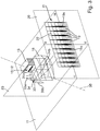
- FIG Figure 1a A first example of a light module 7 according to the invention is shown in FIG Figure 1a shown.
- the light module 7 comprises a plurality in a horizontal central plane 11 or parallel to it in a matrix-like manner juxtaposed, individually controllable semiconductor light sources 10 (cf. Figure 1b ) for emitting light.
- the light sources 10 are designed, for example, as light-emitting diodes (LEDs or LED chips).
- LEDs or LED chips light-emitting diodes
- “Matrix-like” in the sense of the present invention means that a plurality of LEDs 10 can be arranged next to one another in only one row and also next to and above one another in several rows.
- the light sources 10 are preferably attached to a heat sink 13 (directly or indirectly via a printed circuit board 14) in such a way that waste heat occurring during the operation of the light sources 10 can be effectively dissipated and released to the environment.
- the light module 7 comprises a plurality of primary optics 12, which are assigned to the semiconductor light sources 10 and likewise arranged next to one another in a matrix, for bundling at least some of the light emitted by the semiconductor light sources 10 and for generating a primary light distribution 15 (cf. Figure 7a ) in each case on light exit surfaces 16 of the primary optics 12.
- the primary optics 12 are preferably designed as converging lenses, so that the entirety of the primary optics 12 forms a converging lens array.
- the primary light distributions 15 correspond to a uniform illumination of the light exit surfaces 16 by the light in each case one of the light-emitting surfaces 17 of a light source 10.
- the light module 7 comprises common secondary optics, which in the exemplary embodiment shown is designed as a projection lens 18.
- the primary light distributions 15, which are shown on the light exit surfaces 16 of the primary optics 12 are imaged as strip-shaped secondary light distributions 19 on a roadway in front of the motor vehicle.
- the secondary light distributions 19 together result in an illuminated far range.
- the light module 7 thus serves Generation of a high beam distribution 21.
- the secondary light distributions 19 are not depicted on the roadway, but rather on a vertically oriented measuring screen 20 arranged at a distance from the light module 7.
- each of the secondary light distributions 19 encompasses the entire vertical extent shown.
- the resulting high-beam light distribution 21 is composed of a plurality of vertically aligned, strip-shaped (with essentially vertical longitudinal extension) secondary light distributions 19 arranged next to one another. In the example shown, ten secondary light distributions 19 are arranged next to one another.
- the lines 22 shown within the light distributions 19 are areas of the same illuminance (so-called isolux lines).
- the secondary light distributions 19 preferably each have their greatest illuminance values in the area of the horizontal plane 11.
- the illuminance values drop upward or downward within a strip-shaped secondary light distribution 19.
- a horizontal line HH is drawn on the measuring screen 20, which corresponds to a line of intersection of the horizontal plane 11 with the measuring screen 20.
- a vertical line VV is drawn on the measuring screen 20, which corresponds to a line of intersection of a vertical central plane 23 with the measuring screen 20.
- a line of intersection of the horizontal plane 11 and the vertical plane 23 corresponds to an optical axis 24 of the secondary optics 18 or in this case the entire light module 7. It can be clearly seen that a large part of the resulting light distribution 21 lies above the horizontal HH, that is to say a Long-distance area in front of the motor vehicle illuminated.
- Each secondary light distribution 19 is generated by the light from one of the semiconductor light sources 10 after it has been bundled by the corresponding primary optics 12 and imaged on the measuring screen 20 by the secondary optics 18.
- individual secondary light distributions 19 can be removed from the resulting high beam distribution 21 in a targeted manner.
- such light sources 10 can be deactivated in whose corresponding secondary light distribution 19 another road user (e.g. vehicle driving ahead or oncoming) has been detected. In this way, optimal illumination of the road area in front of the motor vehicle (usually with high beam) is achieved and at the same time it is ensured that the detected other road users are not dazzled.
- the secondary optics 18 can be designed in such a way that the secondary light distributions 19 which are imaged by them on the roadway (or the measuring screen 20) in front of the motor vehicle directly adjoin one another without overlap. If one of the semiconductor light sources 10 is deactivated, the area of the corresponding secondary light distribution 19 which is not present in the resulting light distribution 21 of the light module is limited by relatively sharp vertical light-dark limits 19a of the illuminated secondary light distributions 19 of the activated adjacent semiconductor light sources 10. This large gradient of the illuminance can be perceived by a driver of the motor vehicle as subjectively disturbing.
- the secondary optics 18 can be designed in such a way that the secondary light distributions 19 that they depict on the roadway (or the measuring screen 20) in front of the motor vehicle are arranged next to one another, at least lateral regions of mutually adjacent secondary light distributions 19 overlapping one another.
- a basic shape of a light exit surface 18a of the projection optics 18 is modulated such that a single primary light distribution 15 on a light exit surface 16 of a primary optics 12 is converted into a plurality of corresponding partial areas of the corresponding secondary light distribution 19.
- the partial areas are preferably of the same size and with the same orientation in the horizontal direction, displaced relative to one another and arranged to overlap one another.
- a cylinder optic 30 be arranged in the beam path of the light module 7 between the primary optics 12 and the secondary optics 18.
- a cylinder optic in the sense of the present invention is an optic that has no refractive power in the horizontal sections or at most a very low refractive power, in which the horizontal cutting curves are at least approximately straight lines, and that has a collecting effect in the vertical sections, i.e. a converging lens profile or has a concave mirror profile.
- the vertical intersection curves do not necessarily have to be circular. Furthermore, the centers of curvature in the vertical section do not have to coincide in a cylinder axis.
- the cylinder optics is designed as a cylinder lens 30 with a cylinder axis 31 which is oriented essentially horizontally, ie parallel to the horizontal plane 11 runs.
- the cylinder axis 31 can run on or through the light exit surfaces 16 of the primary optics 12.
- the cylinder axis 31 preferably extends in the horizontal plane 11 transversely to the optical axis 24 of the secondary optics 18.
- the secondary optics 18 together with the cylinder optics 30 form an optics system that focuses on the light exit surfaces 16 of the primary optics 12.
- the cylindrical lens 30 reduces the radiation angle of the primary optics 12 in the vertical direction.
- the height of the projection lens 18 can thereby be significantly reduced.
- a beam path 32 'without the use of the cylindrical lens 30 with the associated large projection lens 18' is shown in FIG Figure 1a shown in dashed lines.
- a beam path 32 of the light module 7 according to the invention with the cylindrical lens 30 is drawn in with a solid line. It can be clearly seen that the required overall height of the projection lens 18 in the present invention is significantly lower than in the case of the projection lens 18 'from the prior art.
- the cylinder optics In all horizontal sections (perpendicular to the vertical Patoscuro boundaries 19a of the secondary light distributions 19 or the stripe matrix), the cylinder optics have no or at most a very low refractive power. In these sections, the cylindrical lens 30 shows the same wall thickness. In contrast, in the vertical sections the refractive power of the cylinder optics is at a maximum. Here, the cylindrical lens 30 has the greatest wall thickness differences between the center of the lens and the edge of the lens.
- the cylinder optics (cylinder lens 30 or cylinder reflector 33) preferably generates the entire vertical course of the light distribution 21.
- the secondary optics 18, 36 preferably have no refractive power in the vertical sections, ie the secondary optics 18 is also a cylindrical lens educated. This applies to the special case of two crossed cylinder optics, the focal lines of which intersect in the middle of the light exit surfaces 16 of the primary optics 12.
- the cylindrical lens 30 preferably fulfills the sine condition, according to which the same imaging scales prevail in all lens zones.
- a vertical focal line of the cylindrical lens lies as centrally as possible on the light exit surfaces 16 of the primary optics 12.
- a cylindrical basic shape of the cylindrical lens 30 is superimposed on its light exit surface, which gives the lens sharp imaging properties, a modulation.
- This modulation is functionally defined in such a way that the cylindrical lens 30 has at least one optical surface, which modulates the basic shape in such a way that the cylindrical lens 30 converts an individual light distribution of the primary light distribution 15 into a plurality of second partial areas of an image 38 of the primary light distribution 15, which are the same are large and with the same orientation offset from each other overlapping.
- the modulation in the described configuration of the cylindrical lens 30 is generated by a first wave-shaped deformation of the optical surface which is superimposed on the basic shape and which comprises at least one concave and one convex half-wave.
- the wave-shaped deformation has a partially cylindrical shape, the cylinder axis of which is aligned parallel to the light-dark boundary of the light distribution.
- the wave-shaped deformation of the light exit surface of the cylindrical lens 30 is a component of the last optical surface in a beam path converting the primary light distribution 15 into the image 38.
- Figure 9 shows an example of a section of an equivalent light source arrangement for use in a light module 7 according to the invention. It is one of several Semiconductor light sources 10 shown in the form of an LED chip 17. One of several converging lenses 12 of a converging lens array is shown by way of example in the light exit direction after the LED chip 17. A division of the lens array is denoted by T. The division T corresponds to the width of the individual converging lenses 12 and the distance between the centers of adjacent LED chips 17. B LED denotes an edge length of the LED chip 17. A virtual LED chip is designated 17 '. The edge length of the virtual LED chip 17 'is denoted by B' LED .
- An object-side focal point of the converging lens 12 is denoted by F and a main point of the lens 12 is denoted by H.
- the main point H of a lens is defined as the point of intersection of a main plane of the lens with the optical axis of the lens.
- the secondary optics 18, 36 of the light module 7 according to the invention is preferably focused on a main point H of one of the converging lenses 12, preferably on the main point H of the converging lens 12 located near an optical axis 24 of the light module 7. If the light module 7 has a kinked optical axis (cf. e.g. Fig.
- the secondary optics 18, 36 of the light module 7 is preferably focused on a main point H of the converging lens 12 located near an optical partial axis 24b of the secondary optics 18, 36.
- the reference symbol f denotes the focal length of the lens 12 and S F an intersection of the lens 12.
- a distance between the LED chip 17 and the light entry surface of the converging lens 12 is S 1 and a distance between the virtual chip image 17 'and the light entry surface the lens 12 with S 2 .
- the LED chip 17 lies between the primary optics designed as a lens 12 in this example and their focal point F on the object side.
- the LED chip 17 is enlarged by the lens 12 in such a way that the (upright) virtual image 17 'of the chip 17 (in the light exit direction before the object-side lens focal point F) is approximately the same size as the lens 12, ie B ' LED ⁇ T.
- the following relationships apply approximately to the specified sizes: S F - S 1 S F ⁇ B LED T ⁇ B LED B ′ LED 0.1 mm ⁇ S 1 ⁇ 2 mm 1 x B LED ⁇ T ⁇ 4 x B LED
- the converging lenses 12 of the lens array do not serve to generate real intermediate images of the light sources 10 or the light-emitting surface 17, but merely form an illuminated surface (the primary light distribution 15) on the light exit surface 16 of the converging lenses 12.
- the light sources 10 are in this way between the light entry surfaces of the lenses 12 and the object-side focal points F of the lenses 12 are arranged such that the edges of the LED chip surfaces 17 lie on geometric connections from the focal points F to the lens edges.
- the radiation surfaces 17 of the light sources 10 are arranged perpendicular to the optical axes of the lenses 12. This results in a very uniform illumination of the lenses 12 and on the light exit surfaces 16 of the lenses 12 a particularly homogeneous light distribution, the so-called intermediate light distribution or primary light distribution 15.
- These primary light distributions 15 are generated by the secondary optics arrangement 18, 36 to produce the resulting total light distribution 21 of the Light module 7 shown on the road in front of the vehicle.
- the optical axes of the individual lenses 12 of the lens array all run in one plane; they are preferably parallel to one another. If the light module 7 has no kinked optical axis 24 (see, for example, Fig. 1a , 4th ), the optical axis of the secondary optics 18, 36 on the side facing the primary optics 12 is parallel to the optical axis of at least one of the lenses 18.
- FIG 2 a second embodiment of the present invention is shown.
- the cylinder optics in the beam path between the primary optics 12 and the secondary optics 18 are designed as a cylinder reflector 33. If it has a cylinder axis 35, it is preferably oriented essentially horizontally, ie it runs parallel to the horizontal plane 11.
- the cylinder axis 35 can run on or through the light exit surfaces 16 of the primary optics 12.
- the reflector 33 folds the beam path (folded beam path 34) in the vertical central plane 23.
- the overall length of the light module 7 can be significantly shortened by folding the beam path.
- the beam path 33 is thus folded by the cylinder reflector 33, ie the optical axis 24 of the light module 7 is angled, so that two partial axes 24a, 24b extending at an angle to one another result. This is preferably done in the vertical plane 23 (cf. Figures 2 and 5 ) or in a horizontal plane 11 (cf. Figure 3 ), which contains the bent optical axis 24a, 24b.
- a first optical axis 24a is preferably associated with one of the primary optics 12 and a further optical axis 24b with the secondary optics 18.
- the beam path is preferably folded by the cylinder reflector 33 at a right or acute angle.
- the cylindrical optics have no or at most a very low refractive power in all horizontal sections (perpendicular to the vertical Patoscuro boundaries 19a of the secondary light distributions 19 or the stripe matrix). In these sections, the curvature of a cylinder reflector 33 is zero. In contrast, in the vertical sections the refractive power of the cylinder optics is at a maximum.
- the cylinder reflector 33 or its reflection surface shows maximum curvatures in the vertical sections.
- the cylindrical reflector 33 can have an at least partially parabolic profile. A horizontal focal line of the cylinder reflector 33 lies as centrally as possible on the light exit surfaces 16 of the primary optics 12.
- FIG. 3 A further exemplary embodiment is shown in which the beam path is folded in a horizontal plane 11 (folded beam path 34).
- the cylinder optics is designed as a cylinder reflector 33. If the cylinder optics 33 has a cylinder axis 35, this is preferably aligned transversely to an bisector of an angle which is spanned by an optical axis 24a assigned to one of the primary optics 12 and an optical axis 24b assigned to the secondary optics 18.
- the curvature in the vertical sections of the cylindrical deflecting mirror 33 is preferably varied such that the curvature (1 / radius) is larger on a mirror side 33a facing the primary optics 12 than on a side 33b facing the secondary optics 18 (cf.
- the reflection surface of the cylinder reflector 33 is also intended to be designed as a control surface, so that the curvature in the horizontal sections, for example in the horizontal plane 11, is still zero.
- the cylindrical surface thus becomes a conical surface, with a cone tip on the primary optics 12 side.
- the light exit surface 18a of the projection lens 18 is also preferably provided with an at least horizontally scattering microstructure.
- the overall length of the light module 7 and the overall height of the secondary optics 18 can be significantly reduced. In this way, particularly compact, but at the same time efficient light modules 7 and headlights 1 for motor vehicles can be realized.
- the invention offers advantages in most headlight spaces or only enables the installation of a matrix high-beam module 7.
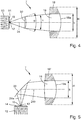
- FIG Figure 4 shows a vertical section through a light module 7 according to the invention, as shown, for example, in FIG Figure 1a is shown. It comprises an LED array 10, a primary lens array 12, a cylindrical lens 30 and a projection lens 18. Thanks to the cylindrical lens 30, the radiation angle of the primary lenses 12 is reduced from ⁇ to ⁇ . The height of the projection lens 18 can thus also be reduced from H to h.
- the part of the conventional projection lens 18 'of the light module known from the prior art which is no longer required in the projection lens 18 of the light module 7 according to the invention is shown hatched. Removing the hatched areas results in a projection lens 18 flattened at the top and bottom with a particularly low overall height.
- FIG. 5 A vertical section through a light module 7 according to the invention is shown, as shown, for example, in FIG Figure 2 is shown. It comprises an LED array 10, a primary lens array 12, a cylinder reflector 33 and a projection lens 18. Thanks to the cylinder reflector 33, the radiation angle of the primary lenses 12 is reduced and the beam path is kinked. The height of the projection lens 18 can thus also be reduced from H to h. The part of the known projection lens 18 ′ which is no longer required for the projection lens 18 of the light module 7 according to the invention is also shown hatched here.
- Figure 6 shows a further embodiment of a light module 7 according to the invention, which is similar to the example Figure 5 is, but with a reflector 36 as secondary optics.
- the reflector 36 is preferably designed as a parabolic reflector. It is also the case here that the cylinder reflector 33 makes the radiation angle of the primary optics 12 more vertical Direction reduced, so that the height of the secondary optics 36 can be significantly reduced compared to conventional light modules without a cylinder reflector.
- the parabolic reflector 36 reproduces the primary light distributions 15 on the roadway (or a measuring screen 20) in front of the motor vehicle, which are enlarged by means of the cylinder reflector 33, as secondary light distributions 19.
- the resulting light distribution 21 of the light module 7 results from a superposition of all active secondary light distributions 19.
- FIGs 7a and 7b the images of the primary lenses 12 are shown, each having an infinitesimally small area of the secondary optics 18; 36 design. Without cylinder optics 30, 33, each secondary lens zone would design largely identical and oriented images of the primary lenses 12. The images of the various secondary optics zones would therefore all have the same shape and size and are merely shifted relative to one another in order to produce the desired light distribution 19. Due to the cylinder optics 30, 33, these images are now all vertically pulled apart in the same way (cf. Figure 7b ). The images of an infinitesimal optic surface are all sharp due to the infinitesimal opening.
- Figure 7a shows a primary light distribution 15 on the indicated light exit surface 16 of a primary optics 12, in particular a converging lens.
- the secondary optics 18, 36 generate the secondary light distributions 19 from these illuminated surfaces 15, which complement one another and form the desired resulting light distribution 21 of the light module 7. Due to the cylindrical optics 30, 33, the illuminated surfaces 15 on the light exit surfaces 16 of the primary optics 12 can be pulled apart in a vertical direction (anamorphic enlargement), so that an enlarged image 38 results (cf. Fig. 7b ). The width of the illuminated areas 15 remains essentially unchanged, ie the width of the enlarged images 38 is essentially the same size as the width of the illuminated ones Surfaces 15 on the light exit surfaces 16 of the primary optics 12.
Landscapes
- Engineering & Computer Science (AREA)
- General Engineering & Computer Science (AREA)
- Physics & Mathematics (AREA)
- Microelectronics & Electronic Packaging (AREA)
- Optics & Photonics (AREA)
- Non-Portable Lighting Devices Or Systems Thereof (AREA)
Claims (15)
- Module d'éclairage (7) d'un projecteur (1) d'un véhicule automobile, comprenant- plusieurs sources lumineuses semi-conductrices (10) destinées à émettre de la lumière, disposées les unes à côté des autres et/ou les unes au-dessus des autres sous la forme d'une matrice et aptes à être commandées individuellement,- plusieurs optiques primaires (12) associées aux sources lumineuses semi-conductrices (10) et disposées les unes à côté des autres et/ou les unes au-dessus des autres sous la forme d'une matrice, destinées à focaliser au moins une partie de la lumière émise par les sources lumineuses semi-conductrices (10), et- une optique secondaire commune (18; 36) destinée à former l'image de répartitions de lumière secondaires (19) sur une chaussée devant le véhicule automobile de façon telle que les répartitions de lumière secondaires (19) éclairent une zone lointaine, les répartitions de lumière secondaires (19) comprenant des coupures verticales (19a) produites par l'optique secondaire (18; 36) et sur les surfaces de sortie de lumière (16) des optiques primaires (12), des répartitions de lumière primaires (15) pouvant être engendrées qui sont susceptibles d'être reproduites par l'optique secondaire (18; 36) sur la chaussée devant le véhicule automobile comme les répartitions de lumière secondaires (19), caractérisé en ce que, sur le trajet de faisceau du module d'éclairage (7), entre les optiques primaires (12) et l'optique secondaire (18; 36), une optique cylindrique (30; 33) est disposée qui, en coupes horizontales, ne présente essentiellement pas de pouvoir de réfraction et qui, en coupes verticales, présente des caractéristiques de focalisation de lumière.
- Module d'éclairage (7) selon la revendication 1, caractérisé en ce que l'optique cylindrique (30; 33) comprend un axe de cylindre (31; 35) qui est orienté sensiblement horizontalement et perpendiculairement à un axe optique (24; 24b) de l'optique secondaire (18; 36).
- Module d'éclairage (7) selon la revendication 1, caractérisé en ce que l'optique cylindrique (30; 33) comprend un axe cylindrique (31; 35) qui est orienté perpendiculairement à une bissectrice d'un angle qui est défini entre un axe optique (24a) d'une optique primaire (12) et un axe optique (24b) d'une optique secondaire (18; 36).
- Module d'éclairage (7) selon l'une des revendications 1 à 3, caractérisé en ce que l'optique cylindrique est formée comme une lentille cylindrique (30) ou comme un réflecteur cylindrique (33).
- Module d'éclairage (7) selon l'une des revendications 1 à 4, caractérisé en ce que l'optique secondaire est formée comme une lentille de projection (18) ou comme un réflecteur secondaire (36).
- Module d'éclairage (7) selon l'une des revendications 1 à 5, caractérisé en ce que les optiques primaires (12) sont formées comme des lentilles convergentes.
- Module d'éclairage (7) selon la revendication 6, caractérisé en ce que les sources lumineuses semi-conductrices (10) sont disposées entre les lentilles convergentes (12) et des foyers du côté objet (F) des lentilles convergentes (12).
- Module d'éclairage (7) selon l'une des revendications 1 à 7, caractérisé en ce que l'optique cylindrique est formée comme un réflecteur cylindrique (33) qui est disposé dans le trajet du rayon de manière telle qu'il plie le trajet du rayon.
- Module d'éclairage (7) selon la revendication 8, caractérisé en ce que le réflecteur cylindrique (33) plie un axe optique (24; 24a, 24b) du module d'éclairage (7) dans un plan horizontal ou vertical.
- Module d'éclairage (7) selon l'une des revendications 1 à 9, caractérisé en ce que l'optique cylindrique (30; 33) effectue un agrandissement anamorphique, d'un multiple, des répartitions de lumière primaires (15) sur les surfaces de sortie de lumière (16) des optiques primaires (12) .
- Module d'éclairage (7) selon la revendication 10, caractérisé en ce que l'optique secondaire est formée comme une lentille de projection (18), la lentille de projection (18) comportant en-haut et/ou en bas une zone aplatie essentiellement horizontalement.
- Module d'éclairage (7) selon l'une des revendications 1 à 11, caractérisé en ce que l'optique secondaire (18; 36) est formée de façon telle que les répartitions de lumière secondaires (19) formées par elle sur la chaussée devant le véhicule, soient directement adjacentes l'une à l'autre, sans que les répartitions de lumière secondaires (19) se chevauchent.
- Module d'éclairage (7) selon l'une des revendications 1 à 11, caractérisé en ce que l'optique secondaire (18; 36) est formée de façon telle que les répartitions de lumière secondaires (19) formées par elle sur la chaussée devant le véhicule soient disposées les unes à côté des autres, des zones au moins latérales de répartitions de lumière secondaires (19) avoisinantes les unes par rapport aux autres se chevauchant l'une l'autre.
- Module d'éclairage (7) selon l'une des revendications 1 à 13, caractérisé en ce que le module d'éclairage (7) est formé pour une désactivation ciblée de sources lumineuses semi-conductrices (10) individuelles dans les répartitions de lumière secondaires (19) desquelles un autre usager de la voie publique est détecté, la désactivation de la (ou des) différente(s) source (s) lumineuse(s) semi-conductrice(s) (10) se produisant en fonction d'un signal de moyens de détection pour la détection d'un autre usager de la voie publique devant le véhicule.
- Projecteur (1) pour un véhicule automobile, comprenant un boîtier (2) avec une ouverture de sortie de la lumière, fermée par une plaque de couverture transparente (5), et au moins un module d'éclairage disposé (6; 7; 8) dans le boîtier (2), caractérisé en ce qu'au moins un module d'éclairage (7) du projecteur (1) est configuré selon l'une des revendications précédentes.
Applications Claiming Priority (1)
| Application Number | Priority Date | Filing Date | Title |
|---|---|---|---|
| DE102014203335.7A DE102014203335A1 (de) | 2014-02-25 | 2014-02-25 | Lichtmodul eines Kraftfahrzeugscheinwerfers und Scheinwerfer mit einem solchen Lichtmodul |
Publications (3)
| Publication Number | Publication Date |
|---|---|
| EP2910847A2 EP2910847A2 (fr) | 2015-08-26 |
| EP2910847A3 EP2910847A3 (fr) | 2015-12-09 |
| EP2910847B1 true EP2910847B1 (fr) | 2020-06-10 |
Family
ID=52358617
Family Applications (1)
| Application Number | Title | Priority Date | Filing Date |
|---|---|---|---|
| EP15150804.1A Active EP2910847B1 (fr) | 2014-02-25 | 2015-01-12 | Module d'éclairage d'un projecteur de véhicule automobile et projecteur avec un tel module d'éclairage |
Country Status (4)
| Country | Link |
|---|---|
| US (1) | US9611996B2 (fr) |
| EP (1) | EP2910847B1 (fr) |
| CN (1) | CN104864333A (fr) |
| DE (1) | DE102014203335A1 (fr) |
Families Citing this family (49)
| Publication number | Priority date | Publication date | Assignee | Title |
|---|---|---|---|---|
| JP6199104B2 (ja) * | 2013-07-19 | 2017-09-20 | 株式会社小糸製作所 | 車両用灯具 |
| FR3048059B1 (fr) * | 2016-02-22 | 2022-08-05 | Valeo Vision | Dispositif de projection de faisceau lumineux muni d'une matrice de sources de lumiere, module d'eclairage et projecteur muni d'un tel dispositif |
| FR3048060B1 (fr) | 2016-02-22 | 2019-04-05 | Valeo Vision | Dispositif de projection de faisceau lumineux muni de sous-matrices de sources de lumiere, module d'eclairage et projecteur muni d'un tel dispositif |
| JP6709651B2 (ja) * | 2016-03-24 | 2020-06-17 | 株式会社小糸製作所 | 車両用灯具、車両用灯具制御システムおよびこれらを備えた車両 |
| KR101795229B1 (ko) * | 2016-03-31 | 2017-11-08 | 현대자동차주식회사 | 차량용 램프 장치 |
| FR3049682A1 (fr) * | 2016-03-31 | 2017-10-06 | Valeo Vision | Module emetteur de lumiere |
| FR3053439B1 (fr) * | 2016-07-01 | 2018-08-10 | Valeo Vision | Dispositif lumineux apte a generer une source a pixels fins |
| DE102016118152A1 (de) * | 2016-09-26 | 2018-03-29 | Automotive Lighting Reutlingen Gmbh | Lichtmodul für einen Kraftfahrzeugscheinwerfer |
| FR3056694B1 (fr) * | 2016-09-29 | 2020-06-19 | Valeo Vision | Dispositif d'eclairage pour vehicule automobile comportant un guide de lumiere |
| FR3056693B1 (fr) * | 2016-09-29 | 2020-06-19 | Valeo Vision | Dispositif d'eclairage en bandes pour projecteur de vehicule automobile |
| FR3058105B1 (fr) * | 2016-10-28 | 2021-04-02 | Valeo Vision | Module optique pour projeter un faisceau lumineux a coupure comportant des moyens de focalisation horizontale |
| FR3061965B1 (fr) * | 2017-01-19 | 2022-08-12 | Valeo Vision | Dispositif de projection d’un faisceau lumineux pixelise, projecteur muni d’un tel dispositif |
| WO2018172140A1 (fr) * | 2017-03-21 | 2018-09-27 | Lumileds Holding B.V. | Module optique et système d'éclairage frontal automobile pour véhicule à moteur |
| FR3065784B1 (fr) * | 2017-04-28 | 2019-10-11 | Valeo Vision | Module lumineux avec optique d'imagerie optimisee pour un modulateur spatial pixellise, destine a un vehicule automobile |
| US10378714B2 (en) * | 2017-07-28 | 2019-08-13 | Sl Corporation | Lamp for vehicle |
| AT520488B1 (de) * | 2017-10-04 | 2019-07-15 | Zkw Group Gmbh | Fahrzeugscheinwerfer |
| DE102017128125B4 (de) * | 2017-11-28 | 2024-02-22 | OSRAM Opto Semiconductors Gesellschaft mit beschränkter Haftung | Scheinwerfer und Betriebsverfahren |
| DE102017222708A1 (de) * | 2017-12-14 | 2019-06-19 | Conti Temic Microelectronic Gmbh | 3D-Umfelderfassung mittels Projektor und Kameramodulen |
| KR102036749B1 (ko) * | 2017-12-14 | 2019-10-28 | 에스엘 주식회사 | 차량용 램프 |
| DE102018103262B4 (de) * | 2018-02-14 | 2024-05-29 | Dr. Ing. H.C. F. Porsche Aktiengesellschaft | Verfahren zum Betreiben einer Beleuchtungsvorrichtung eines Kraftfahrzeugs |
| CN214332559U (zh) * | 2018-05-08 | 2021-10-01 | 亮锐控股有限公司 | 用于汽车车辆的前照灯 |
| EP3578874A1 (fr) * | 2018-06-04 | 2019-12-11 | ZKW Group GmbH | Dispositif d'éclairage pour un phare de véhicule automobile |
| FR3084723B1 (fr) * | 2018-07-31 | 2020-08-28 | Valeo Vision | Module lumineux comportant une matrice de sources lumineuses et un systeme optique bifocal |
| DE102018217215A1 (de) * | 2018-10-09 | 2020-04-09 | Fraunhofer-Gesellschaft zur Förderung der angewandten Forschung e.V. | Abblendlichtscheinwerfer |
| DE102018217213A1 (de) * | 2018-10-09 | 2020-04-09 | Fraunhofer-Gesellschaft zur Förderung der angewandten Forschung e.V. | Fernlichtscheinwerfer |
| CN109611780A (zh) * | 2019-01-29 | 2019-04-12 | 华域视觉科技(上海)有限公司 | 机动车远光照明模组及车灯 |
| CN109210486A (zh) * | 2018-11-01 | 2019-01-15 | 清华大学深圳研究生院 | 一种新型车辆前照灯 |
| TWI803532B (zh) * | 2018-11-02 | 2023-06-01 | 揚明光學股份有限公司 | 圖案投射裝置及其製造方法 |
| CN111221112A (zh) * | 2018-11-27 | 2020-06-02 | 扬明光学股份有限公司 | 图案投射装置及其制造方法 |
| DE102018130512A1 (de) * | 2018-11-30 | 2020-06-04 | HELLA GmbH & Co. KGaA | Beleuchtungsvorrichtung für Fahrzeuge |
| CN109764303A (zh) * | 2018-12-19 | 2019-05-17 | 深圳市九洲光电科技有限公司 | 一种双透镜led灯 |
| MX2021008431A (es) * | 2019-01-14 | 2021-09-08 | Musco Corp | Aparato, metodo y sistema para reducir la humedad en dispositivos de iluminacion led. |
| US11655966B2 (en) | 2019-01-14 | 2023-05-23 | Musco Corporation | Apparatus, method, and system for reducing moisture in LED lighting fixtures |
| DE102019102475A1 (de) * | 2019-01-31 | 2020-08-06 | HELLA GmbH & Co. KGaA | Beleuchtungsvorrichtung für ein Kraftfahrzeug, insbesondere hochauflösender Scheinwerfer |
| DE102019112343A1 (de) * | 2019-05-10 | 2020-11-12 | Automotive Lighting Reutlingen Gmbh | Kraftfahrzeugleuchte |
| EP3819534A1 (fr) * | 2019-11-08 | 2021-05-12 | ZKW Group GmbH | Dispositif d'éclairage pour un phare de véhicule automobile |
| DE102019130464A1 (de) * | 2019-11-12 | 2021-05-12 | Marelli Automotive Lighting Reutlingen (Germany) GmbH | Kraftfahrzeugscheinwerfer |
| CN113669687A (zh) * | 2020-05-15 | 2021-11-19 | 欧司朗大陆有限责任公司 | 用于车辆前照灯的光模块、前照灯及车辆 |
| DE102020122896A1 (de) * | 2020-09-02 | 2022-03-03 | HELLA GmbH & Co. KGaA | Beleuchtungsvorrichtung für ein Kraftfahrzeug |
| DE102020134410A1 (de) | 2020-12-21 | 2022-06-23 | HELLA GmbH & Co. KGaA | Beleuchtungsvorrichtung für Fahrzeuge |
| FR3121498B1 (fr) * | 2021-04-01 | 2023-08-04 | Valeo Vision | Module optique d’un système lumineux d’un véhicule automobile |
| CN115388380B (zh) * | 2021-05-19 | 2026-01-09 | 宁波舜宇车载光学技术有限公司 | 复合透镜、投影系统及其制造方法 |
| EP4399443A1 (fr) | 2021-09-06 | 2024-07-17 | Lumileds LLC | Module del pour phare de véhicule et phare de véhicule doté d'un tel module del |
| KR102597013B1 (ko) | 2021-09-17 | 2023-11-02 | 현대모비스 주식회사 | 차량용 램프 |
| TWI782827B (zh) * | 2021-12-17 | 2022-11-01 | 揚明光學股份有限公司 | 車用投影鏡頭及車用投影機 |
| EP4202289B1 (fr) * | 2021-12-23 | 2024-08-21 | ZKW Group GmbH | Système optique pour un phare de véhicule automobile |
| KR20240039872A (ko) * | 2022-09-20 | 2024-03-27 | 현대모비스 주식회사 | 차량용 램프 |
| EP4596958A4 (fr) * | 2022-09-29 | 2025-12-17 | Koito Mfg Co Ltd | Phare de véhicule |
| CN121358987A (zh) * | 2023-06-29 | 2026-01-16 | 黑拉萨图尔努丝斯洛文尼亚有限责任公司 | 用于机动车辆的光模块和照明装置 |
Family Cites Families (9)
| Publication number | Priority date | Publication date | Assignee | Title |
|---|---|---|---|---|
| DE102006006635A1 (de) * | 2006-02-14 | 2007-08-16 | Schefenacker Vision Systems Germany Gmbh | Abblendlichtscheinwerfer, der einen kontraststark ausgebildeten Cut-off erzeugt |
| DE202007018181U1 (de) * | 2007-12-31 | 2008-05-08 | Automotive Lighting Reutlingen Gmbh | Projektionsmodul mit dynamischer Kurvenlichtfunktion |
| AT508604B1 (de) * | 2009-07-31 | 2012-07-15 | Zizala Lichtsysteme Gmbh | Led-kraftfahrzeugscheinwerfer zur erzeugung einer dynamischen lichtverteilung |
| DE102011077636A1 (de) * | 2011-04-27 | 2011-11-03 | Automotive Lighting Reutlingen Gmbh | Lichtmodul eines Kraftfahrzeugs zur Erzeugung einer Spotverteilung einer Fernlicht-Lichtverteilung und Kraftfahrzeugscheinwerfer mit einem solchen Modul |
| AT511760B1 (de) * | 2011-08-08 | 2013-12-15 | Zizala Lichtsysteme Gmbh | Led-lichtquellenmodul für einen led-kraftfahrzeugscheinwerfer sowie led-kraftfahrzeugscheinwerfer und scheinwerfersystem |
| DE102012008833B4 (de) * | 2012-04-28 | 2018-12-27 | Daimler Ag | Beleuchtungsanordnung und Fahrzeugscheinwerfer |
| DE102012211613A1 (de) * | 2012-07-04 | 2014-01-09 | Automotive Lighting Reutlingen Gmbh | Lichtmodul |
| DE102012223658A1 (de) | 2012-12-18 | 2014-06-18 | Automotive Lighting Reutlingen Gmbh | Kraftfahrzeugscheinwerfer mit einem blendungsfreien Fernlicht |
| DE102013206488A1 (de) * | 2013-04-11 | 2014-10-30 | Automotive Lighting Reutlingen Gmbh | Lichtmodul für eine Kraftfahrzeugbeleuchtungseinrichtung |
-
2014
- 2014-02-25 DE DE102014203335.7A patent/DE102014203335A1/de not_active Ceased
-
2015
- 2015-01-12 EP EP15150804.1A patent/EP2910847B1/fr active Active
- 2015-01-23 CN CN201510036140.9A patent/CN104864333A/zh active Pending
- 2015-02-24 US US14/629,797 patent/US9611996B2/en not_active Expired - Fee Related
Non-Patent Citations (1)
| Title |
|---|
| None * |
Also Published As
| Publication number | Publication date |
|---|---|
| CN104864333A (zh) | 2015-08-26 |
| EP2910847A3 (fr) | 2015-12-09 |
| DE102014203335A1 (de) | 2015-08-27 |
| US9611996B2 (en) | 2017-04-04 |
| US20150241009A1 (en) | 2015-08-27 |
| EP2910847A2 (fr) | 2015-08-26 |
Similar Documents
| Publication | Publication Date | Title |
|---|---|---|
| EP2910847B1 (fr) | Module d'éclairage d'un projecteur de véhicule automobile et projecteur avec un tel module d'éclairage | |
| EP2799761B1 (fr) | Module d'éclairage de phare de véhicule automobile | |
| EP2799762B1 (fr) | Module d'éclairage de phare de véhicule automobile | |
| EP3714205B1 (fr) | Module d'éclairage pour phare de véhicule automobile | |
| EP2789901B1 (fr) | Module d'éclairage pour un dispositif d'éclairage de véhicule automobile | |
| DE102015224745B4 (de) | Kraftfahrzeugscheinwerfer mit einer Grundlichtbaugruppe und einer Fernlichtbaugruppe | |
| EP2505910B1 (fr) | Phare de véhicule automobile équipé d'une source lumineuse semi-conductrice | |
| DE102014200368B4 (de) | Teilfernlicht-Projektionslichtmodul für einen Kraftfahrzeugscheinwerfer | |
| EP3080513B1 (fr) | Dispositif d'éclairage de véhicule automobile | |
| DE102018217215A1 (de) | Abblendlichtscheinwerfer | |
| DE102013206488A1 (de) | Lichtmodul für eine Kraftfahrzeugbeleuchtungseinrichtung | |
| AT517887A1 (de) | Mikroprojektions-Lichtmodul für Fahrzeugscheinwerfer | |
| EP1818599A2 (fr) | Feu de croisement, produisant une coupure à contraste importante | |
| EP3301350B1 (fr) | Module d'éclairage pour phare de véhicule automobile | |
| EP2730836B1 (fr) | Module d'éclairage pour un phare de véhicule automobile | |
| WO2011154470A1 (fr) | Accessoire optique constitué d'un matériau transparent pour la focalisation de lumière, ensemble de lentilles comportant au moins un tel accessoire optique, et module de lumière doté d'un tel ensemble de lentilles | |
| EP2543926A2 (fr) | Lentille pour concentrer la lumière envoyée d'au moins une source de lumière semi-conductrice (LED) | |
| EP1818600A2 (fr) | Feu de croisement doté d'une production d'un point chaud | |
| DE102008027320A1 (de) | Scheinwerfer für Fahrzeuge | |
| EP2840298B1 (fr) | Module lumineux en courbe sans mécanique | |
| DE102017107781A1 (de) | Primäroptikeinheit für ein Lichtmodul | |
| DE102015219211A1 (de) | Lichtmodul für eine Kfz-Beleuchtungseinrichtung | |
| EP3765781B1 (fr) | Module de lumière pour phare de véhicule automobile | |
| EP3230650B1 (fr) | Phare pour véhicules | |
| EP3719391B1 (fr) | Module de feu de route partiel pour un phare de véhicule automobile |
Legal Events
| Date | Code | Title | Description |
|---|---|---|---|
| PUAI | Public reference made under article 153(3) epc to a published international application that has entered the european phase |
Free format text: ORIGINAL CODE: 0009012 |
|
| AK | Designated contracting states |
Kind code of ref document: A2 Designated state(s): AL AT BE BG CH CY CZ DE DK EE ES FI FR GB GR HR HU IE IS IT LI LT LU LV MC MK MT NL NO PL PT RO RS SE SI SK SM TR |
|
| AX | Request for extension of the european patent |
Extension state: BA ME |
|
| PUAL | Search report despatched |
Free format text: ORIGINAL CODE: 0009013 |
|
| AK | Designated contracting states |
Kind code of ref document: A3 Designated state(s): AL AT BE BG CH CY CZ DE DK EE ES FI FR GB GR HR HU IE IS IT LI LT LU LV MC MK MT NL NO PL PT RO RS SE SI SK SM TR |
|
| AX | Request for extension of the european patent |
Extension state: BA ME |
|
| RIC1 | Information provided on ipc code assigned before grant |
Ipc: F21Y 101/02 20060101ALI20151102BHEP Ipc: F21V 7/04 20060101ALI20151102BHEP Ipc: F21S 8/10 20060101AFI20151102BHEP Ipc: B60Q 1/14 20060101ALN20151102BHEP Ipc: F21V 5/04 20060101ALI20151102BHEP |
|
| 17P | Request for examination filed |
Effective date: 20160518 |
|
| RBV | Designated contracting states (corrected) |
Designated state(s): AL AT BE BG CH CY CZ DE DK EE ES FI FR GB GR HR HU IE IS IT LI LT LU LV MC MK MT NL NO PL PT RO RS SE SI SK SM TR |
|
| STAA | Information on the status of an ep patent application or granted ep patent |
Free format text: STATUS: EXAMINATION IS IN PROGRESS |
|
| 17Q | First examination report despatched |
Effective date: 20190212 |
|
| REG | Reference to a national code |
Ref country code: DE Ref legal event code: R079 Ref document number: 502015012748 Country of ref document: DE Free format text: PREVIOUS MAIN CLASS: F21S0008100000 Ipc: F21S0041151000 |
|
| GRAP | Despatch of communication of intention to grant a patent |
Free format text: ORIGINAL CODE: EPIDOSNIGR1 |
|
| STAA | Information on the status of an ep patent application or granted ep patent |
Free format text: STATUS: GRANT OF PATENT IS INTENDED |
|
| RIC1 | Information provided on ipc code assigned before grant |
Ipc: F21Y 115/10 20160101ALI20191204BHEP Ipc: F21S 41/663 20180101ALI20191204BHEP Ipc: F21S 41/33 20180101ALI20191204BHEP Ipc: F21S 41/26 20180101ALI20191204BHEP Ipc: F21S 41/151 20180101AFI20191204BHEP |
|
| INTG | Intention to grant announced |
Effective date: 20200103 |
|
| GRAS | Grant fee paid |
Free format text: ORIGINAL CODE: EPIDOSNIGR3 |
|
| GRAA | (expected) grant |
Free format text: ORIGINAL CODE: 0009210 |
|
| STAA | Information on the status of an ep patent application or granted ep patent |
Free format text: STATUS: THE PATENT HAS BEEN GRANTED |
|
| AK | Designated contracting states |
Kind code of ref document: B1 Designated state(s): AL AT BE BG CH CY CZ DE DK EE ES FI FR GB GR HR HU IE IS IT LI LT LU LV MC MK MT NL NO PL PT RO RS SE SI SK SM TR |
|
| REG | Reference to a national code |
Ref country code: GB Ref legal event code: FG4D Free format text: NOT ENGLISH |
|
| REG | Reference to a national code |
Ref country code: AT Ref legal event code: REF Ref document number: 1279478 Country of ref document: AT Kind code of ref document: T Effective date: 20200615 Ref country code: CH Ref legal event code: EP |
|
| REG | Reference to a national code |
Ref country code: DE Ref legal event code: R096 Ref document number: 502015012748 Country of ref document: DE |
|
| REG | Reference to a national code |
Ref country code: IE Ref legal event code: FG4D Free format text: LANGUAGE OF EP DOCUMENT: GERMAN |
|
| REG | Reference to a national code |
Ref country code: LT Ref legal event code: MG4D |
|
| PG25 | Lapsed in a contracting state [announced via postgrant information from national office to epo] |
Ref country code: SE Free format text: LAPSE BECAUSE OF FAILURE TO SUBMIT A TRANSLATION OF THE DESCRIPTION OR TO PAY THE FEE WITHIN THE PRESCRIBED TIME-LIMIT Effective date: 20200610 Ref country code: LT Free format text: LAPSE BECAUSE OF FAILURE TO SUBMIT A TRANSLATION OF THE DESCRIPTION OR TO PAY THE FEE WITHIN THE PRESCRIBED TIME-LIMIT Effective date: 20200610 Ref country code: GR Free format text: LAPSE BECAUSE OF FAILURE TO SUBMIT A TRANSLATION OF THE DESCRIPTION OR TO PAY THE FEE WITHIN THE PRESCRIBED TIME-LIMIT Effective date: 20200911 Ref country code: NO Free format text: LAPSE BECAUSE OF FAILURE TO SUBMIT A TRANSLATION OF THE DESCRIPTION OR TO PAY THE FEE WITHIN THE PRESCRIBED TIME-LIMIT Effective date: 20200910 Ref country code: FI Free format text: LAPSE BECAUSE OF FAILURE TO SUBMIT A TRANSLATION OF THE DESCRIPTION OR TO PAY THE FEE WITHIN THE PRESCRIBED TIME-LIMIT Effective date: 20200610 |
|
| REG | Reference to a national code |
Ref country code: NL Ref legal event code: MP Effective date: 20200610 |
|
| PG25 | Lapsed in a contracting state [announced via postgrant information from national office to epo] |
Ref country code: RS Free format text: LAPSE BECAUSE OF FAILURE TO SUBMIT A TRANSLATION OF THE DESCRIPTION OR TO PAY THE FEE WITHIN THE PRESCRIBED TIME-LIMIT Effective date: 20200610 Ref country code: BG Free format text: LAPSE BECAUSE OF FAILURE TO SUBMIT A TRANSLATION OF THE DESCRIPTION OR TO PAY THE FEE WITHIN THE PRESCRIBED TIME-LIMIT Effective date: 20200910 Ref country code: LV Free format text: LAPSE BECAUSE OF FAILURE TO SUBMIT A TRANSLATION OF THE DESCRIPTION OR TO PAY THE FEE WITHIN THE PRESCRIBED TIME-LIMIT Effective date: 20200610 Ref country code: HR Free format text: LAPSE BECAUSE OF FAILURE TO SUBMIT A TRANSLATION OF THE DESCRIPTION OR TO PAY THE FEE WITHIN THE PRESCRIBED TIME-LIMIT Effective date: 20200610 |
|
| PG25 | Lapsed in a contracting state [announced via postgrant information from national office to epo] |
Ref country code: NL Free format text: LAPSE BECAUSE OF FAILURE TO SUBMIT A TRANSLATION OF THE DESCRIPTION OR TO PAY THE FEE WITHIN THE PRESCRIBED TIME-LIMIT Effective date: 20200610 Ref country code: AL Free format text: LAPSE BECAUSE OF FAILURE TO SUBMIT A TRANSLATION OF THE DESCRIPTION OR TO PAY THE FEE WITHIN THE PRESCRIBED TIME-LIMIT Effective date: 20200610 |
|
| PG25 | Lapsed in a contracting state [announced via postgrant information from national office to epo] |
Ref country code: SM Free format text: LAPSE BECAUSE OF FAILURE TO SUBMIT A TRANSLATION OF THE DESCRIPTION OR TO PAY THE FEE WITHIN THE PRESCRIBED TIME-LIMIT Effective date: 20200610 Ref country code: IT Free format text: LAPSE BECAUSE OF FAILURE TO SUBMIT A TRANSLATION OF THE DESCRIPTION OR TO PAY THE FEE WITHIN THE PRESCRIBED TIME-LIMIT Effective date: 20200610 Ref country code: EE Free format text: LAPSE BECAUSE OF FAILURE TO SUBMIT A TRANSLATION OF THE DESCRIPTION OR TO PAY THE FEE WITHIN THE PRESCRIBED TIME-LIMIT Effective date: 20200610 Ref country code: RO Free format text: LAPSE BECAUSE OF FAILURE TO SUBMIT A TRANSLATION OF THE DESCRIPTION OR TO PAY THE FEE WITHIN THE PRESCRIBED TIME-LIMIT Effective date: 20200610 Ref country code: PT Free format text: LAPSE BECAUSE OF FAILURE TO SUBMIT A TRANSLATION OF THE DESCRIPTION OR TO PAY THE FEE WITHIN THE PRESCRIBED TIME-LIMIT Effective date: 20201012 Ref country code: CZ Free format text: LAPSE BECAUSE OF FAILURE TO SUBMIT A TRANSLATION OF THE DESCRIPTION OR TO PAY THE FEE WITHIN THE PRESCRIBED TIME-LIMIT Effective date: 20200610 Ref country code: ES Free format text: LAPSE BECAUSE OF FAILURE TO SUBMIT A TRANSLATION OF THE DESCRIPTION OR TO PAY THE FEE WITHIN THE PRESCRIBED TIME-LIMIT Effective date: 20200610 |
|
| PG25 | Lapsed in a contracting state [announced via postgrant information from national office to epo] |
Ref country code: IS Free format text: LAPSE BECAUSE OF FAILURE TO SUBMIT A TRANSLATION OF THE DESCRIPTION OR TO PAY THE FEE WITHIN THE PRESCRIBED TIME-LIMIT Effective date: 20201010 Ref country code: PL Free format text: LAPSE BECAUSE OF FAILURE TO SUBMIT A TRANSLATION OF THE DESCRIPTION OR TO PAY THE FEE WITHIN THE PRESCRIBED TIME-LIMIT Effective date: 20200610 Ref country code: SK Free format text: LAPSE BECAUSE OF FAILURE TO SUBMIT A TRANSLATION OF THE DESCRIPTION OR TO PAY THE FEE WITHIN THE PRESCRIBED TIME-LIMIT Effective date: 20200610 |
|
| REG | Reference to a national code |
Ref country code: DE Ref legal event code: R097 Ref document number: 502015012748 Country of ref document: DE |
|
| PLBE | No opposition filed within time limit |
Free format text: ORIGINAL CODE: 0009261 |
|
| STAA | Information on the status of an ep patent application or granted ep patent |
Free format text: STATUS: NO OPPOSITION FILED WITHIN TIME LIMIT |
|
| PG25 | Lapsed in a contracting state [announced via postgrant information from national office to epo] |
Ref country code: DK Free format text: LAPSE BECAUSE OF FAILURE TO SUBMIT A TRANSLATION OF THE DESCRIPTION OR TO PAY THE FEE WITHIN THE PRESCRIBED TIME-LIMIT Effective date: 20200610 |
|
| 26N | No opposition filed |
Effective date: 20210311 |
|
| PG25 | Lapsed in a contracting state [announced via postgrant information from national office to epo] |
Ref country code: SI Free format text: LAPSE BECAUSE OF FAILURE TO SUBMIT A TRANSLATION OF THE DESCRIPTION OR TO PAY THE FEE WITHIN THE PRESCRIBED TIME-LIMIT Effective date: 20200610 |
|
| PG25 | Lapsed in a contracting state [announced via postgrant information from national office to epo] |
Ref country code: MC Free format text: LAPSE BECAUSE OF FAILURE TO SUBMIT A TRANSLATION OF THE DESCRIPTION OR TO PAY THE FEE WITHIN THE PRESCRIBED TIME-LIMIT Effective date: 20200610 |
|
| REG | Reference to a national code |
Ref country code: CH Ref legal event code: PL |
|
| GBPC | Gb: european patent ceased through non-payment of renewal fee |
Effective date: 20210112 |
|
| PG25 | Lapsed in a contracting state [announced via postgrant information from national office to epo] |
Ref country code: LU Free format text: LAPSE BECAUSE OF NON-PAYMENT OF DUE FEES Effective date: 20210112 |
|
| REG | Reference to a national code |
Ref country code: BE Ref legal event code: MM Effective date: 20210131 |
|
| PG25 | Lapsed in a contracting state [announced via postgrant information from national office to epo] |
Ref country code: LI Free format text: LAPSE BECAUSE OF NON-PAYMENT OF DUE FEES Effective date: 20210131 Ref country code: CH Free format text: LAPSE BECAUSE OF NON-PAYMENT OF DUE FEES Effective date: 20210131 Ref country code: GB Free format text: LAPSE BECAUSE OF NON-PAYMENT OF DUE FEES Effective date: 20210112 |
|
| PG25 | Lapsed in a contracting state [announced via postgrant information from national office to epo] |
Ref country code: IE Free format text: LAPSE BECAUSE OF NON-PAYMENT OF DUE FEES Effective date: 20210112 |
|
| PG25 | Lapsed in a contracting state [announced via postgrant information from national office to epo] |
Ref country code: IS Free format text: LAPSE BECAUSE OF FAILURE TO SUBMIT A TRANSLATION OF THE DESCRIPTION OR TO PAY THE FEE WITHIN THE PRESCRIBED TIME-LIMIT Effective date: 20201010 |
|
| PG25 | Lapsed in a contracting state [announced via postgrant information from national office to epo] |
Ref country code: BE Free format text: LAPSE BECAUSE OF NON-PAYMENT OF DUE FEES Effective date: 20210131 |
|
| PGFP | Annual fee paid to national office [announced via postgrant information from national office to epo] |
Ref country code: AT Payment date: 20221222 Year of fee payment: 9 |
|
| PG25 | Lapsed in a contracting state [announced via postgrant information from national office to epo] |
Ref country code: HU Free format text: LAPSE BECAUSE OF FAILURE TO SUBMIT A TRANSLATION OF THE DESCRIPTION OR TO PAY THE FEE WITHIN THE PRESCRIBED TIME-LIMIT; INVALID AB INITIO Effective date: 20150112 |
|
| P01 | Opt-out of the competence of the unified patent court (upc) registered |
Effective date: 20230508 |
|
| PG25 | Lapsed in a contracting state [announced via postgrant information from national office to epo] |
Ref country code: CY Free format text: LAPSE BECAUSE OF FAILURE TO SUBMIT A TRANSLATION OF THE DESCRIPTION OR TO PAY THE FEE WITHIN THE PRESCRIBED TIME-LIMIT Effective date: 20200610 |
|
| PG25 | Lapsed in a contracting state [announced via postgrant information from national office to epo] |
Ref country code: MK Free format text: LAPSE BECAUSE OF FAILURE TO SUBMIT A TRANSLATION OF THE DESCRIPTION OR TO PAY THE FEE WITHIN THE PRESCRIBED TIME-LIMIT Effective date: 20200610 |
|
| REG | Reference to a national code |
Ref country code: AT Ref legal event code: MM01 Ref document number: 1279478 Country of ref document: AT Kind code of ref document: T Effective date: 20240112 |
|
| PG25 | Lapsed in a contracting state [announced via postgrant information from national office to epo] |
Ref country code: MT Free format text: LAPSE BECAUSE OF FAILURE TO SUBMIT A TRANSLATION OF THE DESCRIPTION OR TO PAY THE FEE WITHIN THE PRESCRIBED TIME-LIMIT Effective date: 20200610 |
|
| PG25 | Lapsed in a contracting state [announced via postgrant information from national office to epo] |
Ref country code: AT Free format text: LAPSE BECAUSE OF NON-PAYMENT OF DUE FEES Effective date: 20240112 |
|
| PG25 | Lapsed in a contracting state [announced via postgrant information from national office to epo] |
Ref country code: AT Free format text: LAPSE BECAUSE OF NON-PAYMENT OF DUE FEES Effective date: 20240112 |
|
| PG25 | Lapsed in a contracting state [announced via postgrant information from national office to epo] |
Ref country code: TR Free format text: LAPSE BECAUSE OF FAILURE TO SUBMIT A TRANSLATION OF THE DESCRIPTION OR TO PAY THE FEE WITHIN THE PRESCRIBED TIME-LIMIT Effective date: 20200610 |
|
| PGFP | Annual fee paid to national office [announced via postgrant information from national office to epo] |
Ref country code: FR Payment date: 20251217 Year of fee payment: 12 |
|
| REG | Reference to a national code |
Ref country code: DE Ref legal event code: R081 Ref document number: 502015012748 Country of ref document: DE Owner name: MARELLI GERMANY GMBH, DE Free format text: FORMER OWNER: AUTOMOTIVE LIGHTING REUTLINGEN GMBH, 72762 REUTLINGEN, DE |
|
| PGFP | Annual fee paid to national office [announced via postgrant information from national office to epo] |
Ref country code: DE Payment date: 20251217 Year of fee payment: 12 |