EP2789934A1 - Séparateur d'huile avec élément intégré connu en tant que séparateur d'huile d'onduleur retex formé par un tube avec des découpes ou des trous, de la laine métallique, un treillis métallique - Google Patents
Séparateur d'huile avec élément intégré connu en tant que séparateur d'huile d'onduleur retex formé par un tube avec des découpes ou des trous, de la laine métallique, un treillis métallique Download PDFInfo
- Publication number
- EP2789934A1 EP2789934A1 EP14163826.2A EP14163826A EP2789934A1 EP 2789934 A1 EP2789934 A1 EP 2789934A1 EP 14163826 A EP14163826 A EP 14163826A EP 2789934 A1 EP2789934 A1 EP 2789934A1
- Authority
- EP
- European Patent Office
- Prior art keywords
- oil separator
- oil
- cuts
- tube
- holes
- Prior art date
- Legal status (The legal status is an assumption and is not a legal conclusion. Google has not performed a legal analysis and makes no representation as to the accuracy of the status listed.)
- Withdrawn
Links
Images


Classifications
-
- F—MECHANICAL ENGINEERING; LIGHTING; HEATING; WEAPONS; BLASTING
- F25—REFRIGERATION OR COOLING; COMBINED HEATING AND REFRIGERATION SYSTEMS; HEAT PUMP SYSTEMS; MANUFACTURE OR STORAGE OF ICE; LIQUEFACTION SOLIDIFICATION OF GASES
- F25B—REFRIGERATION MACHINES, PLANTS OR SYSTEMS; COMBINED HEATING AND REFRIGERATION SYSTEMS; HEAT PUMP SYSTEMS
- F25B43/00—Arrangements for separating or purifying gases or liquids; Arrangements for vaporising the residuum of liquid refrigerant, e.g. by heat
- F25B43/003—Filters
-
- F—MECHANICAL ENGINEERING; LIGHTING; HEATING; WEAPONS; BLASTING
- F25—REFRIGERATION OR COOLING; COMBINED HEATING AND REFRIGERATION SYSTEMS; HEAT PUMP SYSTEMS; MANUFACTURE OR STORAGE OF ICE; LIQUEFACTION SOLIDIFICATION OF GASES
- F25B—REFRIGERATION MACHINES, PLANTS OR SYSTEMS; COMBINED HEATING AND REFRIGERATION SYSTEMS; HEAT PUMP SYSTEMS
- F25B43/00—Arrangements for separating or purifying gases or liquids; Arrangements for vaporising the residuum of liquid refrigerant, e.g. by heat
- F25B43/02—Arrangements for separating or purifying gases or liquids; Arrangements for vaporising the residuum of liquid refrigerant, e.g. by heat for separating lubricants from the refrigerant
Definitions
- the present invention relates to an oil separator with the function of separating oil from a gas in output from a compressor, particularly for industrial and civil refrigeration and conditioning systems.
- separators are currently used which comprise glass wool fiber filters.
- the aim of the present invention is to provide an oil separator that is capable of ensuring optimum oil separation without fragmentation of the filter contained therein.
- an object of the invention is to provide an oil separator that ensures constant separation and cleaning of the gas in output over time.
- Another object of the invention is to provide an oil separator that can be provided by means of known materials, such as for example carbon steel and/or stainless steel.
- an oil separator having the function of separating oil from a gas in output from a compressor, characterized in that it comprises a filter constituted by a tube with cuts or holes, wrapped in a layer of metal wool or the like, enclosed by a cartridge made of metal fabric of at least two layers of metal fabric.
- an oil separator is designated generally by the reference numeral 10.
- Such oil separator 10 has the function of separating oil from a gas in output from a compressor, and can be used in particular in the field of industrial and civil refrigeration and in industrial and civil conditioning.
- the oil separator is installed in the machines along the delivery line behind the compressor: it has the purpose of separating the oil in the vapor or gaseous state, present in the refrigerating gas or other gas, at the output of the compressor.
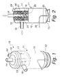
- the oil separator 10 comprises a substantially cylindrical tank 11, which is closed in an upper region by a lid 12 and in a lower region by an oil collection pan 13.
- An upper connecting sleeve 14 is fixed on the lid 12 for the inflow of the gas that exits from a compressor, the upper sleeve 14 being coaxial with the cylindrical tubular body 15 of the tank 11 and with a corresponding hole formed in the lid 12 for the passage of gas.
- a lateral connecting sleeve 16 for the outflow of the gas separated from the oil is fixed radially to the cylindrical tubular body 15 in the upper part thereof, at a complementarily shaped gas passage hole.
- a filter 17 is present inside the tank 11.
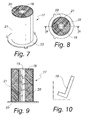
- the filter 17 is constituted by a tube 18 with cuts or holes 19, wrapped in a layer of metal wool 20, or the like, enclosed by a cartridge made of metal fabric 21 of at least two layers of metal fabric.
- the filter 11 is carried by a supporting diaphragm disk 22, which closes the tube 18 in a downward region.
- the metal fabric of the metal fabric cartridge 21 has a passage section smaller than 80 microns.
- the through cuts 19 are substantially L-shaped, as shown in Figure 10 , with an angular portion that is directed downward in the configuration for use.
- the tube 118 is provided with circular through holes 119.
- the cuts or holes 18 and 118 are to be understood as being providable also with other shapes and arranged inclined or vertically or horizontally with respect to a configuration for use, depending on the needs and the technical requirements.
- the tube 18 or 118 of the filter 17 is fixed coaxially to the first sleeve 14, as shown in Figure 4 ; fixing is provided for example by welding.
- the tube 18 and 118 with cuts (or holes) in the wall which are inclined, vertical or horizontal, ensures a slowing of the input gas stream, creating a uniform gas distribution in the entire region of the filter, regardless of the length, of the diameter, of the number of cuts, of the inclination of the cuts, of the cross-section of the cuts, of the placement of the holes, of the diameter of the holes.
- the layer of metal wool 20 or the like is useful in the first separation stage and allows separating the gas from the oil; the gas mixed with oil is filtered through the meshes of the metal wool (or the like), allowing the gas to exit in a clean state, and allows the vaporized oil to begin to condense, forming micro-droplets.
- the metallic cartridge 21, made of metallic fabric with a passage smaller than 80 microns, has at least two turns, i.e., windings, so as to obtain a degree of filtration smaller than 10 microns; in this manner, in fact, the metal cartridge 21 makes it possible to retain any oil residues.
- Such metal cartridge 21 is necessary for the second separation step, since it facilitates the growth of the drops that have condensed in the metal wool 20 (or the like).
- the diaphragm disk 22 is necessary to ensure a calm region in the lower part of the separator 10.
- the separator 10 also comprises, inside the cylindrical tubular body 15, at the lateral connecting sleeve 16 and interposed between the filter 17 and the inlet of said lateral sleeve 16, an internal partition 23, which is adapted to prevent any pressurized oil splashes from being introduced into the lateral sleeve 16, which is intended for the outflow of the gas separated from the oil.
- the separator 10 also comprises an additional sleeve 24 for the insertion of a safety valve; the sleeve 24 is arranged for example on the lid 12 of the tank 11, in a position that is not affected by the filter 17.
- the gas enters the inside of the tube 18 or 118 provided with cuts that are inclined, vertical or horizontal (or holes 119) and distribute it uniformly within the metal wool 20 (or the like), creating a flow slowdown.
- the gas mixed with the vaporized oil passes through the metal wool 20 (or the like), creating the first separation stage; the vaporized oil is condensed by forming micro-drops.
- the second separation stage is entered, in which the gas passes through the metal fabric cartridge 21 (a minimum of two turns around the metal wool and a weft section smaller than 80 microns) so as to bring the degree of filtration below 10 microns: the weight of the micro-drops is thus increased and they are forced by gravity to precipitate into the lower part of the tank 11 in the oil collection region 25, where the residual oil vapors are retained.
- the condensed oil can be reintroduced into the lubrication circuit of the compressors.
- the diaphragm disk 22 In the lower part of the filter 17 the diaphragm disk 22 is located, which ensures a calm region in the part where the separated oil is settled, allowing the oil to be free from foam at the outlet through the capillary tube.
- the resulting 99.8% oil separation thus achieved is independent of the size of the pipe, of the geometry of the cuts (or holes), of the consistency of the metal wool and of the degree of filtration of the metal fabric.
- the invention provides an oil separator that is capable of ensuring an optimum oil separation without fragmentation of the filter contained therein.
- the invention provides an oil separator that ensures a separation and cleaning of the gas in output that are constant over time and a 99.8% degree of filtration of the oil from the gas.
- the invention provides an oil separator the filter of which can be made of known materials, such as for example carbon steel and/or stainless steel.
- the oil separator 10 according to the invention is to be intended for all industrial and civil refrigeration and conditioning systems and can be provided according to the power requirements of the refrigeration machine with which it is associated.
- the materials used may be any according to the requirements and the state of the art.
Landscapes
- Engineering & Computer Science (AREA)
- Chemical & Material Sciences (AREA)
- Analytical Chemistry (AREA)
- Power Engineering (AREA)
- Physics & Mathematics (AREA)
- Mechanical Engineering (AREA)
- Thermal Sciences (AREA)
- General Engineering & Computer Science (AREA)
- Lubrication Details And Ventilation Of Internal Combustion Engines (AREA)
- Filtering Of Dispersed Particles In Gases (AREA)
- Filtering Materials (AREA)
Applications Claiming Priority (1)
| Application Number | Priority Date | Filing Date | Title |
|---|---|---|---|
| IT000091A ITPD20130091A1 (it) | 2013-04-10 | 2013-04-10 | Separatore olio con elemento integrato denominato elemento separatore olio retex inverter formato da un tubo con taglio o fori, lana metallica, rete metallica |
Publications (1)
| Publication Number | Publication Date |
|---|---|
| EP2789934A1 true EP2789934A1 (fr) | 2014-10-15 |
Family
ID=49485150
Family Applications (1)
| Application Number | Title | Priority Date | Filing Date |
|---|---|---|---|
| EP14163826.2A Withdrawn EP2789934A1 (fr) | 2013-04-10 | 2014-04-08 | Séparateur d'huile avec élément intégré connu en tant que séparateur d'huile d'onduleur retex formé par un tube avec des découpes ou des trous, de la laine métallique, un treillis métallique |
Country Status (2)
| Country | Link |
|---|---|
| EP (1) | EP2789934A1 (fr) |
| IT (1) | ITPD20130091A1 (fr) |
Cited By (5)
| Publication number | Priority date | Publication date | Assignee | Title |
|---|---|---|---|---|
| CN105240278A (zh) * | 2015-11-12 | 2016-01-13 | 武汉格瑞拓机械有限公司 | 一种沼气螺杆压缩机组用油气分离器 |
| EP3034965A1 (fr) * | 2014-12-19 | 2016-06-22 | Johnson Controls Denmark ApS | Condenseur bloc et plaque, procédé d'extraction d'huile à partir d'un fluide frigorigène et utilisation d'un tel condenseur |
| CN106568246A (zh) * | 2016-11-17 | 2017-04-19 | 珠海格力电器股份有限公司 | 一种油分离器及空调机组 |
| IT201800005138A1 (it) * | 2018-05-08 | 2019-11-08 | Filtro perfezionato per separatori d'olio per circuiti frigoriferi e separatore di olio con tale filtro | |
| EP3705815A3 (fr) * | 2019-03-06 | 2020-11-04 | Sumitomo Heavy Industries, Ltd. | Séparateur d'huile, élément de filtre et compresseur pour cryoréfrigérateur |
Citations (6)
| Publication number | Priority date | Publication date | Assignee | Title |
|---|---|---|---|---|
| GB2007992A (en) * | 1977-11-08 | 1979-05-31 | Mann & Hummel Filter | Annular filter insert |
| US4516994A (en) * | 1984-04-11 | 1985-05-14 | Vilter Manufacturing Corporation | Apparatus for separating liquid droplets from gas |
| EP0335571A2 (fr) * | 1988-04-01 | 1989-10-04 | Pall Corporation | Elément de traitement de fluide enveloppé en spirale |
| GB2261830A (en) * | 1991-11-26 | 1993-06-02 | Process Scient Innovations | Gas filter |
| US6962615B2 (en) * | 2002-05-31 | 2005-11-08 | Mann & Hummel Gmbh | Filter element, particularly for separating a liquid from a gas stream |
| US20070028571A1 (en) * | 2005-08-04 | 2007-02-08 | Johnson Controls Technology Company | Coalescing filter element with drainage mechanism |
-
2013
- 2013-04-10 IT IT000091A patent/ITPD20130091A1/it unknown
-
2014
- 2014-04-08 EP EP14163826.2A patent/EP2789934A1/fr not_active Withdrawn
Patent Citations (6)
| Publication number | Priority date | Publication date | Assignee | Title |
|---|---|---|---|---|
| GB2007992A (en) * | 1977-11-08 | 1979-05-31 | Mann & Hummel Filter | Annular filter insert |
| US4516994A (en) * | 1984-04-11 | 1985-05-14 | Vilter Manufacturing Corporation | Apparatus for separating liquid droplets from gas |
| EP0335571A2 (fr) * | 1988-04-01 | 1989-10-04 | Pall Corporation | Elément de traitement de fluide enveloppé en spirale |
| GB2261830A (en) * | 1991-11-26 | 1993-06-02 | Process Scient Innovations | Gas filter |
| US6962615B2 (en) * | 2002-05-31 | 2005-11-08 | Mann & Hummel Gmbh | Filter element, particularly for separating a liquid from a gas stream |
| US20070028571A1 (en) * | 2005-08-04 | 2007-02-08 | Johnson Controls Technology Company | Coalescing filter element with drainage mechanism |
Cited By (7)
| Publication number | Priority date | Publication date | Assignee | Title |
|---|---|---|---|---|
| EP3034965A1 (fr) * | 2014-12-19 | 2016-06-22 | Johnson Controls Denmark ApS | Condenseur bloc et plaque, procédé d'extraction d'huile à partir d'un fluide frigorigène et utilisation d'un tel condenseur |
| WO2016095919A1 (fr) * | 2014-12-19 | 2016-06-23 | Johnson Controls Denmark Aps | Condenseur à enveloppe et à plaques, procédé d'élimination d'huile d'un fluide frigorigène et utilisation d'un condenseur à enveloppe et à plaques |
| CN105240278A (zh) * | 2015-11-12 | 2016-01-13 | 武汉格瑞拓机械有限公司 | 一种沼气螺杆压缩机组用油气分离器 |
| CN106568246A (zh) * | 2016-11-17 | 2017-04-19 | 珠海格力电器股份有限公司 | 一种油分离器及空调机组 |
| CN106568246B (zh) * | 2016-11-17 | 2023-10-20 | 珠海格力电器股份有限公司 | 一种油分离器及空调机组 |
| IT201800005138A1 (it) * | 2018-05-08 | 2019-11-08 | Filtro perfezionato per separatori d'olio per circuiti frigoriferi e separatore di olio con tale filtro | |
| EP3705815A3 (fr) * | 2019-03-06 | 2020-11-04 | Sumitomo Heavy Industries, Ltd. | Séparateur d'huile, élément de filtre et compresseur pour cryoréfrigérateur |
Also Published As
| Publication number | Publication date |
|---|---|
| ITPD20130091A1 (it) | 2014-10-11 |
Similar Documents
| Publication | Publication Date | Title |
|---|---|---|
| EP2789934A1 (fr) | Séparateur d'huile avec élément intégré connu en tant que séparateur d'huile d'onduleur retex formé par un tube avec des découpes ou des trous, de la laine métallique, un treillis métallique | |
| EP2673576B1 (fr) | Dispositif de séparation de gouttelettes et utilisation d'un tel dispositif | |
| JP4857350B2 (ja) | ファイバーベッド組立体及びそのためのファイバーベッド | |
| US20140096683A1 (en) | Fiber bed assembly including a re-entrainment control device for a fiber bed mist eliminator | |
| US8741015B2 (en) | Multistage oil separator | |
| JP2007283291A (ja) | 気体から液滴を分離する多段分離装置、分離方法、および空気圧縮装置 | |
| CN204285910U (zh) | 一种压缩机用储液器 | |
| EP3479888B1 (fr) | Séparateur gaz/liquide | |
| CN217119758U (zh) | 一种一体式重力分离器 | |
| US6640559B1 (en) | Vertical oil separator for a chiller system | |
| US20200224649A1 (en) | Separation device and oil separating air filter assembly comprising such separation device as well as method for separating fluid from a gas stream deriving from a connecting device | |
| EP3261745B1 (fr) | Séparateur d'huile pour usines de réfrigération et/ou de climatisation | |
| EP3705815B1 (fr) | Séparateur d'huile, élément de filtre et compresseur pour cryoréfrigérateur | |
| US11828500B2 (en) | Evaporator with improved droplet separation | |
| JP2005069654A (ja) | 油分離器 | |
| JP2010048483A (ja) | 気液分離器並びにこれを搭載した空気圧縮装置および空気調和装置 | |
| JP2006029684A (ja) | オイルセパレータ及び極低温装置 | |
| CN107356029B (zh) | 冷凝器壳管和制冷设备 | |
| CN105327575A (zh) | 一种用于气固分离的装置 | |
| JP2018094530A (ja) | 油中水分除去装置、油中水分除去方法及び真空ポンプシステム | |
| RU2159905C1 (ru) | Секционный маслоотделитель для холодильных винтовых маслозаполненных компрессоров | |
| JP2022049194A (ja) | 油分離エレメント、油分離器及び圧縮システム | |
| KR20190137370A (ko) | 기체-오일 분리기 | |
| US3578168A (en) | Refrigerating apparatus having oil-separating means | |
| CN109847492A (zh) | 用于从空气流分离油颗粒的装置和方法 |
Legal Events
| Date | Code | Title | Description |
|---|---|---|---|
| PUAI | Public reference made under article 153(3) epc to a published international application that has entered the european phase |
Free format text: ORIGINAL CODE: 0009012 |
|
| 17P | Request for examination filed |
Effective date: 20140408 |
|
| AK | Designated contracting states |
Kind code of ref document: A1 Designated state(s): AL AT BE BG CH CY CZ DE DK EE ES FI FR GB GR HR HU IE IS IT LI LT LU LV MC MK MT NL NO PL PT RO RS SE SI SK SM TR |
|
| AX | Request for extension of the european patent |
Extension state: BA ME |
|
| R17P | Request for examination filed (corrected) |
Effective date: 20150324 |
|
| RBV | Designated contracting states (corrected) |
Designated state(s): AL AT BE BG CH CY CZ DE DK EE ES FI FR GB GR HR HU IE IS IT LI LT LU LV MC MK MT NL NO PL PT RO RS SE SI SK SM TR |
|
| RIN1 | Information on inventor provided before grant (corrected) |
Inventor name: MAGGIOLO,GIANCARLO Inventor name: NERICCIO, NICOLA Inventor name: MAGGIOLO, MAURIZIO |
|
| STAA | Information on the status of an ep patent application or granted ep patent |
Free format text: STATUS: EXAMINATION IS IN PROGRESS |
|
| 17Q | First examination report despatched |
Effective date: 20201201 |
|
| P01 | Opt-out of the competence of the unified patent court (upc) registered |
Effective date: 20230529 |
|
| STAA | Information on the status of an ep patent application or granted ep patent |
Free format text: STATUS: THE APPLICATION IS DEEMED TO BE WITHDRAWN |
|
| 18D | Application deemed to be withdrawn |
Effective date: 20250529 |