EP2792437A1 - Procédé de fabrication d'un tube d'évaporateur - Google Patents
Procédé de fabrication d'un tube d'évaporateur Download PDFInfo
- Publication number
- EP2792437A1 EP2792437A1 EP14157192.7A EP14157192A EP2792437A1 EP 2792437 A1 EP2792437 A1 EP 2792437A1 EP 14157192 A EP14157192 A EP 14157192A EP 2792437 A1 EP2792437 A1 EP 2792437A1
- Authority
- EP
- European Patent Office
- Prior art keywords
- inner tube
- producing
- evaporator tube
- tube according
- evaporator
- Prior art date
- Legal status (The legal status is an assumption and is not a legal conclusion. Google has not performed a legal analysis and makes no representation as to the accuracy of the status listed.)
- Granted
Links
- 238000004519 manufacturing process Methods 0.000 title claims abstract description 23
- 239000000463 material Substances 0.000 claims abstract description 59
- 238000000034 method Methods 0.000 claims abstract description 30
- 238000005245 sintering Methods 0.000 claims abstract description 24
- 239000000843 powder Substances 0.000 claims description 8
- 239000002184 metal Substances 0.000 claims description 5
- 229910001220 stainless steel Inorganic materials 0.000 claims description 5
- 239000010935 stainless steel Substances 0.000 claims description 5
- 239000000853 adhesive Substances 0.000 claims description 4
- 239000000155 melt Substances 0.000 claims description 4
- 238000005476 soldering Methods 0.000 claims description 4
- 230000001070 adhesive effect Effects 0.000 claims description 3
- 239000003795 chemical substances by application Substances 0.000 claims description 2
- 238000010438 heat treatment Methods 0.000 claims description 2
- 239000002861 polymer material Substances 0.000 claims description 2
- 230000002277 temperature effect Effects 0.000 claims 1
- 230000008016 vaporization Effects 0.000 abstract description 2
- 238000001704 evaporation Methods 0.000 description 11
- 230000008020 evaporation Effects 0.000 description 10
- 238000005086 pumping Methods 0.000 description 4
- 238000002485 combustion reaction Methods 0.000 description 3
- 239000007788 liquid Substances 0.000 description 3
- 125000006850 spacer group Chemical group 0.000 description 3
- 238000012546 transfer Methods 0.000 description 3
- 238000004220 aggregation Methods 0.000 description 2
- 230000002776 aggregation Effects 0.000 description 2
- 239000000446 fuel Substances 0.000 description 2
- 238000003754 machining Methods 0.000 description 2
- 239000002245 particle Substances 0.000 description 2
- 238000004026 adhesive bonding Methods 0.000 description 1
- 150000001408 amides Chemical class 0.000 description 1
- 230000001419 dependent effect Effects 0.000 description 1
- 238000013461 design Methods 0.000 description 1
- 239000002803 fossil fuel Substances 0.000 description 1
- 238000003306 harvesting Methods 0.000 description 1
- 238000013021 overheating Methods 0.000 description 1
- 235000011837 pasties Nutrition 0.000 description 1
- 230000002093 peripheral effect Effects 0.000 description 1
- 238000012805 post-processing Methods 0.000 description 1
- 238000012545 processing Methods 0.000 description 1
- 230000001681 protective effect Effects 0.000 description 1
- 230000000717 retained effect Effects 0.000 description 1
- 239000007787 solid Substances 0.000 description 1
- 238000007711 solidification Methods 0.000 description 1
- 230000008023 solidification Effects 0.000 description 1
- 229910001256 stainless steel alloy Inorganic materials 0.000 description 1
Images

Classifications
-
- B—PERFORMING OPERATIONS; TRANSPORTING
- B22—CASTING; POWDER METALLURGY
- B22F—WORKING METALLIC POWDER; MANUFACTURE OF ARTICLES FROM METALLIC POWDER; MAKING METALLIC POWDER; APPARATUS OR DEVICES SPECIALLY ADAPTED FOR METALLIC POWDER
- B22F5/00—Manufacture of workpieces or articles from metallic powder characterised by the special shape of the product
- B22F5/10—Manufacture of workpieces or articles from metallic powder characterised by the special shape of the product of articles with cavities or holes, not otherwise provided for in the preceding subgroups
- B22F5/106—Tube or ring forms
-
- B—PERFORMING OPERATIONS; TRANSPORTING
- B22—CASTING; POWDER METALLURGY
- B22F—WORKING METALLIC POWDER; MANUFACTURE OF ARTICLES FROM METALLIC POWDER; MAKING METALLIC POWDER; APPARATUS OR DEVICES SPECIALLY ADAPTED FOR METALLIC POWDER
- B22F3/00—Manufacture of workpieces or articles from metallic powder characterised by the manner of compacting or sintering; Apparatus specially adapted therefor ; Presses and furnaces
- B22F3/10—Sintering only
- B22F3/11—Making porous workpieces or articles
- B22F3/1121—Making porous workpieces or articles by using decomposable, meltable or sublimatable fillers
-
- B—PERFORMING OPERATIONS; TRANSPORTING
- B22—CASTING; POWDER METALLURGY
- B22F—WORKING METALLIC POWDER; MANUFACTURE OF ARTICLES FROM METALLIC POWDER; MAKING METALLIC POWDER; APPARATUS OR DEVICES SPECIALLY ADAPTED FOR METALLIC POWDER
- B22F7/00—Manufacture of composite layers, workpieces, or articles, comprising metallic powder, by sintering the powder, with or without compacting wherein at least one part is obtained by sintering or compression
- B22F7/06—Manufacture of composite layers, workpieces, or articles, comprising metallic powder, by sintering the powder, with or without compacting wherein at least one part is obtained by sintering or compression of composite workpieces or articles from parts, e.g. to form tipped tools
- B22F7/08—Manufacture of composite layers, workpieces, or articles, comprising metallic powder, by sintering the powder, with or without compacting wherein at least one part is obtained by sintering or compression of composite workpieces or articles from parts, e.g. to form tipped tools with one or more parts not made from powder
-
- B—PERFORMING OPERATIONS; TRANSPORTING
- B22—CASTING; POWDER METALLURGY
- B22F—WORKING METALLIC POWDER; MANUFACTURE OF ARTICLES FROM METALLIC POWDER; MAKING METALLIC POWDER; APPARATUS OR DEVICES SPECIALLY ADAPTED FOR METALLIC POWDER
- B22F3/00—Manufacture of workpieces or articles from metallic powder characterised by the manner of compacting or sintering; Apparatus specially adapted therefor ; Presses and furnaces
- B22F3/10—Sintering only
- B22F2003/1042—Sintering only with support for articles to be sintered
Definitions
- the present invention relates to a method for producing an evaporator tube according to the features in the preamble of claim 1.
- the object of the present invention is to demonstrate a production method for an evaporator tube that is considerably simpler and at the same time less expensive to carry out than the production method known from the prior art, wherein the evaporator tube produced thereby has improved heat transfer properties.
- a placeholder material is used which melts at the occurring sintering temperatures and flows out of the channel system or evaporates. There, where the placeholder material was arranged, thus creating a channel system on the outer circumferential surface of the inner tube.
- the outer shape is preferably a jacket tube.
- the outer shape may also be formed as a wire mesh.
- the jacket tube may be circular or elliptical in cross-section. In the longitudinal direction, the jacket tube can also be conical.
- a capillary structure is generated due to a porosity of the sintered material, so that the second medium flows through the resulting channels through the second channel and from the first channel via the inner tube, a heat flow is introduced from the first medium into the second medium.
- the second medium evaporates such that the resulting vapor is removed via steam channels.
- the steam is then converted to a condenser again in the liquid state and this additional energy is recovered, which is withdrawn at the first channel in particular in the form of an exhaust gas passage to the exhaust gas. Due to the capillary action, liquid medium flows into the sintering structure simultaneously with the evaporation.
- the workgroup process can be carried out, for example, according to the principle of a Clausius-Rankine process.
- the evaporator tubes are designed as a heat pipe, and consequently as heat pipes, and particularly preferably as a loopheat pipe.
- the inventive method eliminates entirely a mechanical machining of the tube assembly produced.
- the necessary steps are limited to a minimum, with elaborate machining preliminary or post-processing eliminated altogether.
- the sintering process itself produces a sufficiently high porosity in the sintered layer, so that an optimum pumping action and consequently a removal of the vapor is made possible.
- a plastic material is used in particular for the placeholder material itself, this being in particular a polymer material.
- an amide wax can also be used.
- the such placeholder material is applied in particular to the outer circumferential surface or wound or sprayed.
- an adhesive is applied to the outer circumferential surface, wherein the adhesive produces a better cohesive connection between outer lateral surface and spacer material and / or outer lateral surface and sintered material.
- the placeholder material is particularly preferably provided, for example, in the solid state of matter, and very particularly preferably in strand form.
- the strands of the placeholder material of this type are then placed or pressed onto the outer circumferential surface and glued to the outer lateral surface at least temporarily.
- the strands are pressed or glued.
- the placeholder material is applied in strip form, wherein the strips, represented by the strands, are preferably spaced parallel to one another.
- the strips continue to run in particular parallel to the central longitudinal axis of the inner tube or else the strips are applied helically on the outer circumferential surface.
- the strips extend at an angle to the central longitudinal axis of the inner tube and wind helically around the outer circumferential surface.
- the placeholder material is sprayed in a liquid, gel or pasty state of aggregation on the outer circumferential surface.
- the placeholder material has a self-adhesive function in this state of aggregation, so that an additional gluing process does not have to be carried out.
- the placeholder material melts and flows out of the annular gap.
- the temperatures used are preferably 500 ° to 1200 ° C, in particular 900 ° to 1100 ° C.
- the placeholder material melts and runs out of the arrangement via the resulting channels.
- the placeholder material can be expelled at about 600 ° before solidification of the sintered material and then the actual sintering process can be performed.
- the placeholder material itself begins in a temperature range between 150 ° C and 450 ° C, in particular 200 ° C to 400 ° C to melt or vaporize.
- the assembly has further reached a temperature at which the sintering process has already begun, whereby the sintered material then begins to bond.
- a sintered material explained below in the form of a spattered metal powder, however, it can also be ensured that even if the spacer material is almost completely flowed out or vaporized, first of all the channel structure produced is retained during the subsequent sintering process.
- a spattered metal powder is used.
- Under spratzigem metal powder is an angular and / or edged powder form to understand so that the individual powder particles interlock with each other and / or tilt and remain dimensionally stable to each other until the completion of the sintering process.
- the powder particles are thus square or edged or polygonal designed such that they interlock with each other and / or tilt. Due to the resulting channel structures, the second medium, in particular a working medium, then flows in the gaseous state of matter during later use.
- the pumping function is to be regarded as being so preferred that an active pump can be dispensed with and the pumping function is effected exclusively by the capillary function.
- a stainless steel material is used for the sintered material.
- the inner tube, the sintered material and the optional jacket tube are likewise made of a stainless steel material, since this has a particularly good resistance to the corrosive properties of the exhaust gas while at the same time having good thermal conductivity. If all component components are formed from the same material, then the material has correspondingly equal thermal expansion coefficients, so that the arrangement assumes no damage, in particular with regard to the durability under thermal expansion.
- the inner tube, the sintered material and optionally the jacket tube are made of a stainless steel material of the 1.4XXX group, most preferably of a stainless steel alloy 1.4404.
- the sintered layer produced from the sintered material has a porosity of more than 50%, in particular between 50% and 80%, preferably between 50% and 60%, wherein a contact surface of 40 between the sintered layer and the outer lateral surface of the inner tube % to 60%, especially 50% is made.
- the latter means in the context of the invention that 40% to 60%, in particular 50% of the outer circumferential surface of the inner tube is in contact with the sintered layer. This will be an optimum achieved between produced channel structure and direct heat transfer from the first into the second medium, which is used for evaporation of the second medium.
- the inventive method further provides that the sintered material is coupled by the sintering process cohesively with the outer circumferential surface of the inner tube.
- attachments such as plugs or connections especially for the second channel with the inner tube and / or with the jacket tube
- soldering process wherein the soldering is performed simultaneously and in parallel with the sintering process.
- Both can be performed in a same heating device, such as an oven. In particular, this is carried out at temperatures of substantially 800 ° to 1200 ° and very particularly preferably 900 ° to 1100 ° and optionally under protective gas.
- the outer mold is provided on its inner circumferential surface with a high temperature resistant release agent. This makes it possible to remove the jacket tube after the sintering process and curing of the sintered material.
- FIG. 1 shows an inventive evaporator tube 1, comprising an inner tube 2 and the inner tube 2 relative to its longitudinal direction 4 at least partially enclosing housing tube 3.
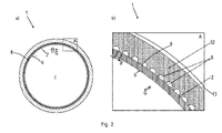
- a capillary structure is arranged in FIGS. 2a and b will be explained in detail.
- a first channel 5 is formed, through which a first medium can be conducted, so that the first medium emits a heat flow to an inner circumferential surface 6 of the inner tube 2, which then flows through the lateral surface 7 of the inner tube 2 and into the capillary structure K is transferred by means of heat conduction.
- a second channel 9 in the form of an evaporation tube is formed, through which a second medium flows, wherein the evaporation channel has a capillary structure K.
- closures 10, 11 are each end attached, which complete the second channel 9.
- the closures 10, 11 themselves may have further connections or be designed as a connection itself, in order to introduce the second medium into the second channel 9.
- FIG. 2a shows a cross-sectional view of the inventive evaporator tube 1 and FIG. 2b a corresponding magnification according to the section A from FIG. 2a
- FIG. 2 is good to see that from an interior I a not shown exhaust gas flow emits a heat flow Q ⁇ to the inner circumferential surface 6 of the inner tube 2. From this there is a heat conduction to the outer circumferential surface 8 of the inner tube 2, where then the heat flow Q ⁇ in the second channel, shown here in the form of an evaporation channel 9, passes.
- the evaporation channel 9 is, here represented by in cross section semicircular evaporation channels 9, formed.
- the evaporation channels 9 themselves are in direct contact with the outer circumferential surface 8 of the inner tube. 2
- a distance a is formed in each case between the individual evaporation channels 9, the sinter layer 12 being in direct contact with the outer jacket surface 8 of the inner tube 2 in the region of this distance.
- an outer mold 13 which is only schematically indicated here, can then be arranged on the sintering layer 12 from the outside.
- the outer mold 13 initially serves as a mold during the sintering process, wherein in particular within the scope of the invention, also between the outer mold 13 and inner tube 2, the entire second channel can be formed.
- a corresponding supply of the second medium and a discharge of the evaporated second medium then takes place via the in FIG. 1 shown connections in the closures 11, 12th
Landscapes
- Engineering & Computer Science (AREA)
- Manufacturing & Machinery (AREA)
- Mechanical Engineering (AREA)
- Chemical & Material Sciences (AREA)
- Composite Materials (AREA)
- Materials Engineering (AREA)
- Powder Metallurgy (AREA)
Applications Claiming Priority (1)
| Application Number | Priority Date | Filing Date | Title |
|---|---|---|---|
| DE102013103836.0A DE102013103836B4 (de) | 2013-04-16 | 2013-04-16 | Verfahren zum Herstellen eines Verdampferrohres |
Publications (2)
| Publication Number | Publication Date |
|---|---|
| EP2792437A1 true EP2792437A1 (fr) | 2014-10-22 |
| EP2792437B1 EP2792437B1 (fr) | 2015-11-04 |
Family
ID=50230893
Family Applications (1)
| Application Number | Title | Priority Date | Filing Date |
|---|---|---|---|
| EP14157192.7A Not-in-force EP2792437B1 (fr) | 2013-04-16 | 2014-02-28 | Procédé de fabrication d'un tube d'évaporateur |
Country Status (2)
| Country | Link |
|---|---|
| EP (1) | EP2792437B1 (fr) |
| DE (1) | DE102013103836B4 (fr) |
Cited By (1)
| Publication number | Priority date | Publication date | Assignee | Title |
|---|---|---|---|---|
| EP3095704A1 (fr) * | 2015-05-21 | 2016-11-23 | FINMECCANICA-Società per azioni | Système de récupération de chaleur, en particulier pour être utilisé sur un aéronef, à l'aide d'un circuit de fluide à deux phases |
Citations (5)
| Publication number | Priority date | Publication date | Assignee | Title |
|---|---|---|---|---|
| US3345160A (en) * | 1965-07-09 | 1967-10-03 | Carborundum Co | Method for making ducted refractory articles |
| US3751271A (en) * | 1970-05-12 | 1973-08-07 | Toyota Kk | Sintered filter having straight holes therethrough |
| WO2002044639A1 (fr) * | 2000-11-30 | 2002-06-06 | Khpt Co., Ltd | Caloduc a structure de meche frittee avec trous de type tuyaux paralleles et procede de fabrication de celui-ci |
| WO2009157611A1 (fr) * | 2008-06-23 | 2009-12-30 | Zalman Tech Co., Ltd. | Procédé de fabrication d'un évaporateur pour système de caloduc en boucle |
| DE102011103110A1 (de) * | 2011-05-25 | 2012-11-29 | Benteler Automobiltechnik Gmbh | Abgassystem mit Kreislaufwärmerohr |
-
2013
- 2013-04-16 DE DE102013103836.0A patent/DE102013103836B4/de not_active Expired - Fee Related
-
2014
- 2014-02-28 EP EP14157192.7A patent/EP2792437B1/fr not_active Not-in-force
Patent Citations (5)
| Publication number | Priority date | Publication date | Assignee | Title |
|---|---|---|---|---|
| US3345160A (en) * | 1965-07-09 | 1967-10-03 | Carborundum Co | Method for making ducted refractory articles |
| US3751271A (en) * | 1970-05-12 | 1973-08-07 | Toyota Kk | Sintered filter having straight holes therethrough |
| WO2002044639A1 (fr) * | 2000-11-30 | 2002-06-06 | Khpt Co., Ltd | Caloduc a structure de meche frittee avec trous de type tuyaux paralleles et procede de fabrication de celui-ci |
| WO2009157611A1 (fr) * | 2008-06-23 | 2009-12-30 | Zalman Tech Co., Ltd. | Procédé de fabrication d'un évaporateur pour système de caloduc en boucle |
| DE102011103110A1 (de) * | 2011-05-25 | 2012-11-29 | Benteler Automobiltechnik Gmbh | Abgassystem mit Kreislaufwärmerohr |
Cited By (2)
| Publication number | Priority date | Publication date | Assignee | Title |
|---|---|---|---|---|
| EP3095704A1 (fr) * | 2015-05-21 | 2016-11-23 | FINMECCANICA-Società per azioni | Système de récupération de chaleur, en particulier pour être utilisé sur un aéronef, à l'aide d'un circuit de fluide à deux phases |
| US10029800B2 (en) | 2015-05-21 | 2018-07-24 | Leonardo S.P.A. | Heat recovery system, in particular for use on aircraft, using a two-phase fluid circuit |
Also Published As
| Publication number | Publication date |
|---|---|
| DE102013103836A1 (de) | 2014-10-16 |
| EP2792437B1 (fr) | 2015-11-04 |
| DE102013103836B4 (de) | 2018-05-03 |
Similar Documents
| Publication | Publication Date | Title |
|---|---|---|
| EP2799805B1 (fr) | Tube d'évaporateur à disposer dans un système d'échappement et procédé de fabrication du tube d'évaporateur doté d'une structure frittée poreuse et de canaux de vapeur | |
| EP2510302B1 (fr) | Tube échangeur thermique | |
| EP2492119A2 (fr) | Accumulateur thermique latent | |
| DE112017000580T5 (de) | Additiv gefertigte rotoren für kompressoren und expander querverweis auf verwandte anmeldungen | |
| DE602006000885T2 (de) | Rotor für eine elektrische Maschine | |
| DE102008060116A1 (de) | Verfahren zur Herstellung einer Lageranordnung und Lageranordnung | |
| DE102013226664A1 (de) | Turbinenläufer und Verfahren zur Herstellung des Turbinenläufers | |
| DE102013226732A1 (de) | Adsorberstruktur | |
| DE102010011486A1 (de) | Rotor für eine Ladeeinrichtung | |
| EP2314971B1 (fr) | Accumulateur thermique doté d'une alimentation en énergie pour un rendement de puissance stable dans le temps et régulier ainsi que son procédé | |
| DE102012217560A1 (de) | Turbinenläufer mit Hülsenzwischenstück, Abgasturbolader und ein Verfahren zur Herstellung des Turbinenläufers | |
| EP2792437B1 (fr) | Procédé de fabrication d'un tube d'évaporateur | |
| EP2404368A2 (fr) | Rotor pour moteur électrique et procédé de fabrication d'un tel rotor | |
| EP3054259A1 (fr) | Procede de fabrication d'un echangeur thermique | |
| DE102019124788A1 (de) | Verfahren zum Betreiben einer Antriebseinrichtung für ein Kraftfahrzeug sowie entsprechende Antriebseinrichtung | |
| WO2017016646A1 (fr) | Conduit de transfert de chaleur, réservoir thermique et procédé de fabrication d'un conduit de transfert de chaleur | |
| DE102011103109A1 (de) | Abgassystem mit Wärmespeicher | |
| WO2017016647A1 (fr) | Tube de transfert de chaleur, accumulateur de chaleur et procédé de production d'un tube de transfert de chaleur | |
| WO2016055233A1 (fr) | Corps de chauffe pour bougie de préchauffage pouvant être allumée électriquement, comprenant une charge de chauffe comprimée axialement, et procédé de fabrication correspondant | |
| EP2527761A2 (fr) | Dispositif de transfert thermique | |
| AT523430B1 (de) | Verfahren zur Herstellung eines Wärmerohres | |
| DE102012205496A1 (de) | Thermisch isoliertes Leitungselement und Verfahren zu dessen Herstellung | |
| EP2950031B1 (fr) | Échangeur thermique de gaz d'échappement en acier duplex | |
| DE102011121510A1 (de) | Hitzeschild | |
| DE102012211481A1 (de) | Verfahren und Vorrichtung zum Herstellen eines Bauteils |
Legal Events
| Date | Code | Title | Description |
|---|---|---|---|
| PUAI | Public reference made under article 153(3) epc to a published international application that has entered the european phase |
Free format text: ORIGINAL CODE: 0009012 |
|
| 17P | Request for examination filed |
Effective date: 20140722 |
|
| AK | Designated contracting states |
Kind code of ref document: A1 Designated state(s): AL AT BE BG CH CY CZ DE DK EE ES FI FR GB GR HR HU IE IS IT LI LT LU LV MC MK MT NL NO PL PT RO RS SE SI SK SM TR |
|
| AX | Request for extension of the european patent |
Extension state: BA ME |
|
| GRAP | Despatch of communication of intention to grant a patent |
Free format text: ORIGINAL CODE: EPIDOSNIGR1 |
|
| INTG | Intention to grant announced |
Effective date: 20150715 |
|
| GRAS | Grant fee paid |
Free format text: ORIGINAL CODE: EPIDOSNIGR3 |
|
| GRAA | (expected) grant |
Free format text: ORIGINAL CODE: 0009210 |
|
| AK | Designated contracting states |
Kind code of ref document: B1 Designated state(s): AL AT BE BG CH CY CZ DE DK EE ES FI FR GB GR HR HU IE IS IT LI LT LU LV MC MK MT NL NO PL PT RO RS SE SI SK SM TR |
|
| REG | Reference to a national code |
Ref country code: GB Ref legal event code: FG4D Free format text: NOT ENGLISH |
|
| REG | Reference to a national code |
Ref country code: CH Ref legal event code: EP |
|
| REG | Reference to a national code |
Ref country code: AT Ref legal event code: REF Ref document number: 758849 Country of ref document: AT Kind code of ref document: T Effective date: 20151115 |
|
| REG | Reference to a national code |
Ref country code: IE Ref legal event code: FG4D Free format text: LANGUAGE OF EP DOCUMENT: GERMAN |
|
| REG | Reference to a national code |
Ref country code: DE Ref legal event code: R096 Ref document number: 502014000175 Country of ref document: DE |
|
| REG | Reference to a national code |
Ref country code: FR Ref legal event code: PLFP Year of fee payment: 3 |
|
| REG | Reference to a national code |
Ref country code: NL Ref legal event code: MP Effective date: 20151104 |
|
| REG | Reference to a national code |
Ref country code: LT Ref legal event code: MG4D |
|
| PG25 | Lapsed in a contracting state [announced via postgrant information from national office to epo] |
Ref country code: NL Free format text: LAPSE BECAUSE OF FAILURE TO SUBMIT A TRANSLATION OF THE DESCRIPTION OR TO PAY THE FEE WITHIN THE PRESCRIBED TIME-LIMIT Effective date: 20151104 Ref country code: NO Free format text: LAPSE BECAUSE OF FAILURE TO SUBMIT A TRANSLATION OF THE DESCRIPTION OR TO PAY THE FEE WITHIN THE PRESCRIBED TIME-LIMIT Effective date: 20160204 Ref country code: IS Free format text: LAPSE BECAUSE OF FAILURE TO SUBMIT A TRANSLATION OF THE DESCRIPTION OR TO PAY THE FEE WITHIN THE PRESCRIBED TIME-LIMIT Effective date: 20160304 Ref country code: ES Free format text: LAPSE BECAUSE OF FAILURE TO SUBMIT A TRANSLATION OF THE DESCRIPTION OR TO PAY THE FEE WITHIN THE PRESCRIBED TIME-LIMIT Effective date: 20151104 Ref country code: LT Free format text: LAPSE BECAUSE OF FAILURE TO SUBMIT A TRANSLATION OF THE DESCRIPTION OR TO PAY THE FEE WITHIN THE PRESCRIBED TIME-LIMIT Effective date: 20151104 Ref country code: IT Free format text: LAPSE BECAUSE OF FAILURE TO SUBMIT A TRANSLATION OF THE DESCRIPTION OR TO PAY THE FEE WITHIN THE PRESCRIBED TIME-LIMIT Effective date: 20151104 Ref country code: HR Free format text: LAPSE BECAUSE OF FAILURE TO SUBMIT A TRANSLATION OF THE DESCRIPTION OR TO PAY THE FEE WITHIN THE PRESCRIBED TIME-LIMIT Effective date: 20151104 |
|
| PG25 | Lapsed in a contracting state [announced via postgrant information from national office to epo] |
Ref country code: SE Free format text: LAPSE BECAUSE OF FAILURE TO SUBMIT A TRANSLATION OF THE DESCRIPTION OR TO PAY THE FEE WITHIN THE PRESCRIBED TIME-LIMIT Effective date: 20151104 Ref country code: FI Free format text: LAPSE BECAUSE OF FAILURE TO SUBMIT A TRANSLATION OF THE DESCRIPTION OR TO PAY THE FEE WITHIN THE PRESCRIBED TIME-LIMIT Effective date: 20151104 Ref country code: PL Free format text: LAPSE BECAUSE OF FAILURE TO SUBMIT A TRANSLATION OF THE DESCRIPTION OR TO PAY THE FEE WITHIN THE PRESCRIBED TIME-LIMIT Effective date: 20151104 Ref country code: GR Free format text: LAPSE BECAUSE OF FAILURE TO SUBMIT A TRANSLATION OF THE DESCRIPTION OR TO PAY THE FEE WITHIN THE PRESCRIBED TIME-LIMIT Effective date: 20160205 Ref country code: PT Free format text: LAPSE BECAUSE OF FAILURE TO SUBMIT A TRANSLATION OF THE DESCRIPTION OR TO PAY THE FEE WITHIN THE PRESCRIBED TIME-LIMIT Effective date: 20160304 Ref country code: RS Free format text: LAPSE BECAUSE OF FAILURE TO SUBMIT A TRANSLATION OF THE DESCRIPTION OR TO PAY THE FEE WITHIN THE PRESCRIBED TIME-LIMIT Effective date: 20151104 Ref country code: LV Free format text: LAPSE BECAUSE OF FAILURE TO SUBMIT A TRANSLATION OF THE DESCRIPTION OR TO PAY THE FEE WITHIN THE PRESCRIBED TIME-LIMIT Effective date: 20151104 Ref country code: BE Free format text: LAPSE BECAUSE OF NON-PAYMENT OF DUE FEES Effective date: 20160229 |
|
| REG | Reference to a national code |
Ref country code: DE Ref legal event code: R097 Ref document number: 502014000175 Country of ref document: DE |
|
| PG25 | Lapsed in a contracting state [announced via postgrant information from national office to epo] |
Ref country code: SM Free format text: LAPSE BECAUSE OF FAILURE TO SUBMIT A TRANSLATION OF THE DESCRIPTION OR TO PAY THE FEE WITHIN THE PRESCRIBED TIME-LIMIT Effective date: 20151104 Ref country code: SK Free format text: LAPSE BECAUSE OF FAILURE TO SUBMIT A TRANSLATION OF THE DESCRIPTION OR TO PAY THE FEE WITHIN THE PRESCRIBED TIME-LIMIT Effective date: 20151104 Ref country code: DK Free format text: LAPSE BECAUSE OF FAILURE TO SUBMIT A TRANSLATION OF THE DESCRIPTION OR TO PAY THE FEE WITHIN THE PRESCRIBED TIME-LIMIT Effective date: 20151104 Ref country code: EE Free format text: LAPSE BECAUSE OF FAILURE TO SUBMIT A TRANSLATION OF THE DESCRIPTION OR TO PAY THE FEE WITHIN THE PRESCRIBED TIME-LIMIT Effective date: 20151104 Ref country code: RO Free format text: LAPSE BECAUSE OF FAILURE TO SUBMIT A TRANSLATION OF THE DESCRIPTION OR TO PAY THE FEE WITHIN THE PRESCRIBED TIME-LIMIT Effective date: 20151104 |
|
| PLBE | No opposition filed within time limit |
Free format text: ORIGINAL CODE: 0009261 |
|
| STAA | Information on the status of an ep patent application or granted ep patent |
Free format text: STATUS: NO OPPOSITION FILED WITHIN TIME LIMIT |
|
| PG25 | Lapsed in a contracting state [announced via postgrant information from national office to epo] |
Ref country code: MC Free format text: LAPSE BECAUSE OF FAILURE TO SUBMIT A TRANSLATION OF THE DESCRIPTION OR TO PAY THE FEE WITHIN THE PRESCRIBED TIME-LIMIT Effective date: 20151104 Ref country code: LU Free format text: LAPSE BECAUSE OF FAILURE TO SUBMIT A TRANSLATION OF THE DESCRIPTION OR TO PAY THE FEE WITHIN THE PRESCRIBED TIME-LIMIT Effective date: 20160228 |
|
| 26N | No opposition filed |
Effective date: 20160805 |
|
| PG25 | Lapsed in a contracting state [announced via postgrant information from national office to epo] |
Ref country code: SI Free format text: LAPSE BECAUSE OF FAILURE TO SUBMIT A TRANSLATION OF THE DESCRIPTION OR TO PAY THE FEE WITHIN THE PRESCRIBED TIME-LIMIT Effective date: 20151104 |
|
| REG | Reference to a national code |
Ref country code: IE Ref legal event code: MM4A |
|
| PG25 | Lapsed in a contracting state [announced via postgrant information from national office to epo] |
Ref country code: IE Free format text: LAPSE BECAUSE OF NON-PAYMENT OF DUE FEES Effective date: 20160228 |
|
| REG | Reference to a national code |
Ref country code: FR Ref legal event code: PLFP Year of fee payment: 4 |
|
| PG25 | Lapsed in a contracting state [announced via postgrant information from national office to epo] |
Ref country code: MT Free format text: LAPSE BECAUSE OF FAILURE TO SUBMIT A TRANSLATION OF THE DESCRIPTION OR TO PAY THE FEE WITHIN THE PRESCRIBED TIME-LIMIT Effective date: 20151104 |
|
| REG | Reference to a national code |
Ref country code: CH Ref legal event code: PL |
|
| PG25 | Lapsed in a contracting state [announced via postgrant information from national office to epo] |
Ref country code: LI Free format text: LAPSE BECAUSE OF NON-PAYMENT OF DUE FEES Effective date: 20170228 Ref country code: CH Free format text: LAPSE BECAUSE OF NON-PAYMENT OF DUE FEES Effective date: 20170228 |
|
| REG | Reference to a national code |
Ref country code: FR Ref legal event code: PLFP Year of fee payment: 5 |
|
| PGFP | Annual fee paid to national office [announced via postgrant information from national office to epo] |
Ref country code: GB Payment date: 20180216 Year of fee payment: 5 Ref country code: CZ Payment date: 20180227 Year of fee payment: 5 |
|
| PG25 | Lapsed in a contracting state [announced via postgrant information from national office to epo] |
Ref country code: HU Free format text: LAPSE BECAUSE OF FAILURE TO SUBMIT A TRANSLATION OF THE DESCRIPTION OR TO PAY THE FEE WITHIN THE PRESCRIBED TIME-LIMIT; INVALID AB INITIO Effective date: 20140228 |
|
| PGFP | Annual fee paid to national office [announced via postgrant information from national office to epo] |
Ref country code: FR Payment date: 20180223 Year of fee payment: 5 |
|
| PG25 | Lapsed in a contracting state [announced via postgrant information from national office to epo] |
Ref country code: MK Free format text: LAPSE BECAUSE OF FAILURE TO SUBMIT A TRANSLATION OF THE DESCRIPTION OR TO PAY THE FEE WITHIN THE PRESCRIBED TIME-LIMIT Effective date: 20151104 Ref country code: CY Free format text: LAPSE BECAUSE OF FAILURE TO SUBMIT A TRANSLATION OF THE DESCRIPTION OR TO PAY THE FEE WITHIN THE PRESCRIBED TIME-LIMIT Effective date: 20151104 |
|
| PG25 | Lapsed in a contracting state [announced via postgrant information from national office to epo] |
Ref country code: BG Free format text: LAPSE BECAUSE OF FAILURE TO SUBMIT A TRANSLATION OF THE DESCRIPTION OR TO PAY THE FEE WITHIN THE PRESCRIBED TIME-LIMIT Effective date: 20151104 |
|
| PG25 | Lapsed in a contracting state [announced via postgrant information from national office to epo] |
Ref country code: AL Free format text: LAPSE BECAUSE OF FAILURE TO SUBMIT A TRANSLATION OF THE DESCRIPTION OR TO PAY THE FEE WITHIN THE PRESCRIBED TIME-LIMIT Effective date: 20151104 Ref country code: TR Free format text: LAPSE BECAUSE OF FAILURE TO SUBMIT A TRANSLATION OF THE DESCRIPTION OR TO PAY THE FEE WITHIN THE PRESCRIBED TIME-LIMIT Effective date: 20151104 |
|
| PGFP | Annual fee paid to national office [announced via postgrant information from national office to epo] |
Ref country code: DE Payment date: 20190227 Year of fee payment: 6 |
|
| GBPC | Gb: european patent ceased through non-payment of renewal fee |
Effective date: 20190228 |
|
| PG25 | Lapsed in a contracting state [announced via postgrant information from national office to epo] |
Ref country code: CZ Free format text: LAPSE BECAUSE OF NON-PAYMENT OF DUE FEES Effective date: 20190228 |
|
| PG25 | Lapsed in a contracting state [announced via postgrant information from national office to epo] |
Ref country code: GB Free format text: LAPSE BECAUSE OF NON-PAYMENT OF DUE FEES Effective date: 20190228 |
|
| PG25 | Lapsed in a contracting state [announced via postgrant information from national office to epo] |
Ref country code: FR Free format text: LAPSE BECAUSE OF NON-PAYMENT OF DUE FEES Effective date: 20190228 |
|
| REG | Reference to a national code |
Ref country code: AT Ref legal event code: MM01 Ref document number: 758849 Country of ref document: AT Kind code of ref document: T Effective date: 20190228 |
|
| PG25 | Lapsed in a contracting state [announced via postgrant information from national office to epo] |
Ref country code: AT Free format text: LAPSE BECAUSE OF NON-PAYMENT OF DUE FEES Effective date: 20190228 |
|
| REG | Reference to a national code |
Ref country code: DE Ref legal event code: R119 Ref document number: 502014000175 Country of ref document: DE |
|
| PG25 | Lapsed in a contracting state [announced via postgrant information from national office to epo] |
Ref country code: DE Free format text: LAPSE BECAUSE OF NON-PAYMENT OF DUE FEES Effective date: 20200901 |