EP2792960B1 - Verfahren zur Überwachung einer Wärmetauscheranordnung und Wärmetauscherüberwachungssystem - Google Patents
Verfahren zur Überwachung einer Wärmetauscheranordnung und Wärmetauscherüberwachungssystem Download PDFInfo
- Publication number
- EP2792960B1 EP2792960B1 EP14164045.8A EP14164045A EP2792960B1 EP 2792960 B1 EP2792960 B1 EP 2792960B1 EP 14164045 A EP14164045 A EP 14164045A EP 2792960 B1 EP2792960 B1 EP 2792960B1
- Authority
- EP
- European Patent Office
- Prior art keywords
- heat exchanger
- air fan
- ram air
- exchanger arrangement
- controller
- Prior art date
- Legal status (The legal status is an assumption and is not a legal conclusion. Google has not performed a legal analysis and makes no representation as to the accuracy of the status listed.)
- Active
Links
Images
Classifications
-
- F—MECHANICAL ENGINEERING; LIGHTING; HEATING; WEAPONS; BLASTING
- F28—HEAT EXCHANGE IN GENERAL
- F28F—DETAILS OF HEAT-EXCHANGE AND HEAT-TRANSFER APPARATUS, OF GENERAL APPLICATION
- F28F27/00—Control arrangements or safety devices specially adapted for heat-exchange or heat-transfer apparatus
-
- B—PERFORMING OPERATIONS; TRANSPORTING
- B64—AIRCRAFT; AVIATION; COSMONAUTICS
- B64D—EQUIPMENT FOR FITTING IN OR TO AIRCRAFT; FLIGHT SUITS; PARACHUTES; ARRANGEMENT OR MOUNTING OF POWER PLANTS OR PROPULSION TRANSMISSIONS IN AIRCRAFT
- B64D13/00—Arrangements or adaptations of air-treatment apparatus for aircraft crew or passengers, or freight space
- B64D13/06—Arrangements or adaptations of air-treatment apparatus for aircraft crew or passengers, or freight space the air being conditioned
- B64D13/08—Arrangements or adaptations of air-treatment apparatus for aircraft crew or passengers, or freight space the air being conditioned the air being heated or cooled
-
- B—PERFORMING OPERATIONS; TRANSPORTING
- B64—AIRCRAFT; AVIATION; COSMONAUTICS
- B64D—EQUIPMENT FOR FITTING IN OR TO AIRCRAFT; FLIGHT SUITS; PARACHUTES; ARRANGEMENT OR MOUNTING OF POWER PLANTS OR PROPULSION TRANSMISSIONS IN AIRCRAFT
- B64D13/00—Arrangements or adaptations of air-treatment apparatus for aircraft crew or passengers, or freight space
- B64D13/06—Arrangements or adaptations of air-treatment apparatus for aircraft crew or passengers, or freight space the air being conditioned
-
- B—PERFORMING OPERATIONS; TRANSPORTING
- B64—AIRCRAFT; AVIATION; COSMONAUTICS
- B64D—EQUIPMENT FOR FITTING IN OR TO AIRCRAFT; FLIGHT SUITS; PARACHUTES; ARRANGEMENT OR MOUNTING OF POWER PLANTS OR PROPULSION TRANSMISSIONS IN AIRCRAFT
- B64D13/00—Arrangements or adaptations of air-treatment apparatus for aircraft crew or passengers, or freight space
- B64D13/06—Arrangements or adaptations of air-treatment apparatus for aircraft crew or passengers, or freight space the air being conditioned
- B64D2013/0603—Environmental Control Systems
- B64D2013/0618—Environmental Control Systems with arrangements for reducing or managing bleed air, using another air source, e.g. ram air
-
- B—PERFORMING OPERATIONS; TRANSPORTING
- B64—AIRCRAFT; AVIATION; COSMONAUTICS
- B64D—EQUIPMENT FOR FITTING IN OR TO AIRCRAFT; FLIGHT SUITS; PARACHUTES; ARRANGEMENT OR MOUNTING OF POWER PLANTS OR PROPULSION TRANSMISSIONS IN AIRCRAFT
- B64D13/00—Arrangements or adaptations of air-treatment apparatus for aircraft crew or passengers, or freight space
- B64D13/06—Arrangements or adaptations of air-treatment apparatus for aircraft crew or passengers, or freight space the air being conditioned
- B64D2013/0603—Environmental Control Systems
- B64D2013/0644—Environmental Control Systems including electric motors or generators
-
- Y—GENERAL TAGGING OF NEW TECHNOLOGICAL DEVELOPMENTS; GENERAL TAGGING OF CROSS-SECTIONAL TECHNOLOGIES SPANNING OVER SEVERAL SECTIONS OF THE IPC; TECHNICAL SUBJECTS COVERED BY FORMER USPC CROSS-REFERENCE ART COLLECTIONS [XRACs] AND DIGESTS
- Y02—TECHNOLOGIES OR APPLICATIONS FOR MITIGATION OR ADAPTATION AGAINST CLIMATE CHANGE
- Y02T—CLIMATE CHANGE MITIGATION TECHNOLOGIES RELATED TO TRANSPORTATION
- Y02T50/00—Aeronautics or air transport
- Y02T50/50—On board measures aiming to increase energy efficiency
Definitions
- the present invention relates to heat exchanger arrangements, and more particularly to a method of monitoring a heat exchanger arrangement for excessive pressure drops that may lead to a stall condition.
- the prior art is illustrated by document JP-A-2010223494 .
- Motor assemblies utilizing ram air flow are employed in a variety of applications, with one such application being an aircraft.
- the ram air flow in an aircraft may serve various purposes, such as in cooling systems for the aircraft.
- the ram air flow may be utilized to remove heat from various aircraft systems and/or be used to condition aircraft cabin air through a heat exchanger arrangement.
- the movement of the aircraft creates a sufficient source of ram air flow which can be used for the purposes described above.
- a ram air fan When the aircraft is on the ground or is operating at low speeds, however, a ram air fan is typically utilized to supply air flow to the cooling systems. Over time, contamination from ambient air will increase the pressure drop of the heat exchanger arrangement, thereby reducing flow through the ram air fan and heat exchangers. Significant heat exchanger contamination may reduce the airflow to the extent that the ram air fan operates in an unstable operating mode, such as a stall condition, which may cause excessive blade stress resulting in a failure of the ram air fan.
- a method of monitoring a heat exchanger arrangement includes detecting a rotational speed of a ram air fan configured to draw air through the heat exchanger arrangement.
- the method also includes detecting a power input to a motor driving the ram air fan to maintain a commanded rotational speed of the ram air fan.
- the method further includes comparing the power input detected to a predetermined power limit for the commanded rotational speed.
- the method yet further includes decreasing the rotational speed of the ram air fan with a controller if the power input detected exceeds the predetermined power limit, wherein the controller is programmed with a plurality of predetermined power limits corresponding to a plurality of rotational speeds of the ram air fan.
- a heat exchanger arrangement monitoring system includes a ram air fan configured to draw air through a heat exchanger arrangement. Also included is a motor for powering the ram air fan. Further included is a controller in operative communication with the motor and configured to monitor a rotational speed of the ram air fan and a power required to drive the ram air fan, wherein the controller compares the power to a predetermined power limit and is programmed with a plurality of predetermined power limits corresponding to a plurality of rotational speeds of the ram air fan and configured to decrease the rotational speed of the ram air fan upon the power exceeding the predetermined power limit.
- the heat exchanger arrangement monitoring system may be located on an aircraft and include an air conditioning system having a heat exchanger arrangement for conditioning a main flow.
- a ram air fan configured to draw the main flow during relatively low flow conditions of the main flow.
- a motor for powering the ram air fan.
- a controller in operative communication with the motor and configured to decrease a rotational speed of the ram air fan and a power required to drive the ram air fan upon detection of the power required exceeding a predetermined power limit at a commanded rotational speed of the ram air fan.
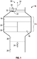
- the heat exchanger arrangement monitoring system 10 may be used in conjunction with an assembly or system of a vehicle, such as an aircraft, however, it is contemplated that other vehicles may benefit from the embodiments described herein.
- the heat exchanger arrangement monitoring system 10 includes a motor 12 and a heat exchanger arrangement 14 comprising at least one heat exchanger, such as a primary heat exchanger 16 and a secondary heat exchanger 18.
- the heat exchanger arrangement 14 is part of an air conditioning system and works in conjunction with one or more air conditioning packs 20.
- the motor 12 may be employed to drive a variety of contemplated loads and in the exemplary embodiment, the load is a ram air fan 22.
- the heat exchanger arrangement 14 is configured to ingest a fluid, such as a main flow 24 of air.
- the main flow 24 may be sourced from ambient air through a conduit 26 and is drawn into the heat exchanger arrangement 14 through a heat exchanger inlet 28 via a pressure drop across the heat exchanger arrangement 14. Subsequently, the main flow 24 is expelled via a heat exchanger outlet 30.
- there are times of operation when drawing of the main flow 24 is required by the ram air fan 22 during conditions when the natural airflow into the heat exchanger arrangement 14 is not sufficient to meet the requirements of the aircraft. Such an instance occurs while the aircraft is not in flight.
- the ram air fan 22 is operably connected to the motor 12 via at least one shaft 32.
- the motor 12 is controlled by a controller 34 disposed relatively adjacent to the motor 12, but remote locations of the controller 34 are contemplated. Regardless of the precise positioning of the controller 34, the controller 34 is in operative communication with the motor 12.
- the operative communication between the motor 12 and the controller 34 allows the controller 34 to monitor a motor power required to drive the ram air fan 22 at a commanded rotational speed.
- the controller 34 is programmed with a specified power level that the motor 12 should exert under normal operating conditions at each commanded rotational speed of the ram air fan 22.
- the controller 34 is programmed with at least one, but typically a plurality of normal power levels that correspond to a plurality of rotational speeds of the ram air fan 22 at given ambient conditions, such as temperature and pressure.
- the heat exchanger arrangement monitoring system 10 is configured to indirectly monitor the pressure drop of the main flow 24 across the heat exchanger arrangement 14.
- One cause of increased pressure drop across the heat exchanger arrangement 14 relates to contamination from ambient air. Specifically, particles such as dirt and the like adhere to components of the heat exchanger arrangement 14 and produce excessive pressure drop therein. Contamination leads to an increase in motor power required to maintain a given commanded rotational speed of the ram air fan 22.
- the increase in required power is detected by the controller 34 and compared to a predetermined power limit for a particular commanded rotational speed of the ram air fan 22.
- the predetermined power limit corresponds to an increase of required power of about 10%.
- the predetermined power limit is about 110% of the normal power level at a given commanded rotational speed of the ram air fan 22.
- the controller 34 is configured to perform one or more corrective actions to prevent operation of the ram air fan 22 in an unstable operating mode, such as a stall condition, which may lead to operation failure of the ram air fan 22.
- the controller 34 reduces the rotational speed of the ram air fan 22 by decreasing the power transferred from the motor 12. Additionally, a maintenance message may be initiated and delivered to alert system operators that cleaning of the heat exchanger arrangement 14 is required to remove contaminants from the heat exchanger arrangement 14 that likely caused the corrective action.
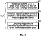
- a method of monitoring a heat exchanger arrangement 100 is also provided, as illustrated in FIG. 2 and with reference to Fig. 1 .
- the heat exchanger arrangement monitoring system 10 has been previously described and specific structural components need not be described in further detail.
- the method of monitoring a heat exchanger arrangement 100 includes detecting 102 a rotational speed of the ram air fan 22 that is configured to draw the main flow 24 through the heat exchanger arrangement 14.
- a power input is detected 104 from the motor 12 that is required to maintain a commanded rotational speed of the ram air fan 22.
- the method 100 also includes comparing 106 the power input detected 104 to a predetermined power limit for the commanded rotational speed.
Landscapes
- Engineering & Computer Science (AREA)
- Health & Medical Sciences (AREA)
- General Health & Medical Sciences (AREA)
- Pulmonology (AREA)
- Aviation & Aerospace Engineering (AREA)
- Physics & Mathematics (AREA)
- Thermal Sciences (AREA)
- Mechanical Engineering (AREA)
- General Engineering & Computer Science (AREA)
- Cooling Or The Like Of Electrical Apparatus (AREA)
- Air-Conditioning For Vehicles (AREA)
Claims (10)
- Verfahren zur Überwachung des Druckabfalls einer Wärmetauscheranordnung (14), umfassend:Erfassen einer Drehzahl eines Stauluftgebläses (22), das konfiguriert ist, um Luft durch die Wärmetauscheranordnung (14) zu ziehen;Erfassen eines Leistungseingangs in einen Motor (12), der das Stauluftgebläse (22) antreibt, um eine befohlene Drehzahl des Stauluftgebläses (22) beizubehalten;Vergleichen des erfassten Leistungseingangs mit einem vorbestimmten Leistungsschwellenwert für die befohlene Drehzahl; wobei das Verfahren durch Folgendes gekennzeichnet ist:Verringern der Drehgeschwindigkeit des Stauluftgebläses (22) mit einer Steuerung (34), falls der erfasste Leistungseingang den vorbestimmten Leistungsschwellenwert übersteigt, wobei die Steuerung (34) mit einer Vielzahl von vorbestimmten Leistungsschwellenwerten programmiert ist, die einer Vielzahl von Drehzahlen des Stauluftgebläses (22) entspricht.
- Verfahren nach Anspruch 1, wobei der vorbestimmte Leistungsschwellenwert etwa 110 % eines normalen Leistungseingangs umfasst.
- Verfahren nach Anspruch 1 oder 2, das ferner das Erzeugen einer Wartungsnachricht umfasst, wenn der erfasste Leistungseingang den vorbestimmten Leistungsschwellenwert übersteigt.
- Verfahren nach Anspruch 3, das ferner das Reinigen der Wärmetauscheranordnung von Verunreinigungen bei der Erzeugung einer Wartungsnachricht umfasst.
- Verfahren nach einem der vorhergehenden Ansprüche, wobei das Verfahren an einer Wärmetauscheranordnung für ein Luftfahrzeug (14) durchgeführt wird.
- Verfahren nach einem der vorhergehenden Ansprüche, das ferner das Durchführen des Verfahrens bei einem niedrigen Strömungszustand umfasst.
- Wärmetauscherüberwachungssystem (10), umfassend:ein Stauluftgebläse (22), das konfiguriert ist, um Luft durch die Wärmetauscheranordnung (14) zu ziehen;einen Motor (12) zum Antreiben des Stauluftgebläses (22); undeine Steuerung (34) in Wirkverbindung mit dem Motor (12) und konfiguriert, um eine Drehzahl des Stauluftgebläses (22) und eine Leistung zu überwachen, die erforderlich ist, um das Stauluftgebläse (22) anzutreiben, wobei die Steuerung (34) konfiguriert ist, um die Leistung mit einem vorbestimmten Leistungsschwellenwert zu vergleichen, dadurch gekennzeichnet, dassdie Steuerung (34) mit einer Vielzahl von vorbestimmten Leistungsschwellenwerten programmiert ist, die einer Vielzahl von Drehzahlen des Stauluftgebläses (22) entspricht, und die Steuerung (34) konfiguriert ist, um die Drehzahl des Stauluftgebläses (22) zu verringern, wenn die Leistung den vorbestimmten Leistungsschwellenwert übersteigt.
- Wärmetauscherüberwachungssystem (10) nach Anspruch 7, wobei der vorbestimmte Leistungsschwellenwert etwa 110 % eines normalen Leistungseingangs umfasst.
- Wärmetauscherüberwachungssystem (10) nach Anspruch 7 oder 8, wobei das Wärmetauscherüberwachungssystem an einem Luftfahrzeug angeordnet ist.
- Wärmetauscherüberwachungssystem (10) nach einem der Ansprüche 7 bis 9, wobei die Steuerung (34) konfiguriert ist, um die durch den Motor (12) ausgeübte Leistung zu steuern, um das Stauluftgebläse (22) anzutreiben.
Applications Claiming Priority (1)
| Application Number | Priority Date | Filing Date | Title |
|---|---|---|---|
| US13/863,718 US9784508B2 (en) | 2013-04-16 | 2013-04-16 | Method of monitoring a heat exchanger arrangement and ram air fan in an aircraft to prevent stall conditions |
Publications (2)
| Publication Number | Publication Date |
|---|---|
| EP2792960A1 EP2792960A1 (de) | 2014-10-22 |
| EP2792960B1 true EP2792960B1 (de) | 2017-08-23 |
Family
ID=50473107
Family Applications (1)
| Application Number | Title | Priority Date | Filing Date |
|---|---|---|---|
| EP14164045.8A Active EP2792960B1 (de) | 2013-04-16 | 2014-04-09 | Verfahren zur Überwachung einer Wärmetauscheranordnung und Wärmetauscherüberwachungssystem |
Country Status (2)
| Country | Link |
|---|---|
| US (1) | US9784508B2 (de) |
| EP (1) | EP2792960B1 (de) |
Families Citing this family (6)
| Publication number | Priority date | Publication date | Assignee | Title |
|---|---|---|---|---|
| TWI540262B (zh) * | 2013-08-14 | 2016-07-01 | 緯創資通股份有限公司 | 風扇控制系統及控制風扇轉速之方法 |
| US9988153B2 (en) | 2015-07-13 | 2018-06-05 | Hamilton Sundstrand Space Systems | RAF bit for surge detection |
| US10346585B2 (en) | 2016-02-22 | 2019-07-09 | Hamilton Sundstrand Corporation | Method of predicting heat exchanger blockage via ram air fan surge margin |
| US10690366B2 (en) * | 2018-03-19 | 2020-06-23 | Hamilton Sundstrand Corporation | Heat exchanger blockage detection |
| CN113790517B (zh) * | 2021-08-13 | 2022-11-08 | 珠海格力电器股份有限公司 | Ptc加热器功率衰减补偿方法、电子设备及存储介质 |
| US12595065B2 (en) * | 2022-05-02 | 2026-04-07 | Hamilton Sundstrand Corporation | 100% ambient air environmental control system |
Family Cites Families (12)
| Publication number | Priority date | Publication date | Assignee | Title |
|---|---|---|---|---|
| US3326109A (en) * | 1964-03-11 | 1967-06-20 | Bristol Siddeley Engines Ltd | Air conditioning systems for aircraft |
| JPH05332590A (ja) | 1992-05-29 | 1993-12-14 | Hitachi Ltd | 空気調和装置 |
| JP3748964B2 (ja) | 1996-11-29 | 2006-02-22 | 三洋電機株式会社 | 空気調和機 |
| AU2002350428A1 (en) * | 2001-11-23 | 2003-06-10 | Danfoss Drives A/S | Frequency converter for different mains voltages |
| ITTO20040050A1 (it) * | 2004-02-03 | 2004-05-03 | Agusta Spa | Dispositivo indicatore di un margine di potenza residua di motori a turbina di velivoli |
| US7261762B2 (en) * | 2004-05-06 | 2007-08-28 | Carrier Corporation | Technique for detecting and predicting air filter condition |
| US20100242506A1 (en) * | 2006-05-22 | 2010-09-30 | Universal Nolin Company Llc | Evaporator fan motor control in a refrigerated merchandiser |
| WO2008095129A2 (en) * | 2007-01-31 | 2008-08-07 | Turbodyne Technologies, Inc. | Generation and management of mass air flow |
| US8321118B2 (en) * | 2008-12-23 | 2012-11-27 | Honeywell International Inc. | Operations support systems and methods with power assurance |
| JP5306007B2 (ja) | 2009-03-23 | 2013-10-02 | 三菱電機株式会社 | 空気調和機 |
| JP2011249522A (ja) * | 2010-05-26 | 2011-12-08 | Fujitsu Ltd | 判定装置、及び、判定方法 |
| US8493221B2 (en) * | 2010-06-24 | 2013-07-23 | International Business Machines Corporation | Filter fouling detection using comparative temperature rise analysis |
-
2013
- 2013-04-16 US US13/863,718 patent/US9784508B2/en active Active
-
2014
- 2014-04-09 EP EP14164045.8A patent/EP2792960B1/de active Active
Non-Patent Citations (1)
| Title |
|---|
| None * |
Also Published As
| Publication number | Publication date |
|---|---|
| US20140305610A1 (en) | 2014-10-16 |
| US9784508B2 (en) | 2017-10-10 |
| EP2792960A1 (de) | 2014-10-22 |
Similar Documents
| Publication | Publication Date | Title |
|---|---|---|
| EP2792960B1 (de) | Verfahren zur Überwachung einer Wärmetauscheranordnung und Wärmetauscherüberwachungssystem | |
| EP3539874B1 (de) | Wärmetauscherblockierungsdetektion zur verhinderung von stauluftventilatorstössen | |
| CN105940221B (zh) | 用于轨道车辆的压缩机系统和具有安全的紧急运行的压缩机系统的运行方法 | |
| EP3266709B1 (de) | Lagerüberwachungssystem für eine luftkreislaufmaschine und verfahren zur überwachung | |
| EP2939926B1 (de) | Flugzeugklimatisierungssystem und -verfahren | |
| US8779698B2 (en) | Automatic variable speed motor drive bypass | |
| US9832910B2 (en) | Ram air fan and power electronics cooling systems | |
| EP2939927A1 (de) | Flugzeugumgebungskonditionierungssystem und -verfahren | |
| US11668534B2 (en) | Fan array fault response control system | |
| EP3118459B1 (de) | Stauluft-ventilator-anordnung mit pumpgrenzerkennung | |
| US9126687B2 (en) | Environmental control system having parallel compressors and method of controllably operating | |
| EP3045697B1 (de) | Kühlluftzufuhrsteuerungssystem für luftkreislaufmaschine | |
| US20140320163A1 (en) | Method for monitoring a pump | |
| US9528718B2 (en) | HVAC motor load balancing | |
| JP2008247123A (ja) | ファン制御装置 | |
| EP3734251B1 (de) | Verfahren zur überwachung einer luftzyklusmaschine eines flugzeugs | |
| EP4563794A1 (de) | Adaptive maschinenlernsteuerungen für eine luft- und raumfahrtturbomaschine mit gesundheitsüberwachungsfähigkeit | |
| US20180180053A1 (en) | Method for handling the shutdown of a turbomachine string in a liquefaction plant of a gaseous product | |
| WO2017083905A1 (en) | Vehicular air conditioning systems | |
| CN112065755A (zh) | 一种通风机 | |
| HK1226791A1 (en) | Compressor system for a rail vehicle and method for operating the compressor system with safe emergency operation |
Legal Events
| Date | Code | Title | Description |
|---|---|---|---|
| PUAI | Public reference made under article 153(3) epc to a published international application that has entered the european phase |
Free format text: ORIGINAL CODE: 0009012 |
|
| 17P | Request for examination filed |
Effective date: 20140409 |
|
| AK | Designated contracting states |
Kind code of ref document: A1 Designated state(s): AL AT BE BG CH CY CZ DE DK EE ES FI FR GB GR HR HU IE IS IT LI LT LU LV MC MK MT NL NO PL PT RO RS SE SI SK SM TR |
|
| AX | Request for extension of the european patent |
Extension state: BA ME |
|
| R17P | Request for examination filed (corrected) |
Effective date: 20150417 |
|
| RBV | Designated contracting states (corrected) |
Designated state(s): AL AT BE BG CH CY CZ DE DK EE ES FI FR GB GR HR HU IE IS IT LI LT LU LV MC MK MT NL NO PL PT RO RS SE SI SK SM TR |
|
| GRAP | Despatch of communication of intention to grant a patent |
Free format text: ORIGINAL CODE: EPIDOSNIGR1 |
|
| STAA | Information on the status of an ep patent application or granted ep patent |
Free format text: STATUS: GRANT OF PATENT IS INTENDED |
|
| INTG | Intention to grant announced |
Effective date: 20170308 |
|
| RIN1 | Information on inventor provided before grant (corrected) |
Inventor name: ZYWIAK, THOMAS M. |
|
| GRAS | Grant fee paid |
Free format text: ORIGINAL CODE: EPIDOSNIGR3 |
|
| GRAA | (expected) grant |
Free format text: ORIGINAL CODE: 0009210 |
|
| STAA | Information on the status of an ep patent application or granted ep patent |
Free format text: STATUS: THE PATENT HAS BEEN GRANTED |
|
| AK | Designated contracting states |
Kind code of ref document: B1 Designated state(s): AL AT BE BG CH CY CZ DE DK EE ES FI FR GB GR HR HU IE IS IT LI LT LU LV MC MK MT NL NO PL PT RO RS SE SI SK SM TR |
|
| REG | Reference to a national code |
Ref country code: GB Ref legal event code: FG4D |
|
| REG | Reference to a national code |
Ref country code: CH Ref legal event code: EP |
|
| REG | Reference to a national code |
Ref country code: AT Ref legal event code: REF Ref document number: 921774 Country of ref document: AT Kind code of ref document: T Effective date: 20170915 |
|
| REG | Reference to a national code |
Ref country code: IE Ref legal event code: FG4D |
|
| REG | Reference to a national code |
Ref country code: DE Ref legal event code: R096 Ref document number: 602014013377 Country of ref document: DE |
|
| REG | Reference to a national code |
Ref country code: DE Ref legal event code: R079 Ref document number: 602014013377 Country of ref document: DE Free format text: PREVIOUS MAIN CLASS: F24F0011020000 Ipc: F24F0011890000 |
|
| REG | Reference to a national code |
Ref country code: NL Ref legal event code: MP Effective date: 20170823 |
|
| REG | Reference to a national code |
Ref country code: LT Ref legal event code: MG4D |
|
| REG | Reference to a national code |
Ref country code: AT Ref legal event code: MK05 Ref document number: 921774 Country of ref document: AT Kind code of ref document: T Effective date: 20170823 |
|
| PG25 | Lapsed in a contracting state [announced via postgrant information from national office to epo] |
Ref country code: HR Free format text: LAPSE BECAUSE OF FAILURE TO SUBMIT A TRANSLATION OF THE DESCRIPTION OR TO PAY THE FEE WITHIN THE PRESCRIBED TIME-LIMIT Effective date: 20170823 Ref country code: NO Free format text: LAPSE BECAUSE OF FAILURE TO SUBMIT A TRANSLATION OF THE DESCRIPTION OR TO PAY THE FEE WITHIN THE PRESCRIBED TIME-LIMIT Effective date: 20171123 Ref country code: FI Free format text: LAPSE BECAUSE OF FAILURE TO SUBMIT A TRANSLATION OF THE DESCRIPTION OR TO PAY THE FEE WITHIN THE PRESCRIBED TIME-LIMIT Effective date: 20170823 Ref country code: SE Free format text: LAPSE BECAUSE OF FAILURE TO SUBMIT A TRANSLATION OF THE DESCRIPTION OR TO PAY THE FEE WITHIN THE PRESCRIBED TIME-LIMIT Effective date: 20170823 Ref country code: AT Free format text: LAPSE BECAUSE OF FAILURE TO SUBMIT A TRANSLATION OF THE DESCRIPTION OR TO PAY THE FEE WITHIN THE PRESCRIBED TIME-LIMIT Effective date: 20170823 Ref country code: LT Free format text: LAPSE BECAUSE OF FAILURE TO SUBMIT A TRANSLATION OF THE DESCRIPTION OR TO PAY THE FEE WITHIN THE PRESCRIBED TIME-LIMIT Effective date: 20170823 Ref country code: NL Free format text: LAPSE BECAUSE OF FAILURE TO SUBMIT A TRANSLATION OF THE DESCRIPTION OR TO PAY THE FEE WITHIN THE PRESCRIBED TIME-LIMIT Effective date: 20170823 |
|
| PG25 | Lapsed in a contracting state [announced via postgrant information from national office to epo] |
Ref country code: RS Free format text: LAPSE BECAUSE OF FAILURE TO SUBMIT A TRANSLATION OF THE DESCRIPTION OR TO PAY THE FEE WITHIN THE PRESCRIBED TIME-LIMIT Effective date: 20170823 Ref country code: LV Free format text: LAPSE BECAUSE OF FAILURE TO SUBMIT A TRANSLATION OF THE DESCRIPTION OR TO PAY THE FEE WITHIN THE PRESCRIBED TIME-LIMIT Effective date: 20170823 Ref country code: BG Free format text: LAPSE BECAUSE OF FAILURE TO SUBMIT A TRANSLATION OF THE DESCRIPTION OR TO PAY THE FEE WITHIN THE PRESCRIBED TIME-LIMIT Effective date: 20171123 Ref country code: ES Free format text: LAPSE BECAUSE OF FAILURE TO SUBMIT A TRANSLATION OF THE DESCRIPTION OR TO PAY THE FEE WITHIN THE PRESCRIBED TIME-LIMIT Effective date: 20170823 Ref country code: IS Free format text: LAPSE BECAUSE OF FAILURE TO SUBMIT A TRANSLATION OF THE DESCRIPTION OR TO PAY THE FEE WITHIN THE PRESCRIBED TIME-LIMIT Effective date: 20171223 Ref country code: PL Free format text: LAPSE BECAUSE OF FAILURE TO SUBMIT A TRANSLATION OF THE DESCRIPTION OR TO PAY THE FEE WITHIN THE PRESCRIBED TIME-LIMIT Effective date: 20170823 Ref country code: GR Free format text: LAPSE BECAUSE OF FAILURE TO SUBMIT A TRANSLATION OF THE DESCRIPTION OR TO PAY THE FEE WITHIN THE PRESCRIBED TIME-LIMIT Effective date: 20171124 |
|
| REG | Reference to a national code |
Ref country code: FR Ref legal event code: PLFP Year of fee payment: 5 |
|
| PG25 | Lapsed in a contracting state [announced via postgrant information from national office to epo] |
Ref country code: DK Free format text: LAPSE BECAUSE OF FAILURE TO SUBMIT A TRANSLATION OF THE DESCRIPTION OR TO PAY THE FEE WITHIN THE PRESCRIBED TIME-LIMIT Effective date: 20170823 Ref country code: RO Free format text: LAPSE BECAUSE OF FAILURE TO SUBMIT A TRANSLATION OF THE DESCRIPTION OR TO PAY THE FEE WITHIN THE PRESCRIBED TIME-LIMIT Effective date: 20170823 Ref country code: CZ Free format text: LAPSE BECAUSE OF FAILURE TO SUBMIT A TRANSLATION OF THE DESCRIPTION OR TO PAY THE FEE WITHIN THE PRESCRIBED TIME-LIMIT Effective date: 20170823 |
|
| REG | Reference to a national code |
Ref country code: DE Ref legal event code: R097 Ref document number: 602014013377 Country of ref document: DE |
|
| PG25 | Lapsed in a contracting state [announced via postgrant information from national office to epo] |
Ref country code: EE Free format text: LAPSE BECAUSE OF FAILURE TO SUBMIT A TRANSLATION OF THE DESCRIPTION OR TO PAY THE FEE WITHIN THE PRESCRIBED TIME-LIMIT Effective date: 20170823 Ref country code: SK Free format text: LAPSE BECAUSE OF FAILURE TO SUBMIT A TRANSLATION OF THE DESCRIPTION OR TO PAY THE FEE WITHIN THE PRESCRIBED TIME-LIMIT Effective date: 20170823 Ref country code: IT Free format text: LAPSE BECAUSE OF FAILURE TO SUBMIT A TRANSLATION OF THE DESCRIPTION OR TO PAY THE FEE WITHIN THE PRESCRIBED TIME-LIMIT Effective date: 20170823 Ref country code: SM Free format text: LAPSE BECAUSE OF FAILURE TO SUBMIT A TRANSLATION OF THE DESCRIPTION OR TO PAY THE FEE WITHIN THE PRESCRIBED TIME-LIMIT Effective date: 20170823 |
|
| PLBE | No opposition filed within time limit |
Free format text: ORIGINAL CODE: 0009261 |
|
| STAA | Information on the status of an ep patent application or granted ep patent |
Free format text: STATUS: NO OPPOSITION FILED WITHIN TIME LIMIT |
|
| 26N | No opposition filed |
Effective date: 20180524 |
|
| PG25 | Lapsed in a contracting state [announced via postgrant information from national office to epo] |
Ref country code: SI Free format text: LAPSE BECAUSE OF FAILURE TO SUBMIT A TRANSLATION OF THE DESCRIPTION OR TO PAY THE FEE WITHIN THE PRESCRIBED TIME-LIMIT Effective date: 20170823 |
|
| PG25 | Lapsed in a contracting state [announced via postgrant information from national office to epo] |
Ref country code: MC Free format text: LAPSE BECAUSE OF FAILURE TO SUBMIT A TRANSLATION OF THE DESCRIPTION OR TO PAY THE FEE WITHIN THE PRESCRIBED TIME-LIMIT Effective date: 20170823 |
|
| REG | Reference to a national code |
Ref country code: CH Ref legal event code: PL |
|
| REG | Reference to a national code |
Ref country code: BE Ref legal event code: MM Effective date: 20180430 |
|
| REG | Reference to a national code |
Ref country code: IE Ref legal event code: MM4A |
|
| PG25 | Lapsed in a contracting state [announced via postgrant information from national office to epo] |
Ref country code: LU Free format text: LAPSE BECAUSE OF NON-PAYMENT OF DUE FEES Effective date: 20180409 |
|
| PG25 | Lapsed in a contracting state [announced via postgrant information from national office to epo] |
Ref country code: BE Free format text: LAPSE BECAUSE OF NON-PAYMENT OF DUE FEES Effective date: 20180430 Ref country code: CH Free format text: LAPSE BECAUSE OF NON-PAYMENT OF DUE FEES Effective date: 20180430 Ref country code: LI Free format text: LAPSE BECAUSE OF NON-PAYMENT OF DUE FEES Effective date: 20180430 |
|
| PG25 | Lapsed in a contracting state [announced via postgrant information from national office to epo] |
Ref country code: IE Free format text: LAPSE BECAUSE OF NON-PAYMENT OF DUE FEES Effective date: 20180409 |
|
| PG25 | Lapsed in a contracting state [announced via postgrant information from national office to epo] |
Ref country code: MT Free format text: LAPSE BECAUSE OF NON-PAYMENT OF DUE FEES Effective date: 20180409 |
|
| PG25 | Lapsed in a contracting state [announced via postgrant information from national office to epo] |
Ref country code: TR Free format text: LAPSE BECAUSE OF FAILURE TO SUBMIT A TRANSLATION OF THE DESCRIPTION OR TO PAY THE FEE WITHIN THE PRESCRIBED TIME-LIMIT Effective date: 20170823 |
|
| PG25 | Lapsed in a contracting state [announced via postgrant information from national office to epo] |
Ref country code: PT Free format text: LAPSE BECAUSE OF FAILURE TO SUBMIT A TRANSLATION OF THE DESCRIPTION OR TO PAY THE FEE WITHIN THE PRESCRIBED TIME-LIMIT Effective date: 20170823 Ref country code: HU Free format text: LAPSE BECAUSE OF FAILURE TO SUBMIT A TRANSLATION OF THE DESCRIPTION OR TO PAY THE FEE WITHIN THE PRESCRIBED TIME-LIMIT; INVALID AB INITIO Effective date: 20140409 |
|
| PG25 | Lapsed in a contracting state [announced via postgrant information from national office to epo] |
Ref country code: CY Free format text: LAPSE BECAUSE OF FAILURE TO SUBMIT A TRANSLATION OF THE DESCRIPTION OR TO PAY THE FEE WITHIN THE PRESCRIBED TIME-LIMIT Effective date: 20170823 Ref country code: MK Free format text: LAPSE BECAUSE OF NON-PAYMENT OF DUE FEES Effective date: 20170823 |
|
| PG25 | Lapsed in a contracting state [announced via postgrant information from national office to epo] |
Ref country code: AL Free format text: LAPSE BECAUSE OF FAILURE TO SUBMIT A TRANSLATION OF THE DESCRIPTION OR TO PAY THE FEE WITHIN THE PRESCRIBED TIME-LIMIT Effective date: 20170823 |
|
| P01 | Opt-out of the competence of the unified patent court (upc) registered |
Effective date: 20230522 |
|
| PGFP | Annual fee paid to national office [announced via postgrant information from national office to epo] |
Ref country code: DE Payment date: 20250319 Year of fee payment: 12 |
|
| PGFP | Annual fee paid to national office [announced via postgrant information from national office to epo] |
Ref country code: GB Payment date: 20260319 Year of fee payment: 13 |
|
| PGFP | Annual fee paid to national office [announced via postgrant information from national office to epo] |
Ref country code: FR Payment date: 20260319 Year of fee payment: 13 |