EP2794251B1 - Verfahren und vorrichtung zur herstellung von reifen für fahrzeugräder - Google Patents
Verfahren und vorrichtung zur herstellung von reifen für fahrzeugräder Download PDFInfo
- Publication number
- EP2794251B1 EP2794251B1 EP12823025.7A EP12823025A EP2794251B1 EP 2794251 B1 EP2794251 B1 EP 2794251B1 EP 12823025 A EP12823025 A EP 12823025A EP 2794251 B1 EP2794251 B1 EP 2794251B1
- Authority
- EP
- European Patent Office
- Prior art keywords
- reinforcement element
- cutting
- reinforcement
- moving
- forming support
- Prior art date
- Legal status (The legal status is an assumption and is not a legal conclusion. Google has not performed a legal analysis and makes no representation as to the accuracy of the status listed.)
- Active
Links
Images


Classifications
-
- B—PERFORMING OPERATIONS; TRANSPORTING
- B29—WORKING OF PLASTICS; WORKING OF SUBSTANCES IN A PLASTIC STATE IN GENERAL
- B29D—PRODUCING PARTICULAR ARTICLES FROM PLASTICS OR FROM SUBSTANCES IN A PLASTIC STATE
- B29D30/00—Producing pneumatic or solid tyres or parts thereof
- B29D30/06—Pneumatic tyres or parts thereof (e.g. produced by casting, moulding, compression moulding, injection moulding, centrifugal casting)
- B29D30/08—Building tyres
- B29D30/20—Building tyres by the flat-tyre method, i.e. building on cylindrical drums
- B29D30/30—Applying the layers; Guiding or stretching the layers during application
- B29D30/3057—Applying the layers; Guiding or stretching the layers during application by feeding cut-to-length pieces in a direction inclined with respect to the drum axis and placing the pieces side-by-side to form an annular element
-
- B—PERFORMING OPERATIONS; TRANSPORTING
- B29—WORKING OF PLASTICS; WORKING OF SUBSTANCES IN A PLASTIC STATE IN GENERAL
- B29D—PRODUCING PARTICULAR ARTICLES FROM PLASTICS OR FROM SUBSTANCES IN A PLASTIC STATE
- B29D30/00—Producing pneumatic or solid tyres or parts thereof
- B29D30/06—Pneumatic tyres or parts thereof (e.g. produced by casting, moulding, compression moulding, injection moulding, centrifugal casting)
- B29D30/08—Building tyres
- B29D30/10—Building tyres on round cores, i.e. the shape of the core is approximately identical with the shape of the completed tyre
- B29D30/16—Applying the layers; Guiding or stretching the layers during application
- B29D30/165—Applying the layers; Guiding or stretching the layers during application by feeding cut-to-length pieces in a direction parallel to the core axis and placing the pieces side-by-side to form an annular element
-
- B—PERFORMING OPERATIONS; TRANSPORTING
- B29—WORKING OF PLASTICS; WORKING OF SUBSTANCES IN A PLASTIC STATE IN GENERAL
- B29D—PRODUCING PARTICULAR ARTICLES FROM PLASTICS OR FROM SUBSTANCES IN A PLASTIC STATE
- B29D30/00—Producing pneumatic or solid tyres or parts thereof
- B29D30/06—Pneumatic tyres or parts thereof (e.g. produced by casting, moulding, compression moulding, injection moulding, centrifugal casting)
- B29D30/08—Building tyres
- B29D30/10—Building tyres on round cores, i.e. the shape of the core is approximately identical with the shape of the completed tyre
- B29D30/16—Applying the layers; Guiding or stretching the layers during application
- B29D30/1657—Applying the layers; Guiding or stretching the layers during application by feeding cut-to-length pieces in a direction inclined with respect to the core axis and placing the pieces side-by-side to form an annular element
-
- B—PERFORMING OPERATIONS; TRANSPORTING
- B29—WORKING OF PLASTICS; WORKING OF SUBSTANCES IN A PLASTIC STATE IN GENERAL
- B29D—PRODUCING PARTICULAR ARTICLES FROM PLASTICS OR FROM SUBSTANCES IN A PLASTIC STATE
- B29D30/00—Producing pneumatic or solid tyres or parts thereof
- B29D30/06—Pneumatic tyres or parts thereof (e.g. produced by casting, moulding, compression moulding, injection moulding, centrifugal casting)
- B29D30/08—Building tyres
- B29D30/20—Building tyres by the flat-tyre method, i.e. building on cylindrical drums
- B29D30/30—Applying the layers; Guiding or stretching the layers during application
- B29D30/3042—Applying the layers; Guiding or stretching the layers during application by feeding cut-to-length pieces in a direction perpendicular to the drum axis and in a plane parallel to the drum axis, and placing the pieces side-by-side to form an annular element
-
- B—PERFORMING OPERATIONS; TRANSPORTING
- B29—WORKING OF PLASTICS; WORKING OF SUBSTANCES IN A PLASTIC STATE IN GENERAL
- B29D—PRODUCING PARTICULAR ARTICLES FROM PLASTICS OR FROM SUBSTANCES IN A PLASTIC STATE
- B29D30/00—Producing pneumatic or solid tyres or parts thereof
- B29D30/06—Pneumatic tyres or parts thereof (e.g. produced by casting, moulding, compression moulding, injection moulding, centrifugal casting)
- B29D30/08—Building tyres
- B29D30/20—Building tyres by the flat-tyre method, i.e. building on cylindrical drums
- B29D30/30—Applying the layers; Guiding or stretching the layers during application
- B29D30/305—Applying the layers; Guiding or stretching the layers during application by feeding cut-to-length pieces in a direction parallel to the drum axis and placing the pieces side-by-side to form an annular element
-
- B—PERFORMING OPERATIONS; TRANSPORTING
- B29—WORKING OF PLASTICS; WORKING OF SUBSTANCES IN A PLASTIC STATE IN GENERAL
- B29D—PRODUCING PARTICULAR ARTICLES FROM PLASTICS OR FROM SUBSTANCES IN A PLASTIC STATE
- B29D30/00—Producing pneumatic or solid tyres or parts thereof
- B29D30/06—Pneumatic tyres or parts thereof (e.g. produced by casting, moulding, compression moulding, injection moulding, centrifugal casting)
- B29D30/08—Building tyres
- B29D2030/082—Optimizing the deposition of the layers on the tyre building support, e.g. by using mathematical methods
-
- B—PERFORMING OPERATIONS; TRANSPORTING
- B29—WORKING OF PLASTICS; WORKING OF SUBSTANCES IN A PLASTIC STATE IN GENERAL
- B29D—PRODUCING PARTICULAR ARTICLES FROM PLASTICS OR FROM SUBSTANCES IN A PLASTIC STATE
- B29D30/00—Producing pneumatic or solid tyres or parts thereof
- B29D30/06—Pneumatic tyres or parts thereof (e.g. produced by casting, moulding, compression moulding, injection moulding, centrifugal casting)
- B29D30/08—Building tyres
- B29D30/20—Building tyres by the flat-tyre method, i.e. building on cylindrical drums
- B29D30/30—Applying the layers; Guiding or stretching the layers during application
- B29D2030/3064—Details, accessories and auxiliary operations not otherwise provided for
- B29D2030/3085—Details, accessories and auxiliary operations not otherwise provided for the layers being applied being already cut to the appropriate length, before the application step
-
- B—PERFORMING OPERATIONS; TRANSPORTING
- B29—WORKING OF PLASTICS; WORKING OF SUBSTANCES IN A PLASTIC STATE IN GENERAL
- B29D—PRODUCING PARTICULAR ARTICLES FROM PLASTICS OR FROM SUBSTANCES IN A PLASTIC STATE
- B29D30/00—Producing pneumatic or solid tyres or parts thereof
- B29D30/06—Pneumatic tyres or parts thereof (e.g. produced by casting, moulding, compression moulding, injection moulding, centrifugal casting)
- B29D30/08—Building tyres
- B29D30/20—Building tyres by the flat-tyre method, i.e. building on cylindrical drums
- B29D30/30—Applying the layers; Guiding or stretching the layers during application
- B29D2030/3064—Details, accessories and auxiliary operations not otherwise provided for
- B29D2030/3092—Changing the orientation of the layers, e.g. plies, to be applied
Definitions
- the present invention relates to a process and an apparatus for manufacturing tyres for vehicle wheels, in particular for manufacturing tyres different from each other.
- the present invention further relates to an apparatus for manufacturing at least one reinforcement structure on a tyre component formed on a forming support, such apparatus being usable for manufacturing tyres for vehicle wheels, in particular tyres different from each other.
- a tyre for vehicle wheels generally comprises a carcass structure comprising at least one carcass ply formed of reinforcing cords embedded in an elastomeric matrix.
- the carcass ply has end edges respectively engaged with annular anchoring structures.
- the latter are arranged in the areas of the tyre usually identified by the name "beads" and each of them is normally formed by a substantially circumferential annular insert on which at least one filling insert is applied, in a radially outer position thereof.
- Such annular inserts are commonly identified as “bead cores” and have the task of keeping the tyre firmly fixed to the anchoring seat specifically provided in the rim of the wheel, thus preventing, in operation, the radially inner end edge of the tyre coming out from such a seat.
- a belt structure comprising one or more belt layers is associated, said belt layers being arranged radially one on top of the other and having textile or metallic reinforcing cords with crossed orientation and/or an orientation substantially parallel to the direction of circumferential extension of the tyre.
- under-belt a layer of elastomeric material, known as "under-belt" can be provided, said layer having the function of making the radially outer surface of the carcass structure as uniform as possible for the subsequent application of the belt structure.
- a tread band is applied, also made of elastomeric material.
- under-layer of elastomeric material
- said under-layer having properties suitable for ensuring a steady union of the tread band itself.
- the traditional processes for manufacturing tyres for vehicle wheels essentially provide for the components of the tyre listed above to be first made separately from one another, to be then assembled on at least one building drum.
- reinforced continuous band-like element is used to indicate a continuous element comprising one or more thread-like reinforcing elements, such as textile or metal cords, substantially parallel to one another and embedded in a matrix of elastomeric material or coated with a layer of elastomeric material.
- such reinforcing cords extend parallel to each other along the direction of longitudinal extension of the same reinforced continuous band-like element.
- a cutting to size of said reinforced continuous band-like element, fed along a feeding direction, generates a "reinforcing element".
- Cutting length is defined as the measure of said reinforcement element along said feeding direction of the reinforced continuous band-like element.
- elastomeric material is used to indicate a composition comprising at least one elastomeric polymer and at least one reinforcing filler.
- a composition further comprises additives such as, for example, a cross-linking agent and/or a plasticizer. Thanks to the provision of the cross-linking agent, such material may be cross linked by heating, so as to make the end product.
- radial and axial and the expressions “radially inner/outer” and “axially inner/outer” are used with reference to the radial direction and to the axial direction of a forming support used for building a specific tyre component.
- circumferential and “circumferentially” instead, are used referring to the annular extension of the forming support.
- tyre component is used to indicate any structural element of a tyre, or even just a portion of such structural element, which is suitable for carrying out a specific function when the tyre is used in a running vehicle.
- Such component may be for example the liner, the under-liner, the abrasion-proof element, the bead core, the bead filler, the carcass ply, the belt strip, the under-belt layer, the under-layer of the tread band, the sidewall inserts, the sidewalls, the tread band, the reinforcement inserts, etc.
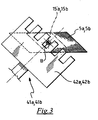
- barycentric grip condition and/or “barycentric position” is used to indicate a condition and/or position wherein the reinforcement element is gripped or held at a surface portion thereof extending symmetrically on opposite sides with respect to the barycentre of the reinforcement element.
- WO 2008/077418 discloses a process for manufacturing a tyre.
- the process comprises providing a first plurality of strip-like elements, each substantially having a first effective width; providing at least a second plurality of strip-like elements, each substantially having a second effective width different from the first effective width; arranging the strip-like elements of the first plurality and of the second plurality on a support by approaching side edges portions thereof to one another, so as to form at least one reinforcing component of the tyre on said support.
- EP 0 956 940 describes a process for manufacturing a reinforcement layer in a tyre being formed on a forming support.
- Such reinforcement layer is obtained by sequentially depositing a plurality of reinforcement elements on the forming support, along a circumferential direction of an outer peripheral surface thereof.
- Such reinforcement elements are cut to size in a proper cutting group from a reinforcement band-like element. Subsequent to the cut, each reinforcement element is picked up by proper gripping members and deposited on the outer peripheral surface of the forming support.
- WO 2010/067139 describes a process for manufacturing tyres for vehicle wheels, wherein a reinforcement annular structure is associated at each one of the axially opposite end edges of a carcass ply deposited on a substantially cylindrical forming support, such annular reinforcement structure being obtained by deposition on the carcass ply of a plurality of reinforcement elements cut to size from a reinforced continuous band-like element fed in the proximity of the forming support.
- Each reinforcement element, once cut to size, is picked up by a gripping member for the subsequent deposition on the carcass ply.
- the gripping member transfers the reinforcement element to a positioning member which in turn deposits it on the respective end edge of the carcass ply.
- the present invention relates to a process according to claim 1.
- the process of the present invention provides for a gripping condition of the reinforcement elements in a barycentric position, it advantageously allows, in a very simple and effective manner (thus without any burden in terms of labour cost and manufacturing time) an accurate and repeatable deposition condition on the tyre component to be maintained as the cutting length of the above reinforcement elements changes.
- the present invention relates to an apparatus according to claim 11.
- the present invention relates to an apparatus for manufacturing tyres for vehicle wheels comprising an apparatus for building at least one reinforcement structure as described above.
- the present invention in at least one of the above aspects thereof, can comprise at least one of the following preferred features.
- the second operative position is far from the first operative position by a distance whose extension, along the feeding direction, is defined on the basis of the difference between said at least one second cutting length and said first cutting length.
- said extension is equal, in absolute value, to half the difference between said at least one second cutting length and said first cutting length.
- translating the cutting group comprises:
- the above provisions allow the desired barycentric grip of the reinforcement elements to always be achieved irrespective of the extent of the required cutting length variation.
- depositing said at least one first reinforcement element comprises:
- said positioning takes place always in the desired circumferentially symmetrical position with respect to a radial plane of the forming support.
- moving said at least one first reinforcement element comprises:
- positioning said at least one first reinforcement element comprises:
- depositing said at least one second reinforcement element comprises:
- moving said at least one second reinforcement element from the cutting group towards the forming support comprises:
- positioning said at least one second reinforcement element comprises:
- picking said at least one first reinforcement element and at least one second reinforcement element up from the cutting group through said gripping member comprises:
- each reinforcement element from the gripping member to the positioning member is carried out at the barycentric position of said reinforcement element.
- said at least one tyre component is at least one carcass ply.
- said respective deposition area is defined on an end edge of said at least one carcass ply.
- the cutting group is mounted on a support frame through the interposition of a sliding rail extending along said feeding direction.
- Such sliding rail advantageously allows the movement of the cutting group in the most appropriate operative position on the basis of the required cutting length.
- said at least one moving and depositing device comprises:
- said at least one moving and depositing device further comprises:
- the apparatus comprises two positioning members arranged on opposite sides with respect to a middle plane of said apparatus.
- the middle plane of the apparatus of the present invention corresponds to an axial symmetry plane of the tyre being formed, i.e. to the equatorial plane of the tyre.
- the forming support is substantially cylindrical.
- reference numeral 100 globally indicates an exemplary embodiment of an apparatus for manufacturing tyres for vehicle wheels according to the present invention.
- apparatus 100 may be used in a process for manufacturing different batches of tyres.
- apparatus 100 allows associating respective reinforcement structures to specific tyre components.
- apparatus 100 is used for building carcass structures.
- Such building in particular comprises forming a first annular reinforcement structure 1a, 1b at each end edge 2a, 2b of a first carcass ply 2 deposited on a forming support 150 for manufacturing a first batch of tyres, and forming an annular reinforcement structure 1a, 1b at each end edge 2a, 2b of a second carcass ply 2' deposited on the forming support 150, for manufacturing a second batch of tyres differing from the tyres of the first batch at least by the width of the reinforcement structure and/or the deposition angle of the reinforcement element on the end edge of the carcass ply.
- the forming support 150 is cylindrical.
- the above end edges 2a, 2b are defined at axial end zones of the carcass ply 2, 2' configured to define the bead region of the tyres.
- Each reinforcement structure 1a, 1b extends in a circumferential direction on the respective end edge 2a, 2b of the carcass ply 2 and is defined by a predetermined number of reinforcement elements 5a, 5b, having the same length L1 and width W, deposited one after the other on respective deposition areas defined on the opposite end edges 2a, 2b of the carcass ply 2.
- figure 1 shows a reinforcement structure 1a being formed through deposition of the reinforcement elements 5a at the end edge 2a of the carcass ply 2 and a reinforcement structure 1b being formed through deposition of the reinforcement elements 5b at the opposite end edge 2b of the carcass ply 2.
- Apparatus 100 comprises a support frame 101 whereto, in operation, the forming support 150 is moved close and on which the various members or devices needed for forming the reinforcement structures 1a, 1b are mounted.
- the forming support 150 is periodically controlled in rotation about the axis of rotation X-X thereof by an angle corresponding to a predetermined circumferential step.
- the reinforcement elements 5a, 5b are preferably obtained by operations of cutting to size at least one reinforced continuous band-like element 4 extending along a direction of longitudinal extension, indicated with letter G in figure 1 , and fed close to the forming support 150 through a proper feeding device 20.
- the reinforced continuous band-like element 4 has a defined and constant width W, preferably comprised between 1 and 100 mm, more preferably between 30 and 70 mm.
- the reinforced continuous band-like element 4 is fed along the direction G of longitudinal extension thereof by the feeding device 20 with a predetermined advancing step, such step defining a predetermined cutting length L1 of the reinforced continuous band-like element 4, which corresponds to a predetermined width of the reinforcement elements 5a, 5b when they are deposited on the forming support 150.
- Apparatus 100 comprises a cutting group 30 configured to carry out the sequential operations of cutting to size the reinforced continuous band-like element 4 for obtaining the reinforcing elements 5a, 5b in a sequence.
- the cutting group 30 acts on the continuous reinforced band-like element 4, with a predetermined cutting frequency, along a cutting direction defining, on the lying plane of the reinforced continuous band-like element 4, a predetermined cutting angle ⁇ with the direction G of longitudinal extension of the reinforced continuous band-like element 4.
- the cutting angle ⁇ is set to a value greater than zero, preferably comprised between about 15° and about 90°, more preferably between about 20° and about 50°, even more preferably between about 22° and about 45°.
- length L1 of the reinforcement elements 5a, 5b deposited on the forming support 150 corresponds to width W of the reinforced continuous band-like element 4. If the cutting angle ⁇ is smaller than 90°, length L1 of the reinforcement elements 5a, 5b is equal to width W of the reinforced continuous band-like element 4 divided by the sine of angle ⁇ .
- the cutting group 30 is pivoted to frame 101 about a respective axis of rotation and can rotate as a whole around such axis for allowing the cutting of the reinforced continuous band-like element 4 with different angles ⁇ .
- the cutting group 30 is mounted on a pair of sliding rails 31 associated with support frame 101 and extending parallel to the feeding direction G of the reinforced continuous band-like element 4. In this way, the cutting group 30 can translate along the feeding direction G of the reinforced continuous band-like element 4 for positioning at operative positions different from that shown in figure 1 , thus allowing the cut of reinforcement elements having lengths different from that of the reinforcement elements 5a, 5b.
- the different operative positions of the cutting group 30 are defined on the basis of the desired cutting length of the reinforcement elements.
- apparatus 100 comprises a proper control device 35 associated with the cutting group 30.
- a moving and depositing device of the reinforcement elements 5a, 5b is provided downstream of the cutting group 30, i.e. between the cutting group 30 and the forming support 150.
- the moving and depositing device in particular comprises a gripping member 40 of the reinforcement elements 5a, 5b.
- the gripping member 40 comprises a pair of arms 41a, 41b configured to alternately pick the reinforcement element 5a, 5b just made up to move it towards the respective end edge 2a, 2b of the carcass ply 2 deposited on the forming support 150.
- Arms 41a, 41b are fixedly connected to one another and angularly spaced by a predetermined angle, preferably equal to 90°.
- Each arm 41a, 41b comprises, at a free end thereof, a clamp 42a, 42b for gripping the reinforcement element 5a, 5b to be cut.
- Each clamp 42a, 42b is slidingly mounted on the respective arm 41a, 42b so as to carry out a linear sliding movement with respect to arms 41a, 41b along the respective longitudinal directions. Such movement allows the release of the reinforcement element 5a, 5b just cut from the cutting group 30 for the subsequent movement thereof towards the forming support 150.
- the gripping member 40 is pivoted to frame 101 around a respective axis of rotation Y 1 defined at a plane M of apparatus 100, such plane M corresponding to the equatorial plane of the tyre being formed on the forming support 150.
- the gripping member 40 can rotate about axis Y 1 in both directions of rotation with an alternating movement, so as to move in an alternating sequence the reinforcement elements 5a towards the end edge 2a of the carcass ply 2 and the reinforcement elements 5b towards the end edge 2b of the carcass ply 2.
- the moving and depositing device further comprises, between the gripping member 40 and the forming support 150, a pair of positioning members 50a, 50b, each configured for picking a respective reinforcement element 5a, 5b up from a respective arm 41a, 41b of the gripping member 40 at a respective transfer position after such arm has made a predetermined angular movement (preferably equal to 90°) starting from the cutting group 30.
- the positioning members 50a, 50b (which are absolutely identical to one another) are preferably arranged symmetrically on the opposite sides with respect to plane M of apparatus 100 and are moved synchronously with arms 41a, 41b.
- Each reinforcement element 5a, 5b can thus be transferred by a respective arm 41a, 41b of the gripping member 40 to a respective positioning member 50a, 50b, which then deposits the reinforcement element 5a, 5b on a respective end edge 2a, 2b of the carcass ply 2 deposited on the forming support 150.
- Each positioning member 50a, 50b comprises a respective articulated arm in turn comprising a first arm 51a, 51b having a free end pivoted on frame 101 at a pivoting axis Y 2 , and a second arm 52a, 52b having a free end pivoted at a pivoting axis Y 3 on a free end of the respective first arm 51a, 52a opposite the one where the respective first arm 51a, 52a is pivoted to frame 101.
- Each second arm 52a, 52b comprises, at a free end thereof opposite the one where the second arm 52a, 52b is pivoted to the first arm 51a, 51b, a respective support member 53a, 53b configured to pick the respective reinforcement element 5a, 5b up from the respective arm 41a, 41b of the gripping member 40 at the above transfer position for moving it to the respective end edge 2a, 2b of the carcass ply 2 deposited on the forming support 150.
- Each support member 53a, 53b is provided with a device for holding the reinforcement element 5a, 5b by suction or suction cup or electromagnet (according to whether the reinforcement cords inside the reinforcement elements are textile or metal), configured to prevent the reinforcement element 5a, 5b from falling down during the movement towards the forming support 150.
- Each support member 53a, 53b is movable parallel to the pivoting axes Y 2 and Y 3 for allowing the deposition of the reinforcement elements 5a, 5b on the end edges 2a, 2b of the carcass ply 2 deposited on the forming support 150.
- the support members 53a, 53b after having deposited the reinforcement elements 5a, 5b on the respective end edges 2a, 2b of the carcass ply 2, press such reinforcement elements 5a, 5b against the forming support 150 so as to deform them consistently with the geometry of the forming support 150, thus achieving the complete laying of the reinforcement elements 5a, 5b on the above end edges 2a, 2b.
- a pair of respective pressing members configured to press on the reinforcement elements 5a, 5b after they have been deposited by the support members 53a, 53b on the above end edges 2a, 2b are provided downstream of the positioning members 50a, 50b, i.e. between the positioning members 50a, 50b and the forming support 150.
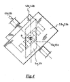
- the reinforcement elements 5a, 5b are each time deposited on the end edges 2a, 2b at respective deposition areas defined in circumferentially symmetrical positions with respect to a vertical radial plane of the forming support 150, that is so that barycentre B of the reinforcement element 5a, 5b deposited is on said radial plane, as shown in figure 5 .
- Apparatus 100 may further comprise a pair of idle rollers (not shown in the figures) movable perpendicularly to the rotation axis X-X of the forming support 150. Such rollers are coated with a deformable material and are arranged at opposite sides with respect to plane M of apparatus 100, each one in the proximity of a respective positioning member 50a, 50b.
- the above rollers are configured to be activated when the respective reinforcement structure 1a, 1b has been completed at each end edge 2a, 2b of the carcass ply 2 for improving the compaction and adhesion of said reinforcement structure 1a, 1b on the carcass ply 2.
- a carcass ply 2 is deposited on the forming support 150 and the forming support 150 is moved close to frame 101.
- Apparatus 100 is then set up on the basis of the features of the tyres to be made.
- the setup of apparatus 100 comprises, among the other things, the positioning of the cutting group 30 at the desired cutting angle ⁇ with respect to the feeding direction G of the reinforced continuous band-like element 4.
- the above setup further comprises the positioning of the cutting group 30 in an operative position defined along the feeding direction G of the reinforced continuous band-like element 4 on the basis of the desired cutting length L1.
- the reinforcement elements 5a, 5b are cut in a sequence from the reinforced continuous band-like element 4 and they are alternately deposited each on a respective end edge 2a, 2b of the carcass ply 2.
- the deposition of a reinforcement element 5a on an end edge 2a takes place immediately after a reinforcement element 5b has been deposited on the other end edge 2b and vice versa, so as to make a reinforcement structure 1a on the end edge 2a while another reinforcement structure 1b is made on the end edge 2b.
- the reinforced continuous band-like element 4 is moved along said feeding direction G by a predetermined advancing step.
- gripping member 40 is made to rotate so as to bring arm 41a at the cutting group 30. In this position, arm 41a is activated to pick a free end of the reinforced continuous band-like element 4 up.
- the reinforced continuous band-like element 4 is cut to obtain the reinforcement element 5a.
- Figure 1 shows an operative configuration of the apparatus and process of the present invention wherein the reinforcement element 5b just cut has been picked up by clamp 42b of arm 41b of the gripping member 40 and the latter has been moved by about 90° to bring clamp 42b to a transfer position of the reinforcement element 5b to the positioning member 50b which meanwhile has been moved towards the gripping member 40.
- arm 41a of the gripping member 40 has been brought at the cutting group 30 for picking up the reinforcement element 5a which is about to be cut from the reinforced continuous band-like element 4.
- the latter is made to rotate about the pivoting axis Y 2 to bring the above reinforcement element 5b at the end edge 2b of the carcass ply 2. During such rotation, the reinforcement element 5b is held at the barycentric position on the support member 53b of the positioning member 50b by the holding device described above.
- the forming support 150 is made to rotate about axis X-X by a predetermined angle corresponding to a movement in the circumferential direction by a length equal to (if the circumferentially consecutive reinforcement elements 5a, 5b must be deposited in contact with each other and without overlapping) or greater than (if the reinforcement elements 5a, 5b must be deposited leaving a free space between two circumferentially consecutive reinforcement elements) the advancing step of the reinforced continuous band-like element 4.
- the support member 53b is moved towards the forming support 150 (and thus in a direction perpendicular to the rotation axis X-X of the forming support 150) up to positioning the reinforcement element 5b on a respective deposition area defined on the end edge 2b of the carcass ply 2.
- the support member 53b exerts a predetermined thrust action against the forming support 150, so as to obtain the complete laying of the reinforcement element 5b on the end edge 2b of the carcass ply 2.
- said thrust action may be carried out by a pressing member separate from the support member 53b.
- the process described above is repeated cyclically through the positioning members 50a and 50b, each time depositing a new reinforcement element 5a, 5b on the respective end edge 2a, 2b of the carcass ply 2, up to completing the reinforcement structures 1a, 1b on both end edges 2a, 2b of the carcass ply 2.
- each one of such idle rollers is brought in contact with the respective reinforcement structure 1a, 1b just formed.
- the rotation of the forming support 150 is then controlled for at least one full revolution.
- the action of the rollers during such rotation produces the compaction of the reinforcement structures 1a, 1b on the respective end edges 2a, 2b of the carcass ply 2.
- a process totally similar to that described above may be carried out by the same apparatus 100 for manufacturing a second batch of tyres differing from the tyres of the first batch in that the reinforcement structures 1a, 1b of the tyres of the second batch comprise reinforcement elements 15a, 15b having a cutting length L2 different from the cutting length of the reinforcement elements 5a, 5b of the tyres of the first batch.
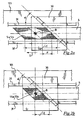
- length L2 is lower than length L1, as shown in figure 2b .
- the cutting group 30 is first translated along the feeding direction G of the reinforced continuous band-like element 4 towards barycentre B of the reinforcement elements 5a, 5b previously cut (i.e. in the direction indicated by arrow T in figure 2a ).
- the cutting group 30 is moved from a first operative position taken for cutting the reinforcement elements 5a, 5b having length L1 to a new operative position which is far from the first operative position by a distance P whose longitudinal extension along the feeding direction G is a function of the difference between length L1 and length L2 ( figures 2a and 2b ).
- said extension is equal to half the difference between length L1 and length L2.
- length L2 is greater than length L1
- the movement of the cutting group 30 takes place in a direction opposite to that indicated with letter T in figure 2 (i.e. away from barycentre B of the reinforcement elements 5a, 5b previously cut) and the extent of distance P is equal to half the difference between length L2 and length L1.
Landscapes
- Engineering & Computer Science (AREA)
- Mechanical Engineering (AREA)
- Tyre Moulding (AREA)
Claims (15)
- Verfahren zur Herstellung von Reifen für Fahrzeugräder, umfassend das Zuordnen zumindest einer Verstärkungsstruktur (1a, 1b) an zumindest eine Reifenkomponente (2, 2'), die auf einem Formungsträger (150) gebildet sind, wobei das Zuordnen zumindest einer Verstärkungsstruktur (1a, 1b) umfasst:- Zuführen eines verstärkten durchgehenden streifenförmigen Elements (4) an eine Schneidgruppe (30), indem es entlang einer Zuführrichtung (G) mit einem ersten Vorschubschritt bewegt wird, wobei die Schneidgruppe (30) entlang der Zuführrichtung (G) in einer ersten Betriebsstellung angeordnet ist;- Zuschneiden des verstärkten durchgehenden streifenförmigen Elements (4), um zumindest ein erstes Verstärkungselement (5a, 5b) mit einer ersten Schnittlänge (L1) zu bilden;- Ablegen des zumindest einen ersten Verstärkungselements (5a, 5b) auf einem jeweiligen Ablagebereich, der an einer jeweiligen Komponente eines ersten Reifens (2) definiert ist;- Verschieben der Schneidgruppe (30) entlang der Zuführrichtung (G) aus der ersten Betriebsstellung in eine zweite Betriebsstellung;- Bewegen des verstärkten durchgehenden streifenförmigen Elements (4) entlang der Zuführrichtung (G) mit einem zweiten Vorschubschritt, der sich von dem ersten Vorschubschritt unterscheidet;- Zuschneiden des verstärkten durchgehenden streifenförmigen Elements (4), um zumindest ein zweites Verstärkungselement (15a, 15b) zu bilden, das zumindest eine zweite Schnittlänge (L2) aufweist, die sich von der ersten Schnittlänge (L1) unterscheidet;- Ablegen des zumindest einen zweiten Verstärkungselements (15a, 15b) auf einem jeweiligen Ablagebereich, der an einer jeweiligen Komponente eines zweiten Reifens (2') definiert ist;
wobei die zweite Betriebsstellung auf der Grundlage der zumindest einen zweiten Schnittlänge (L2) definiert ist. - Verfahren nach Anspruch 1, wobei die zweite Betriebsstellung von der ersten Betriebsstellung um einen Abstand entfernt ist, dessen Erstreckung entlang der Zuführrichtung (G) auf der Grundlage der Differenz zwischen der zumindest einen zweiten Schnittlänge (L2) und der ersten Schnittlänge (L1) definiert ist.
- Verfahren nach Anspruch 2, wobei die Erstreckung in absoluten Werten gleich der Hälfte der Differenz zwischen der zumindest einen zweiten Schnittlänge (L2) und der ersten Schnittlänge (L1) ist.
- Verfahren nach einem der vorhergehenden Ansprüche, wobei das Verschieben der Schneidgruppe (30) umfasst:- Bewegen der Schneidgruppe (30) entlang der Zuführrichtung (G) jeweils von dem Schwerpunkt des zumindest einen ersten Verstärkungselements (5a, 5b) weg oder zu diesem hin, in Abhängigkeit davon, ob die zumindest eine zweite Schnittlänge (L2) jeweils größer oder kleiner ist als die erste Schnittlänge (L1).
- Verfahren nach einem der vorhergehenden Ansprüche, wobei das Ablegen des zumindest einen ersten Verstärkungselements (5a, 5b) umfasst:- Bewegen des zumindest einen ersten Verstärkungselements (5a, 5b) von der Schneidgruppe (30) zu dem Formungsträger (150) hin;- Ablegen des zumindest einen ersten Verstärkungselements (5a, 5b) auf dem jeweiligen Ablagebereich.
- Verfahren nach einem der vorhergehenden Ansprüche, wobei das Bewegen des zumindest einen ersten Verstärkungselements (5a, 5b) umfasst:- Aufnehmen des zumindest einen ersten Verstärkungselements (5a, 5b) von der Schneidgruppe (30) durch ein Greifelement (40) und Bewegen in eine Übergabestellung des zumindest einen ersten Verstärkungselements (5a, 5b) an ein Positionierelement (50a, 50b).
- Verfahren nach Anspruch 5 oder 6, wobei das Ablegen des zumindest einen zweiten Verstärkungselements (15a, 15b) umfasst:- Bewegen des zumindest einen zweiten Verstärkungselements (15a, 15b) von der Schneidgruppe (30) zu dem Formungsträger (150) hin;- Ablegen des zumindest einen zweiten Verstärkungselements (15a, 15b) auf dem jeweiligen Ablagebereich.
- Verfahren nach Anspruch 7, sofern abhängig von Anspruch 6, wobei das Bewegen des zumindest einen zweiten Verstärkungselements (15a, 15b) von der Schneidgruppe (30) zu dem Formungsträger (150) hin umfasst:- Aufnehmen des zumindest einen zweiten Verstärkungselements (15a, 15b) von der Schneidgruppe (30) durch das Greifelement (40) und Bewegen in die Übergabestellung an das Positionierelement (50a, 50b).
- Verfahren nach den Ansprüchen 6 und 8, wobei das Aufnehmen des zumindest einen ersten Verstärkungselements (5a, 5b) und des zumindest einen zweiten Verstärkungselements (15a, 15b) von der Schneidgruppe (30) durch das Greifelement (40) umfasst:- Positionieren des Greifelements (40) an einer Schwerpunktstellung des ersten Verstärkungselements (5a, 5b) und des zweiten Verstärkungselements (15a, 15b);- Halten des jeweiligen Verstärkungselements (5a, 5b, 15a, 15b) in der Schwerpunktstellung.
- Verfahren nach Anspruch 9, wobei die Übergabe jedes Verstärkungselements (5a, 5b, 15a, 15b) von dem Greifelement (40) an das Positionierelement (50a, 50b) an der Schwerpunktstellung des Verstärkungselements (5a, 5b, 15a, 15b) ausgeführt wird.
- Vorrichtung (100) zur Herstellung zumindest einer Verstärkungsstruktur (1a, 1b) an einer Reifenkomponente (2, 2'), die an einem Formungsträger (150) gebildet wird, wobei die Vorrichtung umfasst:- eine Einrichtung (20) zum Zuführen eines verstärkten durchgehenden streifenförmigen Elements (4) entlang einer Zuführrichtung (G);- eine Schneidgruppe (30) für das verstärkte durchgehende streifenförmige Element (4), um zumindest ein erstes Verstärkungselement (5a, 5b) und zumindest ein zweites Verstärkungselement (15a, 15b) zu bilden, die jeweils eine erste Schnittlänge (L1) und zumindest eine zweite Schnittlänge (L2) aufweisen, die sich von der ersten Schnittlänge (L1) unterscheidet;- zumindest eine Bewegungs- und Ablageeinrichtung (40, 50a, 50b) zum Bewegen des zumindest einen ersten Verstärkungselements (5a, 5b) und des zumindest einen zweiten Verstärkungselements (15a, 15b) nahe an den Formungsträger (150) und zum Ablegen des zumindest einen ersten Verstärkungselement (5a, 5b) und des zumindest einen zweiten Verstärkungselements (15a, 15b) an jeweiligen Ablagebereichen, die an jeweiligen Reifenkomponenten (2, 2') definiert sind;- eine Einrichtung (35) zur Steuerung der Verschiebung der Schneidgruppe (30) entlang der Zuführrichtung (G) zwischen einer ersten Betriebsstellung, die auf der Grundlage der ersten Schnittlänge (L1) definiert ist, und einer zweiten Betriebsstellung, die auf der Grundlage der zumindest einen zweiten Schnittlänge (L2) definiert ist.
- Vorrichtung (100) nach Anspruch 11, wobei die Schneidgruppe (30) an einem Tragrahmen (101) montiert ist, unter Zwischenschaltung einer Gleitschiene (31), die sich entlang der Zuführrichtung (G) erstreckt.
- Vorrichtung (100) nach Anspruch 11 oder 12, wobei die zumindest eine Bewegungs- und Ablegeeinrichtung (40, 50a, 50b) umfasst:- zumindest ein Greifelement (40) für das zumindest eine erste Verstärkungselement (5a, 5b) und das zumindest eine zweite Verstärkungselement (15a, 15b), wobei das zumindest eine Greifelement (40) zwischen der Schneidgruppe (30) und einer Übergabestellung beweglich ist.
- Vorrichtung (100) nach Anspruch 13, wobei die zumindest eine Bewegungs- und Ablegeeinrichtung (50, 50a, 50b) des Weiteren umfasst:- zumindest ein Positionierelement (50a, 50b), das zwischen der Übergabestellung und einer Ablegestellung, die an dem Formungsträger (150) definiert ist, beweglich ist.
- Vorrichtung (100) nach Anspruch 13 oder 14, umfassend zwei Positionierelemente (50a, 50b), die an entgegengesetzten Seiten in Bezug auf eine Mittelebene (M) der Vorrichtung (100) angeordnet sind.
Applications Claiming Priority (3)
| Application Number | Priority Date | Filing Date | Title |
|---|---|---|---|
| IT002349A ITMI20112349A1 (it) | 2011-12-22 | 2011-12-22 | Processo ed apparato per la produzione di pneumatici per ruote di veicoli |
| US201161580937P | 2011-12-28 | 2011-12-28 | |
| PCT/IB2012/057518 WO2013093827A1 (en) | 2011-12-22 | 2012-12-20 | Process and apparatus for manufacturing tyres for vehicle wheels |
Publications (2)
| Publication Number | Publication Date |
|---|---|
| EP2794251A1 EP2794251A1 (de) | 2014-10-29 |
| EP2794251B1 true EP2794251B1 (de) | 2016-04-06 |
Family
ID=45540969
Family Applications (1)
| Application Number | Title | Priority Date | Filing Date |
|---|---|---|---|
| EP12823025.7A Active EP2794251B1 (de) | 2011-12-22 | 2012-12-20 | Verfahren und vorrichtung zur herstellung von reifen für fahrzeugräder |
Country Status (6)
| Country | Link |
|---|---|
| US (2) | US9205614B2 (de) |
| EP (1) | EP2794251B1 (de) |
| CN (1) | CN104114353B (de) |
| BR (1) | BR112014015591B1 (de) |
| IT (1) | ITMI20112349A1 (de) |
| WO (1) | WO2013093827A1 (de) |
Families Citing this family (2)
| Publication number | Priority date | Publication date | Assignee | Title |
|---|---|---|---|---|
| WO2016126684A2 (en) * | 2015-02-06 | 2016-08-11 | The Steelastic Company, Llc | Belt forming system |
| JP7572628B2 (ja) * | 2021-03-04 | 2024-10-24 | 横浜ゴム株式会社 | タイヤの製造方法および成形装置 |
Family Cites Families (12)
| Publication number | Priority date | Publication date | Assignee | Title |
|---|---|---|---|---|
| US3874974A (en) * | 1970-09-28 | 1975-04-01 | Jr Kenneth I Simmons | Application of tread strip to tire casing |
| US3904471A (en) * | 1974-10-15 | 1975-09-09 | Goodyear Tire & Rubber | Tire building apparatus |
| JPH064293B2 (ja) * | 1989-12-21 | 1994-01-19 | 住友ゴム工業株式会社 | 帯状シート体成形方法及び成形装置 |
| WO1999017920A1 (fr) | 1997-10-03 | 1999-04-15 | Bridgestone Corporation | Procede et appareil pour former une couche de renfort d'un pneu |
| US6841017B2 (en) * | 2000-09-14 | 2005-01-11 | Bridgestone Corporation | Re-treading method and apparatus |
| WO2006064525A1 (en) * | 2004-12-16 | 2006-06-22 | Pirelli Tyre S.P.A. | Method and plant for manufacturing tyres for vehicle wheels |
| DE602006016346D1 (de) * | 2006-05-30 | 2010-09-30 | Pirelli | Verfahren und vorrichtung zur herstellung von reifen für fahrzeugräder |
| US20100288423A1 (en) * | 2006-06-29 | 2010-11-18 | Pirelli Tyre S.P.A. | Process for manufacturing tyres for vehicle wheels |
| BRPI0622215A2 (pt) * | 2006-12-22 | 2012-01-03 | Pirelli | processo para fabricar um pneu, e, pneu |
| BRPI0721788B1 (pt) * | 2007-06-29 | 2018-07-03 | Pirelli Tyre S.P.A. | Processo e aparelho para a fabricação de pneus para rodas de veículos |
| JP5134733B2 (ja) * | 2008-12-11 | 2013-01-30 | ピレリ・タイヤ・ソチエタ・ペル・アツィオーニ | 車両車輪用タイヤの製造方法及び装置 |
| GB201005308D0 (en) | 2010-03-30 | 2010-05-12 | Airbus Operations Ltd | Composite structural member |
-
2011
- 2011-12-22 IT IT002349A patent/ITMI20112349A1/it unknown
-
2012
- 2012-12-20 EP EP12823025.7A patent/EP2794251B1/de active Active
- 2012-12-20 CN CN201280069540.4A patent/CN104114353B/zh active Active
- 2012-12-20 US US14/365,366 patent/US9205614B2/en active Active
- 2012-12-20 WO PCT/IB2012/057518 patent/WO2013093827A1/en not_active Ceased
- 2012-12-20 BR BR112014015591-7A patent/BR112014015591B1/pt active IP Right Grant
-
2015
- 2015-10-29 US US14/926,955 patent/US10118356B2/en active Active
Also Published As
| Publication number | Publication date |
|---|---|
| US20160144584A1 (en) | 2016-05-26 |
| US20140374008A1 (en) | 2014-12-25 |
| BR112014015591B1 (pt) | 2020-12-15 |
| EP2794251A1 (de) | 2014-10-29 |
| CN104114353B (zh) | 2016-08-17 |
| US9205614B2 (en) | 2015-12-08 |
| BR112014015591A2 (pt) | 2017-06-13 |
| WO2013093827A1 (en) | 2013-06-27 |
| US10118356B2 (en) | 2018-11-06 |
| ITMI20112349A1 (it) | 2013-06-23 |
| CN104114353A (zh) | 2014-10-22 |
Similar Documents
| Publication | Publication Date | Title |
|---|---|---|
| EP2640569B1 (de) | Verfahren und vorrichtung zur herstellung von fahrzeugreifen | |
| EP2219856A1 (de) | Verfahren und vorrichtung zur herstellung von reifen für fahrzeugräder | |
| US20190344518A1 (en) | Method, process and plant for controlling the manufacture of tyres for vehicle wheels | |
| US20180009186A1 (en) | Process for manufacturing tyres for vehicle wheels | |
| EP3233458B1 (de) | Verfahren und vorrichtung zur herstellung von reifen für fahrzeugräder | |
| EP2488356B1 (de) | Verfahren und vorrichtung zur herstellung von reifen für fahrzeugräder | |
| EP2794251B1 (de) | Verfahren und vorrichtung zur herstellung von reifen für fahrzeugräder | |
| RU2499670C2 (ru) | Способ и установка для производства шин для колес транспортного средства | |
| US9168709B2 (en) | Process and apparatus for manufacturing tyres for vehicle wheels | |
| US20080314504A1 (en) | Method and Plant for Manufacturing Tyres for Vehicle Wheels | |
| EP2200815B1 (de) | Verfahren zur Herstellung einer Verstärkungsstruktur für Fahrzeugreifen | |
| EP2170593B1 (de) | Verfahren und vorrichtung zur herstellung von reifen für fahrzeugräder | |
| EP2707201B1 (de) | Verfahren und anlage zur herstellung von reifen fuer fahrzeugräder | |
| EP3487693B1 (de) | Verfahren und vorrichtung zur herstellung von reifen für fahrzeugräder | |
| EP2046567B1 (de) | Verfahren und vorrichtung zur herstellung einer verstärkungsstruktur für fahrzeugreifen |
Legal Events
| Date | Code | Title | Description |
|---|---|---|---|
| PUAI | Public reference made under article 153(3) epc to a published international application that has entered the european phase |
Free format text: ORIGINAL CODE: 0009012 |
|
| 17P | Request for examination filed |
Effective date: 20140710 |
|
| AK | Designated contracting states |
Kind code of ref document: A1 Designated state(s): AL AT BE BG CH CY CZ DE DK EE ES FI FR GB GR HR HU IE IS IT LI LT LU LV MC MK MT NL NO PL PT RO RS SE SI SK SM TR |
|
| DAX | Request for extension of the european patent (deleted) | ||
| GRAP | Despatch of communication of intention to grant a patent |
Free format text: ORIGINAL CODE: EPIDOSNIGR1 |
|
| INTG | Intention to grant announced |
Effective date: 20150618 |
|
| INTG | Intention to grant announced |
Effective date: 20151201 |
|
| GRAS | Grant fee paid |
Free format text: ORIGINAL CODE: EPIDOSNIGR3 |
|
| GRAA | (expected) grant |
Free format text: ORIGINAL CODE: 0009210 |
|
| AK | Designated contracting states |
Kind code of ref document: B1 Designated state(s): AL AT BE BG CH CY CZ DE DK EE ES FI FR GB GR HR HU IE IS IT LI LT LU LV MC MK MT NL NO PL PT RO RS SE SI SK SM TR |
|
| REG | Reference to a national code |
Ref country code: GB Ref legal event code: FG4D |
|
| REG | Reference to a national code |
Ref country code: AT Ref legal event code: REF Ref document number: 787274 Country of ref document: AT Kind code of ref document: T Effective date: 20160415 Ref country code: CH Ref legal event code: EP |
|
| REG | Reference to a national code |
Ref country code: IE Ref legal event code: FG4D |
|
| REG | Reference to a national code |
Ref country code: DE Ref legal event code: R096 Ref document number: 602012016870 Country of ref document: DE |
|
| REG | Reference to a national code |
Ref country code: RO Ref legal event code: EPE |
|
| REG | Reference to a national code |
Ref country code: LT Ref legal event code: MG4D Ref country code: NL Ref legal event code: MP Effective date: 20160406 |
|
| REG | Reference to a national code |
Ref country code: AT Ref legal event code: MK05 Ref document number: 787274 Country of ref document: AT Kind code of ref document: T Effective date: 20160406 |
|
| PG25 | Lapsed in a contracting state [announced via postgrant information from national office to epo] |
Ref country code: NL Free format text: LAPSE BECAUSE OF FAILURE TO SUBMIT A TRANSLATION OF THE DESCRIPTION OR TO PAY THE FEE WITHIN THE PRESCRIBED TIME-LIMIT Effective date: 20160406 |
|
| PG25 | Lapsed in a contracting state [announced via postgrant information from national office to epo] |
Ref country code: LT Free format text: LAPSE BECAUSE OF FAILURE TO SUBMIT A TRANSLATION OF THE DESCRIPTION OR TO PAY THE FEE WITHIN THE PRESCRIBED TIME-LIMIT Effective date: 20160406 Ref country code: PL Free format text: LAPSE BECAUSE OF FAILURE TO SUBMIT A TRANSLATION OF THE DESCRIPTION OR TO PAY THE FEE WITHIN THE PRESCRIBED TIME-LIMIT Effective date: 20160406 Ref country code: NO Free format text: LAPSE BECAUSE OF FAILURE TO SUBMIT A TRANSLATION OF THE DESCRIPTION OR TO PAY THE FEE WITHIN THE PRESCRIBED TIME-LIMIT Effective date: 20160706 Ref country code: FI Free format text: LAPSE BECAUSE OF FAILURE TO SUBMIT A TRANSLATION OF THE DESCRIPTION OR TO PAY THE FEE WITHIN THE PRESCRIBED TIME-LIMIT Effective date: 20160406 Ref country code: IS Free format text: LAPSE BECAUSE OF FAILURE TO SUBMIT A TRANSLATION OF THE DESCRIPTION OR TO PAY THE FEE WITHIN THE PRESCRIBED TIME-LIMIT Effective date: 20160806 |
|
| PG25 | Lapsed in a contracting state [announced via postgrant information from national office to epo] |
Ref country code: RS Free format text: LAPSE BECAUSE OF FAILURE TO SUBMIT A TRANSLATION OF THE DESCRIPTION OR TO PAY THE FEE WITHIN THE PRESCRIBED TIME-LIMIT Effective date: 20160406 Ref country code: ES Free format text: LAPSE BECAUSE OF FAILURE TO SUBMIT A TRANSLATION OF THE DESCRIPTION OR TO PAY THE FEE WITHIN THE PRESCRIBED TIME-LIMIT Effective date: 20160406 Ref country code: LV Free format text: LAPSE BECAUSE OF FAILURE TO SUBMIT A TRANSLATION OF THE DESCRIPTION OR TO PAY THE FEE WITHIN THE PRESCRIBED TIME-LIMIT Effective date: 20160406 Ref country code: GR Free format text: LAPSE BECAUSE OF FAILURE TO SUBMIT A TRANSLATION OF THE DESCRIPTION OR TO PAY THE FEE WITHIN THE PRESCRIBED TIME-LIMIT Effective date: 20160707 Ref country code: AT Free format text: LAPSE BECAUSE OF FAILURE TO SUBMIT A TRANSLATION OF THE DESCRIPTION OR TO PAY THE FEE WITHIN THE PRESCRIBED TIME-LIMIT Effective date: 20160406 Ref country code: HR Free format text: LAPSE BECAUSE OF FAILURE TO SUBMIT A TRANSLATION OF THE DESCRIPTION OR TO PAY THE FEE WITHIN THE PRESCRIBED TIME-LIMIT Effective date: 20160406 Ref country code: SE Free format text: LAPSE BECAUSE OF FAILURE TO SUBMIT A TRANSLATION OF THE DESCRIPTION OR TO PAY THE FEE WITHIN THE PRESCRIBED TIME-LIMIT Effective date: 20160406 Ref country code: PT Free format text: LAPSE BECAUSE OF FAILURE TO SUBMIT A TRANSLATION OF THE DESCRIPTION OR TO PAY THE FEE WITHIN THE PRESCRIBED TIME-LIMIT Effective date: 20160808 |
|
| REG | Reference to a national code |
Ref country code: FR Ref legal event code: PLFP Year of fee payment: 5 |
|
| PG25 | Lapsed in a contracting state [announced via postgrant information from national office to epo] |
Ref country code: BE Free format text: LAPSE BECAUSE OF FAILURE TO SUBMIT A TRANSLATION OF THE DESCRIPTION OR TO PAY THE FEE WITHIN THE PRESCRIBED TIME-LIMIT Effective date: 20160406 Ref country code: IT Free format text: LAPSE BECAUSE OF FAILURE TO SUBMIT A TRANSLATION OF THE DESCRIPTION OR TO PAY THE FEE WITHIN THE PRESCRIBED TIME-LIMIT Effective date: 20160406 |
|
| REG | Reference to a national code |
Ref country code: DE Ref legal event code: R097 Ref document number: 602012016870 Country of ref document: DE |
|
| PG25 | Lapsed in a contracting state [announced via postgrant information from national office to epo] |
Ref country code: CZ Free format text: LAPSE BECAUSE OF FAILURE TO SUBMIT A TRANSLATION OF THE DESCRIPTION OR TO PAY THE FEE WITHIN THE PRESCRIBED TIME-LIMIT Effective date: 20160406 Ref country code: DK Free format text: LAPSE BECAUSE OF FAILURE TO SUBMIT A TRANSLATION OF THE DESCRIPTION OR TO PAY THE FEE WITHIN THE PRESCRIBED TIME-LIMIT Effective date: 20160406 Ref country code: SK Free format text: LAPSE BECAUSE OF FAILURE TO SUBMIT A TRANSLATION OF THE DESCRIPTION OR TO PAY THE FEE WITHIN THE PRESCRIBED TIME-LIMIT Effective date: 20160406 Ref country code: EE Free format text: LAPSE BECAUSE OF FAILURE TO SUBMIT A TRANSLATION OF THE DESCRIPTION OR TO PAY THE FEE WITHIN THE PRESCRIBED TIME-LIMIT Effective date: 20160406 |
|
| PLBE | No opposition filed within time limit |
Free format text: ORIGINAL CODE: 0009261 |
|
| STAA | Information on the status of an ep patent application or granted ep patent |
Free format text: STATUS: NO OPPOSITION FILED WITHIN TIME LIMIT |
|
| PG25 | Lapsed in a contracting state [announced via postgrant information from national office to epo] |
Ref country code: SM Free format text: LAPSE BECAUSE OF FAILURE TO SUBMIT A TRANSLATION OF THE DESCRIPTION OR TO PAY THE FEE WITHIN THE PRESCRIBED TIME-LIMIT Effective date: 20160406 |
|
| 26N | No opposition filed |
Effective date: 20170110 |
|
| PG25 | Lapsed in a contracting state [announced via postgrant information from national office to epo] |
Ref country code: SI Free format text: LAPSE BECAUSE OF FAILURE TO SUBMIT A TRANSLATION OF THE DESCRIPTION OR TO PAY THE FEE WITHIN THE PRESCRIBED TIME-LIMIT Effective date: 20160406 |
|
| REG | Reference to a national code |
Ref country code: CH Ref legal event code: PL |
|
| PG25 | Lapsed in a contracting state [announced via postgrant information from national office to epo] |
Ref country code: MC Free format text: LAPSE BECAUSE OF FAILURE TO SUBMIT A TRANSLATION OF THE DESCRIPTION OR TO PAY THE FEE WITHIN THE PRESCRIBED TIME-LIMIT Effective date: 20160406 |
|
| REG | Reference to a national code |
Ref country code: IE Ref legal event code: MM4A |
|
| PG25 | Lapsed in a contracting state [announced via postgrant information from national office to epo] |
Ref country code: CH Free format text: LAPSE BECAUSE OF NON-PAYMENT OF DUE FEES Effective date: 20161231 Ref country code: LI Free format text: LAPSE BECAUSE OF NON-PAYMENT OF DUE FEES Effective date: 20161231 Ref country code: LU Free format text: LAPSE BECAUSE OF NON-PAYMENT OF DUE FEES Effective date: 20161220 |
|
| PG25 | Lapsed in a contracting state [announced via postgrant information from national office to epo] |
Ref country code: IE Free format text: LAPSE BECAUSE OF NON-PAYMENT OF DUE FEES Effective date: 20161220 |
|
| REG | Reference to a national code |
Ref country code: FR Ref legal event code: PLFP Year of fee payment: 6 |
|
| PG25 | Lapsed in a contracting state [announced via postgrant information from national office to epo] |
Ref country code: HU Free format text: LAPSE BECAUSE OF FAILURE TO SUBMIT A TRANSLATION OF THE DESCRIPTION OR TO PAY THE FEE WITHIN THE PRESCRIBED TIME-LIMIT; INVALID AB INITIO Effective date: 20121220 |
|
| PG25 | Lapsed in a contracting state [announced via postgrant information from national office to epo] |
Ref country code: MK Free format text: LAPSE BECAUSE OF FAILURE TO SUBMIT A TRANSLATION OF THE DESCRIPTION OR TO PAY THE FEE WITHIN THE PRESCRIBED TIME-LIMIT Effective date: 20160406 Ref country code: CY Free format text: LAPSE BECAUSE OF FAILURE TO SUBMIT A TRANSLATION OF THE DESCRIPTION OR TO PAY THE FEE WITHIN THE PRESCRIBED TIME-LIMIT Effective date: 20160406 |
|
| PG25 | Lapsed in a contracting state [announced via postgrant information from national office to epo] |
Ref country code: BG Free format text: LAPSE BECAUSE OF FAILURE TO SUBMIT A TRANSLATION OF THE DESCRIPTION OR TO PAY THE FEE WITHIN THE PRESCRIBED TIME-LIMIT Effective date: 20160406 |
|
| PG25 | Lapsed in a contracting state [announced via postgrant information from national office to epo] |
Ref country code: MT Free format text: LAPSE BECAUSE OF NON-PAYMENT OF DUE FEES Effective date: 20161220 |
|
| PG25 | Lapsed in a contracting state [announced via postgrant information from national office to epo] |
Ref country code: AL Free format text: LAPSE BECAUSE OF FAILURE TO SUBMIT A TRANSLATION OF THE DESCRIPTION OR TO PAY THE FEE WITHIN THE PRESCRIBED TIME-LIMIT Effective date: 20160406 |
|
| PGFP | Annual fee paid to national office [announced via postgrant information from national office to epo] |
Ref country code: GB Payment date: 20251229 Year of fee payment: 14 |
|
| PGFP | Annual fee paid to national office [announced via postgrant information from national office to epo] |
Ref country code: FR Payment date: 20251226 Year of fee payment: 14 |
|
| PGFP | Annual fee paid to national office [announced via postgrant information from national office to epo] |
Ref country code: TR Payment date: 20251216 Year of fee payment: 14 |
|
| PGFP | Annual fee paid to national office [announced via postgrant information from national office to epo] |
Ref country code: RO Payment date: 20251205 Year of fee payment: 14 |
|
| PGFP | Annual fee paid to national office [announced via postgrant information from national office to epo] |
Ref country code: DE Payment date: 20251229 Year of fee payment: 14 |