EP2796573B1 - Tige de forage et son procédé de production - Google Patents
Tige de forage et son procédé de production Download PDFInfo
- Publication number
- EP2796573B1 EP2796573B1 EP14175519.9A EP14175519A EP2796573B1 EP 2796573 B1 EP2796573 B1 EP 2796573B1 EP 14175519 A EP14175519 A EP 14175519A EP 2796573 B1 EP2796573 B1 EP 2796573B1
- Authority
- EP
- European Patent Office
- Prior art keywords
- rod
- drill rod
- threaded part
- free end
- hardened
- Prior art date
- Legal status (The legal status is an assumption and is not a legal conclusion. Google has not performed a legal analysis and makes no representation as to the accuracy of the status listed.)
- Expired - Lifetime
Links
- 238000004519 manufacturing process Methods 0.000 title claims description 10
- 238000000034 method Methods 0.000 title claims description 6
- 238000003466 welding Methods 0.000 claims description 12
- 238000010438 heat treatment Methods 0.000 claims description 10
- 229910000831 Steel Inorganic materials 0.000 claims description 7
- 239000010959 steel Substances 0.000 claims description 7
- 229910000734 martensite Inorganic materials 0.000 claims description 6
- 238000005553 drilling Methods 0.000 claims description 3
- 239000011435 rock Substances 0.000 claims description 3
- 238000002844 melting Methods 0.000 description 9
- 230000008018 melting Effects 0.000 description 9
- 229910001563 bainite Inorganic materials 0.000 description 3
- 238000009826 distribution Methods 0.000 description 2
- 230000035939 shock Effects 0.000 description 2
- 238000001816 cooling Methods 0.000 description 1
- 238000011010 flushing procedure Methods 0.000 description 1
- 238000012432 intermediate storage Methods 0.000 description 1
- 239000000203 mixture Substances 0.000 description 1
- 235000019362 perlite Nutrition 0.000 description 1
- 239000010451 perlite Substances 0.000 description 1
- 239000007858 starting material Substances 0.000 description 1
- 238000003860 storage Methods 0.000 description 1
- XLYOFNOQVPJJNP-UHFFFAOYSA-N water Substances O XLYOFNOQVPJJNP-UHFFFAOYSA-N 0.000 description 1
Images


Classifications
-
- E—FIXED CONSTRUCTIONS
- E21—EARTH OR ROCK DRILLING; MINING
- E21B—EARTH OR ROCK DRILLING; OBTAINING OIL, GAS, WATER, SOLUBLE OR MELTABLE MATERIALS OR A SLURRY OF MINERALS FROM WELLS
- E21B17/00—Drilling rods or pipes; Flexible drill strings; Kellies; Drill collars; Sucker rods; Cables; Casings; Tubings
-
- C—CHEMISTRY; METALLURGY
- C21—METALLURGY OF IRON
- C21D—MODIFYING THE PHYSICAL STRUCTURE OF FERROUS METALS; GENERAL DEVICES FOR HEAT TREATMENT OF FERROUS OR NON-FERROUS METALS OR ALLOYS; MAKING METAL MALLEABLE, e.g. BY DECARBURISATION OR TEMPERING
- C21D9/00—Heat treatment, e.g. annealing, hardening, quenching or tempering, adapted for particular articles; Furnaces therefor
- C21D9/50—Heat treatment, e.g. annealing, hardening, quenching or tempering, adapted for particular articles; Furnaces therefor for welded joints
-
- E—FIXED CONSTRUCTIONS
- E21—EARTH OR ROCK DRILLING; MINING
- E21B—EARTH OR ROCK DRILLING; OBTAINING OIL, GAS, WATER, SOLUBLE OR MELTABLE MATERIALS OR A SLURRY OF MINERALS FROM WELLS
- E21B17/00—Drilling rods or pipes; Flexible drill strings; Kellies; Drill collars; Sucker rods; Cables; Casings; Tubings
- E21B17/02—Couplings; joints
- E21B17/04—Couplings; joints between rod or the like and bit or between rod and rod or the like
- E21B17/042—Threaded
- E21B17/0426—Threaded with a threaded cylindrical portion, e.g. for percussion rods
-
- C—CHEMISTRY; METALLURGY
- C21—METALLURGY OF IRON
- C21D—MODIFYING THE PHYSICAL STRUCTURE OF FERROUS METALS; GENERAL DEVICES FOR HEAT TREATMENT OF FERROUS OR NON-FERROUS METALS OR ALLOYS; MAKING METAL MALLEABLE, e.g. BY DECARBURISATION OR TEMPERING
- C21D9/00—Heat treatment, e.g. annealing, hardening, quenching or tempering, adapted for particular articles; Furnaces therefor
- C21D9/22—Heat treatment, e.g. annealing, hardening, quenching or tempering, adapted for particular articles; Furnaces therefor for drills; for milling cutters; for machine cutting tools
Definitions
- the present invention relates to a drill rod and method in order to manufacture a drill rod according to the preambles of the independent claims.
- An object of the present invention is to provide a drill rod and method in order to manufacture a drill rod, the manufacture of which is uncomplicated and thereby cost efficient.
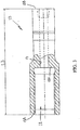
- Fig. 1 shows a drill rod according to the present invention in side view.
- Fig. 2 shows a part before welding.
- Fig. 3 shows another part, partly in cross-section, before welding.
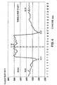
- Fig. 4 shows a chart regarding core hardness distribution in the longitudinal direction of a drill rod according to the present invention around the melting line.
- a drill rod 10 comprising a first rod part 11, a second rod part 12 and a third rod part 13. Said parts are at least partly cylindrical.
- the drill rod 10 has a through-going duct for transportation of flushing medium such as water, air or a mixture of the same.
- the first rod part 11 according to Fig. 2 comprises a free end 11A, an opposite end 11B, an inner duct 14, and an externally threaded part 15 near the free end.
- the free end has a stop face 11C for transfer of shock waves.
- the externally threaded part 15 is entirely or partly hardened by heat treatment.
- the first rod part 11 has a largest length L1, which is 0,2-0,5 m. In a preferred embodiment, the length L1 is 0,27 m.
- the externally threaded part 15 is hardened to a hardness in the interval of 440 HV1 to 750 HV1.
- the first rod part 11 is preferably tempered and high-frequency hardened before welding to another part.
- the second rod part 12 consists of a round rod 12A having an inner duct 16, see Fig. 1 .
- the rod part 12 has end surfaces 12B and 12C, each one of which has a diameter having substantially the same dimensions as the one of the opposite end 11B of the first rod part 11.
- the second rod part 12 has a largest length L2, which is 1-5 m. In a preferred embodiment, the length L2 is 3,8 m.
- the second rod part 12 does not need to be heat-treated before welding to another part.
- the steel, which the second rod part is manufactured from, has a core hardness that is in the interval of 350 HV1 to 440 HV1.
- the third rod part 13 comprises a free end 13A, an opposite end 13B, an inner duct 17, and an internally threaded recess or part 18 associated to the inner duct of the second rod part near the free end 13A.
- the internally threaded part 18 is entirely or partly hardened by heat treatment.
- the third rod part 13 has a largest length L3, which is 0,2-0,5 m. In a preferred embodiment, the length L3 is equal to the length L1, for instance 0,27 m.
- the recess 18 has a bottom surface 18A intended to co-operate with a stop face 11C of an associated second drill rod, not shown, in order to transfer shock waves at percussive rock drilling.
- the internally threaded part is hardened to hardness in the interval of 440 HV1 to 750 HV1.
- the third rod part 13 is heat-treated preferably by acierage and direct hardening by means of air-cooling before welding to another part.
- the opposite ends 11B and 13B of the rod parts 11 and 13, respectively, are friction welded together with each other or the second rod part 12 in a conventional way in order to define weld zones or melting lines 19 and 20 at the respective opposite ends 11B and 13B.
- the weld zones have not been heat-treated, for example annealed, after welding.
- Each weld zone 19, 20 has at least partly higher hardness value than the core hardness of the steel which the second rod part 12 is manufactured from.
- the readily usable rod comprises soft zones at each side of the weld zone 19, 20.
- the hardness of the soft zone is more than 300 HV1 but less than 360 HV1 at each side of the weld zone 19, 20.
- the drill rod comprises two welds, spaced-apart from each other in the axial direction of the rod with a distance of 1-5 m.
- the largest length L of the completed drill rod is in the interval of 3-10 m, preferably around 4,5 m.
- Fig. 4 shows a chart regarding core hardness distribution in the longitudinal direction of a drill rod according to the present invention around the melting line.
- HV1 is Vicker's hardness with a load of 1 kg.
- the melting line may be defined as the bonding zone between two components and is shown by means of a vertical dashed line in Fig. 4 .
- the melting line may be regarded as having a width of 0,3-3 mm.
- the weld zone includes the melting line and is preferably 7-11 mm in the axial direction.
- the core hardness profile is shown by means of an unbroken line and the hardness increases significantly from the starting material in the direction of the melting line. In the chart, the structure that the respective part has after the friction welding is given.
- the rod 12 is only rolled and contains about 50 % bainite B and about 50 % martensite M.
- the threaded part or the rod part 11 or 13 is preferably tempered but the opposite end thereof consists of about 50 % bainite and about 50 % martensite.
- the weld zone 19, 20 On both sides (about 4 mm) of the melting line, the weld zone 19, 20 has essentially (more than 50 %) non-annealed, martensitic structure and high hardness (just below 500 HV1).
- Axially next to the non-annealed, martensitic structure there is a structure essentially consisting of bainite and perlite P.
- the later structure has a relatively low hardness around 320 HV1.
- the drill rod 10 according to the present invention has at tests turned out to obtain production results equivalent to those of heat-treated conventional drill rods.
- the method for manufacturing the drill rod comprises the following steps: provide a first rod part 11 with an inner duct 14, a free end 11A, an opposite end 11B and an externally threaded part 18 near the free end, the externally threaded part entirely or partly being hardened by heat treatment; provide an additional rod part 13 having an inner duct 17, a free end 13A, an opposite end 13B, and an internally threaded part 18 associated to the inner duct of the additional rod part, the internally threaded part entirely or partly being hardened by heat treatment; wherein the opposite ends of the rod parts are welded together in order to define a weld zone next to the opposite ends, the drill rod being intended to be used without the weld zone having been heat-treated after welding.
- the rod parts 11 are friction welded to another hollow rod part 12.
- each weld zone is then turned, so that the radially outer surface of the weld zone becomes smooth and somewhat concave.
- the drill rod is welded preferably at two points, spaced-apart from each other by at least one metre in the axial direction of the rod.
- the drill rod is made from steel having a certain core hardness.
- the weld zone is given the same hardness value as, or higher hardness value than, the core hardness of the steel in the hollow rod part.
- the externally threaded part and the internally threaded part are hardened to hardness in the interval of 440 HV1 to 750 HV1.
- the rod is preferably manufactured from at least three separate, readily machined parts, thus there are at least two weld zones after friction welding.
- the intermediate storage of those separate parts they can be combined in different ways to provide prerequisites for a quick and flexible production of different shapes of rods.
- the size of the stock of readily usable rods can be reduced and thereby reducing the costs for storage and the risk for obsolete products.
Landscapes
- Engineering & Computer Science (AREA)
- Mining & Mineral Resources (AREA)
- Life Sciences & Earth Sciences (AREA)
- Geology (AREA)
- Chemical & Material Sciences (AREA)
- Mechanical Engineering (AREA)
- Physics & Mathematics (AREA)
- General Life Sciences & Earth Sciences (AREA)
- Fluid Mechanics (AREA)
- Geochemistry & Mineralogy (AREA)
- Environmental & Geological Engineering (AREA)
- Thermal Sciences (AREA)
- Crystallography & Structural Chemistry (AREA)
- Materials Engineering (AREA)
- Metallurgy (AREA)
- Organic Chemistry (AREA)
- Earth Drilling (AREA)
- Drilling Tools (AREA)
- Heat Treatment Of Articles (AREA)
Claims (6)
- Tige de forage destinée à un forage de roche par percussion comprenant :une première partie de tige (11) comprenant une extrémité libre (11A), une extrémité opposée (11B), un conduit intérieur (14), et une partie filetée sur l'extérieur (15) près de l'extrémité libre, la partie filetée sur l'extérieur étant entièrement ou partiellement durcie par traitement thermique ;une partie de tige supplémentaire (13) comprenant une extrémité libre (13A), une extrémité opposée (13B), un conduit intérieur (17), et une partie filetée sur l'intérieur (18) près de l'extrémité libre (13A) de la deuxième partie de tige, la partie filetée sur l'intérieur (18) étant entièrement ou partiellement durcie par traitement thermique ; caractérisée en ce que les extrémités opposées (11B, 13B) des parties de tige sont soudées ensemble directement l'une sur l'autre ou avec une partie de tige creuse intermédiaire (12) de sorte à définir une zone soudée à côté de chaque extrémité opposée, et en ce que la zone soudée (19, 20) présente une structure sensiblement martensitique non recuite et en ce que la partie filetée à l'extérieur (15) et la partie filetée à l'intérieur (18) sont durcies jusqu'à atteindre une dureté comprise dans l'intervalle allant de 440 HV1 à 750 HV1.
- Tige de forage selon la revendication 1, la tige de forage (10) comprenant deux soudures (19, 20), espacées l'une de l'autre dans la direction axiale de la tige par au moins un mètre.
- Tige de forage selon la revendication 1 ou 2, les extrémités opposées (11B, 13B) des parties de tige étant soudées par soudage par friction.
- Tige de forage selon la revendication 1, la tige de forage (10) étant fabriquée à partir d'un acier présentant une certaine dureté de noyau, la zone soudée (19, 20) ayant au moins partiellement une valeur de dureté supérieure à la dureté de noyau dans la tige de forage.
- Procédé de fabrication d'une tige de forage destinée à un forage de roche par percussion comprenant les étapes suivantes consistant à :fournir une première partie de tige (11) ayant une extrémité libre (11A), une extrémité opposée (11B), un conduit intérieur (14), et une partie filetée sur l'extérieur (15) près de l'extrémité libre, la partie filetée sur l'extérieur étant entièrement ou partiellement durcie par traitement thermique ;fournir une partie de tige supplémentaire (13) ayant une extrémité libre (13A), une extrémité opposée (13B), un conduit intérieur (17), et une partie filetée sur l'intérieur (18) près de l'extrémité libre (13A) de la partie de tige supplémentaire, la partie filetée sur l'intérieur (18) étant entièrement ou partiellement durcie par traitement thermique ; caractérisé en ce que les extrémités opposées (11B, 13B) des parties de tige (11, 13) sont soudées ensemble directement l'une sur l'autre ou avec une partie de tige creuse intermédiaire (12) de sorte à définir une zone soudée (19, 20) à côté des extrémités opposées (11B, 13B), et en ce que aucun autre traitement thermique de la tige de forage (10) n'est réalisé après soudage de telle sorte que la tige de forage (10) dans la zone soudée (19, 20) conserve une structure sensiblement martensitique non recuite, et en ce que la tige de forage (10) est constituée d'acier ayant une certaine dureté de noyau, la zone soudée (19, 20) étant amenée au moins partiellement à une valeur de dureté supérieure à la dureté de noyau dans l'acier qui constitue la partie de tige creuse (12), et la partie filetée à l'extérieur (15) et la partie filetée à l'intérieur (18) sont durcies jusqu'à atteindre une dureté comprise dans l'intervalle allant de 440 HV1 à 750 HV1.
- Procédé selon la revendication 5, la tige de forage (10) étant soudée en deux points, espacés l'un de l'autre dans la direction axiale de la tige par au moins un mètre.
Applications Claiming Priority (3)
| Application Number | Priority Date | Filing Date | Title |
|---|---|---|---|
| SE0202814A SE524322C2 (sv) | 2002-09-24 | 2002-09-24 | Borrstång och metod för att tillverka denna |
| EP03798631.2A EP1546504B1 (fr) | 2002-09-24 | 2003-09-22 | Tige de forage et son procede de production |
| PCT/SE2003/001476 WO2004029403A1 (fr) | 2002-09-24 | 2003-09-22 | Tige de forage et son procede de production |
Related Parent Applications (2)
| Application Number | Title | Priority Date | Filing Date |
|---|---|---|---|
| EP03798631.2A Division EP1546504B1 (fr) | 2002-09-24 | 2003-09-22 | Tige de forage et son procede de production |
| EP03798631.2A Division-Into EP1546504B1 (fr) | 2002-09-24 | 2003-09-22 | Tige de forage et son procede de production |
Publications (2)
| Publication Number | Publication Date |
|---|---|
| EP2796573A1 EP2796573A1 (fr) | 2014-10-29 |
| EP2796573B1 true EP2796573B1 (fr) | 2018-11-14 |
Family
ID=20289070
Family Applications (2)
| Application Number | Title | Priority Date | Filing Date |
|---|---|---|---|
| EP14175519.9A Expired - Lifetime EP2796573B1 (fr) | 2002-09-24 | 2003-09-22 | Tige de forage et son procédé de production |
| EP03798631.2A Expired - Lifetime EP1546504B1 (fr) | 2002-09-24 | 2003-09-22 | Tige de forage et son procede de production |
Family Applications After (1)
| Application Number | Title | Priority Date | Filing Date |
|---|---|---|---|
| EP03798631.2A Expired - Lifetime EP1546504B1 (fr) | 2002-09-24 | 2003-09-22 | Tige de forage et son procede de production |
Country Status (9)
| Country | Link |
|---|---|
| US (1) | US7571779B2 (fr) |
| EP (2) | EP2796573B1 (fr) |
| KR (1) | KR101017873B1 (fr) |
| AU (1) | AU2003265040A1 (fr) |
| CA (1) | CA2498385C (fr) |
| RU (1) | RU2312967C2 (fr) |
| SE (1) | SE524322C2 (fr) |
| WO (1) | WO2004029403A1 (fr) |
| ZA (1) | ZA200502377B (fr) |
Families Citing this family (13)
| Publication number | Priority date | Publication date | Assignee | Title |
|---|---|---|---|---|
| SE525664C2 (sv) * | 2003-05-16 | 2005-03-29 | Atlas Copco Secoroc Ab | Skarvstång samt förfarande för framställning av denna |
| SE531459C2 (sv) * | 2006-05-17 | 2009-04-14 | Sandvik Intellectual Property | Hondel samt förfarande för tillverkning av hondelar |
| CN201301670Y (zh) | 2008-04-23 | 2009-09-02 | 长年Tm公司 | 双钢冲击钻杆 |
| RU2399744C1 (ru) * | 2009-06-03 | 2010-09-20 | Игорь Давидович Шапошников | Бурильная штанга коническая |
| US20110079446A1 (en) * | 2009-10-05 | 2011-04-07 | Baker Hughes Incorporated | Earth-boring tools and components thereof and methods of attaching components of an earth-boring tool |
| DE102010043837A1 (de) * | 2010-11-12 | 2012-05-16 | Hilti Aktiengesellschaft | Schlagwerkskörper, Schlagwerk und Handwerkzeugmaschine mit einem Schlagwerk |
| MX337309B (es) * | 2011-03-14 | 2016-02-25 | Rotary Drilling Tools Usa Lp | Almohadilla de desgaste integral y metodo. |
| FR2976015B1 (fr) * | 2011-05-30 | 2014-11-07 | Vam Drilling France | Composant tubulaire pour l'exploration d'un puits d'hydrocarbures |
| CN103143901B (zh) * | 2013-04-03 | 2013-11-20 | 江苏拓海煤矿钻探机械有限公司 | 高强度煤层抽采瓦斯用三棱型钻杆的焊接方法 |
| EP2845993B1 (fr) * | 2013-09-09 | 2018-01-10 | Sandvik Intellectual Property AB | Couplage de tiges de forage à percussion à transmission d'énergie efficace |
| EP2845992B1 (fr) | 2013-09-09 | 2016-01-13 | Sandvik Intellectual Property AB | Train de tiges de forage avec couplage résistant à la flexion |
| EP2868860B1 (fr) * | 2013-09-09 | 2016-01-13 | Sandvik Intellectual Property AB | Composant de train de forage |
| US11945087B2 (en) | 2019-03-29 | 2024-04-02 | Tien-I Industrial Co., Ltd. | Impact tool head |
Family Cites Families (13)
| Publication number | Priority date | Publication date | Assignee | Title |
|---|---|---|---|---|
| US3784238A (en) * | 1971-05-17 | 1974-01-08 | Smith International | Intermediate drill stem |
| US3773359A (en) * | 1971-06-24 | 1973-11-20 | Smith International | Intermediate drill stem |
| US4181845A (en) * | 1977-07-11 | 1980-01-01 | Smith International, Inc. | Apparatus for tempering the weld between a tool joint connector and a drill pipe tube |
| CA1082955A (fr) * | 1978-07-21 | 1980-08-05 | James A. Minton | Methode et appareil pour ameliorer les proprietes mecaniques de produits tubulaires soudes par rapprochement |
| FI68293B (fi) * | 1982-11-30 | 1985-04-30 | Airam Ab Oy | Foerfarande i laonghaolbergborrning och borrstaongsystem |
| DE3825992A1 (de) * | 1988-07-28 | 1990-02-01 | Mannesmann Ag | Bohrrohr |
| SE506178C2 (sv) | 1996-01-22 | 1997-11-17 | Sandvik Ab | Friktionssvetsad produkt för bergborrning samt förfarande för tillverkning av produkten |
| SE507440C2 (sv) * | 1996-06-20 | 1998-06-08 | Sandvik Ab | Friktionssvetsad borrstång samt förfarande för tillverkning av borrstången |
| SE507439C2 (sv) * | 1996-06-24 | 1998-06-08 | Sandvik Ab | Friktionssvetsad borrstång samt förfarande för tillverkning av borrstången |
| US5988301A (en) | 1997-06-20 | 1999-11-23 | Sandvik Ab | Drill rod and method for its manufacture |
| WO2001042615A2 (fr) | 1999-12-10 | 2001-06-14 | Ingersoll-Rand Company | Tige de sonde a sections selectivement trempees |
| SE520893C2 (sv) * | 2002-02-21 | 2003-09-09 | Sandvik Ab | Element för slående bergborrning, innefattande åtminstone en gänga |
| SE524155C2 (sv) * | 2002-05-22 | 2004-07-06 | Atlas Copco Secoroc Ab | Gängförband för borrsträng för slående bergborrning |
-
2002
- 2002-09-24 SE SE0202814A patent/SE524322C2/sv unknown
-
2003
- 2003-09-22 EP EP14175519.9A patent/EP2796573B1/fr not_active Expired - Lifetime
- 2003-09-22 AU AU2003265040A patent/AU2003265040A1/en not_active Abandoned
- 2003-09-22 CA CA2498385A patent/CA2498385C/fr not_active Expired - Lifetime
- 2003-09-22 EP EP03798631.2A patent/EP1546504B1/fr not_active Expired - Lifetime
- 2003-09-22 KR KR1020057004939A patent/KR101017873B1/ko not_active Expired - Lifetime
- 2003-09-22 RU RU2005112237/03A patent/RU2312967C2/ru active
- 2003-09-22 WO PCT/SE2003/001476 patent/WO2004029403A1/fr not_active Ceased
-
2005
- 2005-03-22 ZA ZA2005/02377A patent/ZA200502377B/en unknown
- 2005-03-24 US US11/087,799 patent/US7571779B2/en not_active Expired - Lifetime
Non-Patent Citations (1)
| Title |
|---|
| None * |
Also Published As
| Publication number | Publication date |
|---|---|
| ZA200502377B (en) | 2005-11-30 |
| EP2796573A1 (fr) | 2014-10-29 |
| SE0202814D0 (sv) | 2002-09-24 |
| EP1546504A1 (fr) | 2005-06-29 |
| CA2498385C (fr) | 2012-01-10 |
| KR20050053684A (ko) | 2005-06-08 |
| CA2498385A1 (fr) | 2004-04-08 |
| US7571779B2 (en) | 2009-08-11 |
| EP1546504B1 (fr) | 2015-01-21 |
| SE0202814L (sv) | 2004-03-25 |
| AU2003265040A1 (en) | 2004-04-19 |
| KR101017873B1 (ko) | 2011-03-04 |
| WO2004029403A1 (fr) | 2004-04-08 |
| RU2005112237A (ru) | 2005-09-20 |
| SE524322C2 (sv) | 2004-07-27 |
| US20050217901A1 (en) | 2005-10-06 |
| RU2312967C2 (ru) | 2007-12-20 |
Similar Documents
| Publication | Publication Date | Title |
|---|---|---|
| EP2796573B1 (fr) | Tige de forage et son procédé de production | |
| AU612268B2 (en) | Compound steel work pieces and method for their production | |
| AU2011271660B2 (en) | Integral wear pad and method | |
| US6095266A (en) | Drill rod and method for its manufacturer | |
| WO1996002676A8 (fr) | Elements de charpente profiles a froid en acier extremement resistant | |
| EP1476634B1 (fr) | Element de forage permettant de forer des roches et son procede de fabrication | |
| US4886710A (en) | Mining/construction tool bit having bit body fabricated from Mn-B steel alloy composition | |
| EP3027333B1 (fr) | Centreur tubulaire roulé | |
| WO2001042615A2 (fr) | Tige de sonde a sections selectivement trempees | |
| US5988301A (en) | Drill rod and method for its manufacture | |
| CA2257488A1 (fr) | Tige de forage soudee par friction et procede de fabrication de cette tige | |
| JP2512984B2 (ja) | スプリング用継目無鋼管の製造方法 | |
| EP1625277B1 (fr) | Barre de liaison utilisee pour le forage de roches, et son procede de production | |
| US5112411A (en) | Process of making mining/construction tool bit body fabricated from MN/B steel alloy composition | |
| US20020104213A1 (en) | Process for manufacturing a cylindrical hollow body and hollow body made thereby | |
| EP3791077B1 (fr) | Procédé pour assurer une défaillance contrôlée d'une barre de boulon d'ancrage | |
| EP0303845B1 (fr) | Arbre creux et procédé pour sa fabrication | |
| JPH07148729A (ja) | ダイヤモンドコアビット | |
| WO2003097885A1 (fr) | Element de forage de roche et procede | |
| EP3560626B1 (fr) | Procédé de fabrication d'un essieu monobloc | |
| GB2150178A (en) | Leg member for a jack-up type rig and a method of manufacturing the same | |
| SE523940C2 (sv) | Borrelement för bergborrning och en metod för att tillverka borrelementet | |
| JP2002520575A (ja) | 吸収体及び制御棒 | |
| Yamashita et al. | High-adhesion/high-strength deformed steel bar and method for manufacturing the same | |
| ZA200405906B (en) | Drill member for rock drilling and a method for manufacturing the drill member |
Legal Events
| Date | Code | Title | Description |
|---|---|---|---|
| PUAI | Public reference made under article 153(3) epc to a published international application that has entered the european phase |
Free format text: ORIGINAL CODE: 0009012 |
|
| 17P | Request for examination filed |
Effective date: 20140703 |
|
| AC | Divisional application: reference to earlier application |
Ref document number: 1546504 Country of ref document: EP Kind code of ref document: P |
|
| AK | Designated contracting states |
Kind code of ref document: A1 Designated state(s): AT BE BG CH CY CZ DE DK EE ES FI FR GB GR HU IE IT LI LU MC NL PT RO SE SI SK TR |
|
| RIN1 | Information on inventor provided before grant (corrected) |
Inventor name: HEDLUND, ANN-CATTHRIN Inventor name: LARSSON, KENNETH |
|
| RIN1 | Information on inventor provided before grant (corrected) |
Inventor name: LARSSON, KENNETH Inventor name: HEDLUND, ANN-CATTHRIN |
|
| R17P | Request for examination filed (corrected) |
Effective date: 20150429 |
|
| RBV | Designated contracting states (corrected) |
Designated state(s): AT BE BG CH CY CZ DE DK EE ES FI FR GB GR HU IE IT LI LU MC NL PT RO SE SI SK TR |
|
| GRAP | Despatch of communication of intention to grant a patent |
Free format text: ORIGINAL CODE: EPIDOSNIGR1 |
|
| STAA | Information on the status of an ep patent application or granted ep patent |
Free format text: STATUS: GRANT OF PATENT IS INTENDED |
|
| INTG | Intention to grant announced |
Effective date: 20180531 |
|
| GRAS | Grant fee paid |
Free format text: ORIGINAL CODE: EPIDOSNIGR3 |
|
| GRAA | (expected) grant |
Free format text: ORIGINAL CODE: 0009210 |
|
| STAA | Information on the status of an ep patent application or granted ep patent |
Free format text: STATUS: THE PATENT HAS BEEN GRANTED |
|
| AC | Divisional application: reference to earlier application |
Ref document number: 1546504 Country of ref document: EP Kind code of ref document: P |
|
| AK | Designated contracting states |
Kind code of ref document: B1 Designated state(s): AT BE BG CH CY CZ DE DK EE ES FI FR GB GR HU IE IT LI LU MC NL PT RO SE SI SK TR |
|
| RIN1 | Information on inventor provided before grant (corrected) |
Inventor name: HEDLUND, ANN-CATHRIN Inventor name: LARSSON, KENNETH |
|
| REG | Reference to a national code |
Ref country code: CH Ref legal event code: EP Ref country code: AT Ref legal event code: REF Ref document number: 1064901 Country of ref document: AT Kind code of ref document: T Effective date: 20181115 |
|
| REG | Reference to a national code |
Ref country code: DE Ref legal event code: R096 Ref document number: 60351639 Country of ref document: DE |
|
| REG | Reference to a national code |
Ref country code: IE Ref legal event code: FG4D |
|
| REG | Reference to a national code |
Ref country code: SE Ref legal event code: TRGR |
|
| REG | Reference to a national code |
Ref country code: NL Ref legal event code: MP Effective date: 20181114 |
|
| PG25 | Lapsed in a contracting state [announced via postgrant information from national office to epo] |
Ref country code: BG Free format text: LAPSE BECAUSE OF FAILURE TO SUBMIT A TRANSLATION OF THE DESCRIPTION OR TO PAY THE FEE WITHIN THE PRESCRIBED TIME-LIMIT Effective date: 20190214 Ref country code: ES Free format text: LAPSE BECAUSE OF FAILURE TO SUBMIT A TRANSLATION OF THE DESCRIPTION OR TO PAY THE FEE WITHIN THE PRESCRIBED TIME-LIMIT Effective date: 20181114 |
|
| PG25 | Lapsed in a contracting state [announced via postgrant information from national office to epo] |
Ref country code: PT Free format text: LAPSE BECAUSE OF FAILURE TO SUBMIT A TRANSLATION OF THE DESCRIPTION OR TO PAY THE FEE WITHIN THE PRESCRIBED TIME-LIMIT Effective date: 20190314 Ref country code: GR Free format text: LAPSE BECAUSE OF FAILURE TO SUBMIT A TRANSLATION OF THE DESCRIPTION OR TO PAY THE FEE WITHIN THE PRESCRIBED TIME-LIMIT Effective date: 20190215 Ref country code: NL Free format text: LAPSE BECAUSE OF FAILURE TO SUBMIT A TRANSLATION OF THE DESCRIPTION OR TO PAY THE FEE WITHIN THE PRESCRIBED TIME-LIMIT Effective date: 20181114 |
|
| PG25 | Lapsed in a contracting state [announced via postgrant information from national office to epo] |
Ref country code: DK Free format text: LAPSE BECAUSE OF FAILURE TO SUBMIT A TRANSLATION OF THE DESCRIPTION OR TO PAY THE FEE WITHIN THE PRESCRIBED TIME-LIMIT Effective date: 20181114 Ref country code: CZ Free format text: LAPSE BECAUSE OF FAILURE TO SUBMIT A TRANSLATION OF THE DESCRIPTION OR TO PAY THE FEE WITHIN THE PRESCRIBED TIME-LIMIT Effective date: 20181114 |
|
| REG | Reference to a national code |
Ref country code: DE Ref legal event code: R097 Ref document number: 60351639 Country of ref document: DE |
|
| PG25 | Lapsed in a contracting state [announced via postgrant information from national office to epo] |
Ref country code: RO Free format text: LAPSE BECAUSE OF FAILURE TO SUBMIT A TRANSLATION OF THE DESCRIPTION OR TO PAY THE FEE WITHIN THE PRESCRIBED TIME-LIMIT Effective date: 20181114 Ref country code: SK Free format text: LAPSE BECAUSE OF FAILURE TO SUBMIT A TRANSLATION OF THE DESCRIPTION OR TO PAY THE FEE WITHIN THE PRESCRIBED TIME-LIMIT Effective date: 20181114 Ref country code: EE Free format text: LAPSE BECAUSE OF FAILURE TO SUBMIT A TRANSLATION OF THE DESCRIPTION OR TO PAY THE FEE WITHIN THE PRESCRIBED TIME-LIMIT Effective date: 20181114 |
|
| PLBE | No opposition filed within time limit |
Free format text: ORIGINAL CODE: 0009261 |
|
| STAA | Information on the status of an ep patent application or granted ep patent |
Free format text: STATUS: NO OPPOSITION FILED WITHIN TIME LIMIT |
|
| 26N | No opposition filed |
Effective date: 20190815 |
|
| PG25 | Lapsed in a contracting state [announced via postgrant information from national office to epo] |
Ref country code: SI Free format text: LAPSE BECAUSE OF FAILURE TO SUBMIT A TRANSLATION OF THE DESCRIPTION OR TO PAY THE FEE WITHIN THE PRESCRIBED TIME-LIMIT Effective date: 20181114 |
|
| PG25 | Lapsed in a contracting state [announced via postgrant information from national office to epo] |
Ref country code: TR Free format text: LAPSE BECAUSE OF FAILURE TO SUBMIT A TRANSLATION OF THE DESCRIPTION OR TO PAY THE FEE WITHIN THE PRESCRIBED TIME-LIMIT Effective date: 20181114 |
|
| REG | Reference to a national code |
Ref country code: AT Ref legal event code: UEP Ref document number: 1064901 Country of ref document: AT Kind code of ref document: T Effective date: 20181114 |
|
| PG25 | Lapsed in a contracting state [announced via postgrant information from national office to epo] |
Ref country code: MC Free format text: LAPSE BECAUSE OF FAILURE TO SUBMIT A TRANSLATION OF THE DESCRIPTION OR TO PAY THE FEE WITHIN THE PRESCRIBED TIME-LIMIT Effective date: 20181114 |
|
| REG | Reference to a national code |
Ref country code: CH Ref legal event code: PL |
|
| PG25 | Lapsed in a contracting state [announced via postgrant information from national office to epo] |
Ref country code: LI Free format text: LAPSE BECAUSE OF NON-PAYMENT OF DUE FEES Effective date: 20190930 Ref country code: LU Free format text: LAPSE BECAUSE OF NON-PAYMENT OF DUE FEES Effective date: 20190922 Ref country code: CH Free format text: LAPSE BECAUSE OF NON-PAYMENT OF DUE FEES Effective date: 20190930 |
|
| REG | Reference to a national code |
Ref country code: BE Ref legal event code: MM Effective date: 20190930 |
|
| PG25 | Lapsed in a contracting state [announced via postgrant information from national office to epo] |
Ref country code: BE Free format text: LAPSE BECAUSE OF NON-PAYMENT OF DUE FEES Effective date: 20190930 |
|
| PG25 | Lapsed in a contracting state [announced via postgrant information from national office to epo] |
Ref country code: FR Free format text: LAPSE BECAUSE OF NON-PAYMENT OF DUE FEES Effective date: 20190930 |
|
| PG25 | Lapsed in a contracting state [announced via postgrant information from national office to epo] |
Ref country code: CY Free format text: LAPSE BECAUSE OF FAILURE TO SUBMIT A TRANSLATION OF THE DESCRIPTION OR TO PAY THE FEE WITHIN THE PRESCRIBED TIME-LIMIT Effective date: 20181114 |
|
| PG25 | Lapsed in a contracting state [announced via postgrant information from national office to epo] |
Ref country code: HU Free format text: LAPSE BECAUSE OF FAILURE TO SUBMIT A TRANSLATION OF THE DESCRIPTION OR TO PAY THE FEE WITHIN THE PRESCRIBED TIME-LIMIT; INVALID AB INITIO Effective date: 20030922 |
|
| PGFP | Annual fee paid to national office [announced via postgrant information from national office to epo] |
Ref country code: SE Payment date: 20220811 Year of fee payment: 20 Ref country code: IT Payment date: 20220811 Year of fee payment: 20 Ref country code: IE Payment date: 20220809 Year of fee payment: 20 Ref country code: GB Payment date: 20220804 Year of fee payment: 20 Ref country code: FI Payment date: 20220909 Year of fee payment: 20 Ref country code: DE Payment date: 20220803 Year of fee payment: 20 Ref country code: AT Payment date: 20220825 Year of fee payment: 20 |
|
| REG | Reference to a national code |
Ref country code: DE Ref legal event code: R071 Ref document number: 60351639 Country of ref document: DE |
|
| REG | Reference to a national code |
Ref country code: GB Ref legal event code: PE20 Expiry date: 20230921 |
|
| REG | Reference to a national code |
Ref country code: IE Ref legal event code: MK9A |
|
| PG25 | Lapsed in a contracting state [announced via postgrant information from national office to epo] |
Ref country code: GB Free format text: LAPSE BECAUSE OF EXPIRATION OF PROTECTION Effective date: 20230921 |
|
| REG | Reference to a national code |
Ref country code: SE Ref legal event code: EUG |
|
| REG | Reference to a national code |
Ref country code: AT Ref legal event code: MK07 Ref document number: 1064901 Country of ref document: AT Kind code of ref document: T Effective date: 20230922 |
|
| PG25 | Lapsed in a contracting state [announced via postgrant information from national office to epo] |
Ref country code: IE Free format text: LAPSE BECAUSE OF EXPIRATION OF PROTECTION Effective date: 20230922 |