EP2800960B1 - Ionisierungsmessgerät für hochdruckoperationen - Google Patents
Ionisierungsmessgerät für hochdruckoperationen Download PDFInfo
- Publication number
- EP2800960B1 EP2800960B1 EP13746239.6A EP13746239A EP2800960B1 EP 2800960 B1 EP2800960 B1 EP 2800960B1 EP 13746239 A EP13746239 A EP 13746239A EP 2800960 B1 EP2800960 B1 EP 2800960B1
- Authority
- EP
- European Patent Office
- Prior art keywords
- ionization
- electron source
- collector electrode
- collector
- electrons
- Prior art date
- Legal status (The legal status is an assumption and is not a legal conclusion. Google has not performed a legal analysis and makes no representation as to the accuracy of the status listed.)
- Active
Links
Images


Classifications
-
- G—PHYSICS
- G01—MEASURING; TESTING
- G01L—MEASURING FORCE, STRESS, TORQUE, WORK, MECHANICAL POWER, MECHANICAL EFFICIENCY, OR FLUID PRESSURE
- G01L21/00—Vacuum gauges
- G01L21/30—Vacuum gauges by making use of ionisation effects
- G01L21/32—Vacuum gauges by making use of ionisation effects using electric discharge tubes with thermionic cathodes
-
- G—PHYSICS
- G01—MEASURING; TESTING
- G01L—MEASURING FORCE, STRESS, TORQUE, WORK, MECHANICAL POWER, MECHANICAL EFFICIENCY, OR FLUID PRESSURE
- G01L19/00—Details of, or accessories for, apparatus for measuring steady or quasi-steady pressure of a fluent medium insofar as such details or accessories are not special to particular types of pressure gauges
- G01L19/06—Means for preventing overload or deleterious influence of the measured medium on the measuring device or vice versa
- G01L19/0627—Protection against aggressive medium in general
-
- G—PHYSICS
- G01—MEASURING; TESTING
- G01L—MEASURING FORCE, STRESS, TORQUE, WORK, MECHANICAL POWER, MECHANICAL EFFICIENCY, OR FLUID PRESSURE
- G01L21/00—Vacuum gauges
- G01L21/30—Vacuum gauges by making use of ionisation effects
-
- H—ELECTRICITY
- H01—ELECTRIC ELEMENTS
- H01J—ELECTRIC DISCHARGE TUBES OR DISCHARGE LAMPS
- H01J1/00—Details of electrodes, of magnetic control means, of screens, or of the mounting or spacing thereof, common to two or more basic types of discharge tubes or lamps
- H01J1/52—Screens for shielding; Guides for influencing the discharge; Masks interposed in the electron stream
-
- H—ELECTRICITY
- H01—ELECTRIC ELEMENTS
- H01J—ELECTRIC DISCHARGE TUBES OR DISCHARGE LAMPS
- H01J41/00—Discharge tubes for measuring pressure of introduced gas or for detecting presence of gas; Discharge tubes for evacuation by diffusion of ions
- H01J41/02—Discharge tubes for measuring pressure of introduced gas or for detecting presence of gas
- H01J41/04—Discharge tubes for measuring pressure of introduced gas or for detecting presence of gas with ionisation by means of thermionic cathodes
Definitions
- Ionization gauges more specifically Bayard-Alpert (BA) ionization gauges, are the most common non-magnetic means of measuring very low pressures. The gauges have been widely used worldwide. These gauges were disclosed in 1952 in U.S. Patent No. 2,605,431 .
- a typical ionization gauge includes an electron source, an anode, and an ion collector electrode.
- the electron source is located outside of an ionization space or anode volume which is defined by a cylindrical anode screen.
- the ion collector electrode is disposed within the anode volume. Electrons travel from the electron source to and through the anode, cycle back and forth through the anode, and are consequently retained within, or nearby to, the anode.
- the electrons collide with molecules and atoms of gas that constitute the atmosphere whose pressure is desired to be measured. This contact between the electrons and the gas creates ions. The ions are attracted to the ion collector electrode, which is typically connected to ground.
- the operational lifetime of a typical ionization gauge is approximately ten years when the gauge is operated in benign environments.
- these same gauges and electron sources (cathodes) fail in minutes or hours when operated at too high a pressure or during operation in gas types that degrade the emission characteristics of the electron source.
- Sputtering is a problem when operating the ionization gauge at high pressures, such as above 10 -4 Torr. This is a problem at high pressure because there is more gas to ionize. This sputtering is caused by high energy impacts between ions and components of the ionization gauge. Ions with a high energy may impact a tungsten material that forms a collector post of the ionization gauge.
- Ejected material can travel freely to other surfaces within the line of sight of the sputtered surfaces, and can cause gauge failure by coating the cathode or by coating of the feed-through insulators of the gauge, which can result in electric leakages.
- US2011/163754 describes an ionization gauge with emission current and bias potential control.
- US2005/028602 describes an ionization gauge comprising an electron-emitting cathode made by exploiting nanotube technology.
- the present invention provides an ionization gauge according to claim 1, and a method of measuring pressure according to claim 7.
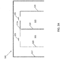
- Coating of the electron source, such as a hot filament, is facilitated by the typical arrangement, shown in FIG. 1 , of the filament and collector structures side by side to one another in a parallel arrangement, often with a large surface area of the filament facing the collector surface.
- the present ionization gauge minimizes the effects of self-sputtering on filament emission efficiency by inhibiting the sputtered atoms from finding straight paths from the collector to the electron source in the gauge.
- the ionization gauge may be used to measure pressure while controlling the location of deposits resulting from sputtering when operating at high pressure.
- the present ionization gauge has many advantages, including minimizing the exposure of the electron source to atom flux sputtered off the collector electrode and envelope surface.
- the electron source 105 such as a hot filament
- the typical arrangement, shown in FIG. 1 of the filament 105 and collector 110 structures side by side to one another in a parallel arrangement, often with a large surface area of the filament 105 facing the collector surface 110.
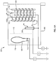
- an ionization gauge 100 of the present disclosure has an anode structure comprising a cylindrical wire grid 120 around posts 112 and 114, defining an ionization volume 121 in which electrons impact gas molecules and atoms.
- Two end grids 111a and 111b define the ends of the ionization volume 121.
- a hot cathode electron source 105 emits electrons 125, the electron source 105 being positioned at an end of the ionization volume 121.
- a collector electrode 110 collects ions formed by collisions between the electrons 125 and gas molecules and atoms, to provide a gas pressure output.
- the collector electrode 110 extends along a collector axis through the ionization volume 121, the collector axis extending through the ends of the ionization volume 121.
- the collector electrode 110 and support posts 112 and 114 protrude through the solid disk 116 that is displaced downward from end grid 111b.
- the electron source 105 can be, for example, a heated cathode filament, as shown in FIG. 2 , or a disc cathode thermionic emitter (e.g ., Kimball Physics, Inc., Wilton, NH).
- FIGS. 3A and 3B A cross-section of the upper portion of the ionization gauge 100 that includes the electron source 105 is schematically illustrated in FIGS. 3A and 3B .
- the ionization gauge 100 is based on the ionization of gas molecules and atoms in a measurement chamber 117 by a constant flow of electrons.
- the negatively charged electrons 125 shown in FIG. 3B (only shown on the left side in FIG. 3B , although electrons would similarly be on the right side) are emitted at a well-controlled selectable rate from, for example, a heated cathode 105, and can be released or accelerated toward a positively charged anode 120.
- the electrons 125 pass into and through the anode 120 and then cycle back and forth through the anode 120.
- the electrons 125 are then retained within the ionization volume of the anode 121, in part due to the potential bias on end grids 111a and 111b. In this space, the electrons 125 collide with the gas molecules and atoms to produce positively charged ions before colliding with a grid wire 120, or end grids 111a or 111b.
- the ionization volume 121 During low pressure operation, significant ionization only occurs within the anode 120, and thus the volume 121 within the anode 120 is referred to as the ionization volume 121.
- Some ionization may occur outside the ionization volume 121, in particular during high pressure operation ( e.g ., above about 10 -4 Torr), when sufficient ionization may occur for collection.
- the ions are collected by the ion collector 110.
- Collector 110 is nearly at ground potential, which is negative with respect to the positively charged anode 120. However, this arrangement is not limiting and collector 110 may have various potential differences with respect to the anode 120. See Application No. 12/860,050 published as US 2011/0062961 A1 .
- the rate that positive ions are formed is related to the density of the gas in the gauge 100.
- this signal from the collector electrode 110 is detected by an ammeter 135, which is calibrated in units of pressure, for all pressure readings.
- sputtered atoms from collector 110 that are typically ejected along paths that are perpendicular to the collector 110, are unlikely to deposit on filament 105, because filament 105 is positioned at an end of the ionization volume 121, out of a line of sight perpendicular to the collector electrode 110, and no longer alongside collector 110, in contrast to the arrangement shown in FIG. 1 .
- the use of a hot cathode filament as the electron source 105 in the geometry shown in FIG. 2 enables high pressure operation of the ionization gauge 100.
- FIGS. 4A , 4B , 5A , and 5B Alternative ionization gauges outside the scope of the claims are shown in FIGS. 4A , 4B , 5A , and 5B .
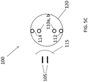
- a first shade 115 is located between the electron source 105 and the collector 110 to effectively shield the exposed filament surfaces from the effects of sputtered collector atoms.
- Electric fields direct the electrons produced by electron source 105 around the shade 115 and into the ionization volume 120.
- the electron source can, for example, be a hot cathode as shown in FIGS. 4A and 4B , or a microchannel plate. For the microchannel plate, see Application No. 12/808,983 published as US 2011/0234233 A .
- the hot cathode 105 can be a cylindrical filament shown as a single loop in FIGS.
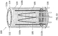
- the filament can be a double loop, as shown in FIG. 5D (where the shade 115 is not shown for clarity), or a ribbon filament, shown as top sectional views in FIGS. 5A , 5B , and 5C , the ribbon filament 105 having flat surface oriented at about 90° with respect to the collector electrode 110, such that the surface area of the filament 105 facing the collector electrode 110 is minimized.
- One of the collector electrode 110 and the electron source 105 can be located inside the anode structure 120, and the other of the collector electrode 110 and the electron source 105 can be located outside the anode structure 120. As shown in FIG.
- the ionization gauge 200 can include a first collector electrode 110a and a second collector electrode 110b located inside the anode structure 120, and, optionally, a third collector electrode 210 located outside the anode structure 120, in between the first shade 115 and the anode structure 120, for high pressure measurements of very short mean free path ions formed in measurement chamber 117.
- the ionization gauge 200 can include a single collector electrode 110 located inside the anode structure 120 and a collector electrode 210 located outside the anode structure 120, as shown in FIG. 6B .
- the collector electrode 210 is outside the ionization volume defined by the anode structure 120, but, at high pressure, ionization also occurs outside this primary ionization volume.
- FIGS. 4A , 4B , 5A , and 5B show a nude configuration of the ionization gauge 100, that is, without a surrounding gauge vessel. It is also envisioned that non-nude type ionization gauges are also possible, having an envelope 205 as shown in FIGS. 6A , 6B , discussed above and FIG. 7 , that shows a top sectional view of the ionization gauge shown in FIG. 6B . At pressures greater than about 10 -4 Torr, electrons emitted from the filament 105 have a high probability of colliding with gas atoms or molecules on the way to the anode 120.
- ions are formed outside the anode 120, they are accelerated towards the envelope 205, typically made of stainless steel, and sputtering of stainless steel is now possible.
- Some of the component atoms of stainless steel sputtered from the envelope 205 coat the back surface of the filament 105.
- the pressure continues to increase and approaches about 10 -1 Torr, the majority of ionization occurs outside the anode 120 and stainless steel wall sputtering becomes the main source of material deposited on the filament 105.
- the resulting typical deposition pattern on the filament 105 is a coating of stainless steel component atoms on the side of the filament 105 facing the envelope 205 and a coating of tungsten on the side of the filament 105 facing the collector 110.
- 6A , 6B , and 7 show specific non-nude type ionization gauges 200, wherein a second shade 119 is used to shield the electron source 105 from the effects of atoms sputtered off the envelope 205, that is, atoms sputtered off the envelope 205 are inhibited from depositing on the electron source 105.
- the first and second shades, 115 and 119 can be shaped metal plates, such as, for example, stainless steel.
- the electric potential of the shades can be the same as the cathode potential or slightly lower than the cathode potential, and therefore not subject to the sputtering problems discussed above.
- a method of measuring pressure with an ionization gauge 100 described above and shown in FIG. 2 includes emitting electrons from a hot cathode electron source 105 positioned at an end of an ionization volume 120, the electrons colliding with gas molecules and atoms inside an anode structure comprising a cylindrical mesh grid that defines the ionization volume 120.
- the method further includes collecting ions formed by collisions between the electrons and gas molecules and atoms on a collector electrode 110 to provide a gas pressure output.
- the collector electrode 110 extends along a collector axis through the ionization volume, the collector axis extending through the ends of the ionization volume.
- An alternative method of measuring pressure with an ionization gauge 200 shown in FIGS. 6A , 6B , and 7 includes emitting electrons from an electron source 105, the electrons colliding with gas molecules and atoms inside an anode structure comprising a cylindrical mesh grid that defines an ionization volume 120.
- the method further includes locating a first shade 115 outside of the ionization volume between the electron source 105 and the collector electrode 110, one of the collector electrode 110 and the electron source 105 being located inside the anode structure 120, and the other of the collector electrode 110 and the electron source 105 being located outside the anode structure 120, and collecting ions formed by collisions between the electrons and gas molecules and atoms on the collector electrode 110 to provide a gas pressure output.
- the method can further include locating a first and a second collector electrode (110a and 110b, respectively) inside the anode structure 120 and, additionally, the method can further include locating a third collector electrode 210 outside the anode structure 120, in between the first shade 115 and the anode structure 120, as shown in FIG. 6A .
- the method can further include locating a second shade 119 between the envelope 205 and the electron source 105, such that atoms sputtered off the envelope 205 are inhibited from depositing on the electron source 105.
- the pressure can be in a range of between about 10 -1 Torr and about 10 -4 Torr.
Landscapes
- Physics & Mathematics (AREA)
- General Physics & Mathematics (AREA)
- Measuring Fluid Pressure (AREA)
Claims (14)
- Ionisierungsmessgerät zum Messen von Druck, das Folgendes umfasst:eine Anodenstruktur, die ein Gitter (111, 120) umfasst, das ein Ionisierungsvolumen definiert, in dem Elektronen auf Gasmoleküle und Atome treffen;eine heiße Kathodenelektronenquelle (105), die Elektronen emittiert; undeine Kollektorelektrode (110) zum Sammeln von Ionen, die durch Kollisionen zwischen den Elektronen und Gasmolekülen und Atomen gebildet werden, um einen Gasdruckausgang bereitzustellen, wobei die Kollektorelektrode entlang einer Kollektorachse durch das Ionisierungsvolumen verläuft; dadurch gekennzeichnet, dass die Elektronenquelle an einem Ende des Ionisierungsvolumens positioniert ist, durch das die Kollektorachse verläuft.
- Ionisierungsmessgerät nach Anspruch 1, wobei das Gitter ein zylindrisches Gitter ist.
- Ionisierungsmessgerät nach Anspruch 1 oder 2, konfiguriert zum Arbeiten in einem Druckbereich zwischen etwa 10-1 Torr und 10-4 Torr.
- Ionisierungsmessgerät nach Anspruch 1, 2 oder 3, wobei die heiße Kathodenelektronenquelle ein erhitzter Kathodenglühfaden ist.
- Ionisierungsmessgerät nach Anspruch 4, wobei der erhitzte Kathodenglühfaden zu einer Schleife geformt ist.
- Ionisierungsmessgerät nach Anspruch 1, 2 oder 3, wobei die heiße Kathodenelektronenquelle ein thermionischer Scheibenkathodenemitter ist.
- Ionisierungsmessgerät nach einem vorherigen Anspruch, das ferner einen Mantel (117) beinhaltet, der die Anodenstruktur, die Elektronenquelle und die Kollektorelektrode umgibt.
- Verfahren zum Messen von Druck mit einem Ionisierungsmessgerät, das Folgendes beinhaltet:Emittieren von Elektronen von einer heißen Kathodenelektronenquelle (105), wobei die Elektronen mit Gasmolekülen und Atomen innerhalb einer Anodenstruktur kollidieren, die ein Gitter (111, 120) umfasst, das ein Ionisierungsvolumen definiert; undSammeln von durch Kollisionen zwischen den Elektronen und Gasmolekülen und Atomen gebildeten Ionen auf einer Kollektorelektrode (110), um einen Gasdruckausgang bereitzustellen, wobei die Kollektorelektrode entlang einer Kollektorachse durch das Ionisierungsvolumen verläuft; gekennzeichnet durch Positionieren der Elektronenquelle an einem Ende des Ionisierungsvolumens, durch das die Kollektorachse verläuft.
- Verfahren nach Anspruch 8, wobei das Maschengitter ein zylindrisches Maschengitter ist.
- Verfahren nach Anspruch 8 oder 9, wobei der Druck im Bereich zwischen etwa 10-1 Torr und etwa 10-4 Torr liegt.
- Verfahren nach Anspruch 8, 9 oder 10, wobei die heiße Kathodenelektronenquelle ein erhitzter Kathodenglühfaden ist.
- Verfahren nach Anspruch 11, wobei der erhitzte Kathodenglühfaden zu einer Schleife geformt ist.
- Verfahren nach Anspruch 8, 9 oder 10, wobei die heiße Kathodenelektronenquelle ein thermionischer Scheibenkathodenemitter ist.
- Verfahren nach Anspruch 8, 9, 10, 11, 12 und 13, das ferner das Umgeben der Elektronenquelle, der Anodenstruktur und der Kollektorelektrode mit einem Mantel (117) beinhaltet.
Applications Claiming Priority (2)
| Application Number | Priority Date | Filing Date | Title |
|---|---|---|---|
| US201261596470P | 2012-02-08 | 2012-02-08 | |
| PCT/US2013/025198 WO2013119851A1 (en) | 2012-02-08 | 2013-02-07 | Ionization gauge for high pressure operation |
Publications (3)
| Publication Number | Publication Date |
|---|---|
| EP2800960A1 EP2800960A1 (de) | 2014-11-12 |
| EP2800960A4 EP2800960A4 (de) | 2015-07-08 |
| EP2800960B1 true EP2800960B1 (de) | 2018-10-31 |
Family
ID=48948021
Family Applications (1)
| Application Number | Title | Priority Date | Filing Date |
|---|---|---|---|
| EP13746239.6A Active EP2800960B1 (de) | 2012-02-08 | 2013-02-07 | Ionisierungsmessgerät für hochdruckoperationen |
Country Status (8)
| Country | Link |
|---|---|
| US (2) | US9593996B2 (de) |
| EP (1) | EP2800960B1 (de) |
| JP (1) | JP6059257B2 (de) |
| KR (1) | KR102082168B1 (de) |
| CN (1) | CN104303033B (de) |
| DK (1) | DK2800960T3 (de) |
| SG (1) | SG11201404745PA (de) |
| WO (1) | WO2013119851A1 (de) |
Families Citing this family (5)
| Publication number | Priority date | Publication date | Assignee | Title |
|---|---|---|---|---|
| EP2800960B1 (de) | 2012-02-08 | 2018-10-31 | MKS Instruments, Inc. | Ionisierungsmessgerät für hochdruckoperationen |
| US9588004B2 (en) | 2014-11-07 | 2017-03-07 | Mks Instruments, Inc. | Long lifetime cold cathode ionization vacuum gauge design |
| TWI739300B (zh) | 2015-01-15 | 2021-09-11 | 美商Mks儀器公司 | 離子化計及其製造方法 |
| JP6227836B2 (ja) * | 2015-03-23 | 2017-11-08 | 株式会社アルバック | 三極管型電離真空計 |
| TW202405424A (zh) * | 2022-04-19 | 2024-02-01 | 美商英福康公司 | 使用光電離進行過程污染物檢測的分壓力計元件及相關方法 |
Family Cites Families (26)
| Publication number | Priority date | Publication date | Assignee | Title |
|---|---|---|---|---|
| US3244990A (en) * | 1963-02-26 | 1966-04-05 | Wisconsin Alumni Res Found | Electron vacuum tube employing orbiting electrons |
| FR1403080A (fr) | 1964-05-08 | 1965-06-18 | Centre Nat Rech Scient | Dispositif de mesure de la pression atmosphérique dans une large gamme de pression |
| US3839655A (en) | 1973-08-24 | 1974-10-01 | Varian Associates | Bayard-alpert vacuum ionization tube |
| US4636680A (en) | 1983-05-24 | 1987-01-13 | Granville-Phillips Company | Vacuum gauge |
| US5387247A (en) * | 1983-10-25 | 1995-02-07 | Sorin Biomedia S.P.A. | Prosthetic device having a biocompatible carbon film thereon and a method of and apparatus for forming such device |
| US4783595A (en) * | 1985-03-28 | 1988-11-08 | The Trustees Of The Stevens Institute Of Technology | Solid-state source of ions and atoms |
| DE3628847C2 (de) | 1986-08-25 | 1995-12-14 | Max Planck Gesellschaft | Heißkathoden-Ionisationsmanometer |
| US5422573A (en) * | 1990-04-11 | 1995-06-06 | Granville-Phillips Company | Ionization gauge and method of using and calibrating same |
| US5132586A (en) * | 1991-04-04 | 1992-07-21 | The United States Of America As Represented By The Secretary Of The Navy | Microchannel electron source |
| US5304799A (en) * | 1992-07-17 | 1994-04-19 | Monitor Group, Inc. | Cycloidal mass spectrometer and ionizer for use therein |
| GB9906788D0 (en) * | 1999-03-24 | 1999-05-19 | Boc Group Plc | Vacuum gauge |
| JP2001160373A (ja) * | 1999-12-02 | 2001-06-12 | Hitachi Ltd | イオントラップ質量分析方法並びにイオントラップ質量分析計 |
| US6452338B1 (en) * | 1999-12-13 | 2002-09-17 | Semequip, Inc. | Electron beam ion source with integral low-temperature vaporizer |
| JP4493139B2 (ja) * | 2000-02-02 | 2010-06-30 | キヤノンアネルバ株式会社 | 電離真空計 |
| US6566884B2 (en) * | 2001-09-13 | 2003-05-20 | Duniway Stockroom Corporation | Ionization vacuum pressure gauge |
| JP2003173757A (ja) * | 2001-12-04 | 2003-06-20 | Nissin Electric Co Ltd | イオンビーム照射装置 |
| DE10241252B4 (de) * | 2002-09-06 | 2004-09-02 | Forschungszentrum Rossendorf E.V. | Sputterionenquelle |
| ITTO20030627A1 (it) * | 2003-08-08 | 2005-02-09 | Varian Spa | Vacuometro a ionizzazione. |
| ITTO20030626A1 (it) * | 2003-08-08 | 2005-02-09 | Varian Spa | Vacuometro a ionizzazione. |
| US7030619B2 (en) | 2004-02-19 | 2006-04-18 | Brooks Automation, Inc. | Ionization gauge |
| US7456634B2 (en) * | 2006-10-26 | 2008-11-25 | Brooks Automation, Inc. | Method and apparatus for shielding feedthrough pin insulators in an ionization gauge operating in harsh environments |
| US7497110B2 (en) * | 2007-02-28 | 2009-03-03 | Varian, Inc. | Methods and apparatus for test gas leak detection |
| US8686733B2 (en) | 2007-12-19 | 2014-04-01 | Brooks Automation, Inc. | Ionization gauge having electron multiplier cold emission source |
| CN101990630B (zh) * | 2008-02-21 | 2013-08-14 | 布鲁克机械公司 | 具有设计用于高压操作的操作参数和几何形状的电离计 |
| WO2010033427A1 (en) * | 2008-09-19 | 2010-03-25 | Brooks Automation, Inc. | Ionization gauge with emission current and bias potential control |
| EP2800960B1 (de) | 2012-02-08 | 2018-10-31 | MKS Instruments, Inc. | Ionisierungsmessgerät für hochdruckoperationen |
-
2013
- 2013-02-07 EP EP13746239.6A patent/EP2800960B1/de active Active
- 2013-02-07 US US14/377,449 patent/US9593996B2/en active Active
- 2013-02-07 KR KR1020147024871A patent/KR102082168B1/ko active Active
- 2013-02-07 SG SG11201404745PA patent/SG11201404745PA/en unknown
- 2013-02-07 CN CN201380014817.8A patent/CN104303033B/zh active Active
- 2013-02-07 WO PCT/US2013/025198 patent/WO2013119851A1/en not_active Ceased
- 2013-02-07 JP JP2014556686A patent/JP6059257B2/ja not_active Expired - Fee Related
- 2013-02-07 DK DK13746239.6T patent/DK2800960T3/en active
-
2017
- 2017-02-01 US US15/421,805 patent/US9952113B2/en active Active
Non-Patent Citations (1)
| Title |
|---|
| None * |
Also Published As
| Publication number | Publication date |
|---|---|
| CN104303033A (zh) | 2015-01-21 |
| EP2800960A4 (de) | 2015-07-08 |
| CN104303033B (zh) | 2016-08-24 |
| DK2800960T3 (en) | 2019-01-28 |
| US9593996B2 (en) | 2017-03-14 |
| US9952113B2 (en) | 2018-04-24 |
| JP2015507203A (ja) | 2015-03-05 |
| US20170146420A1 (en) | 2017-05-25 |
| JP6059257B2 (ja) | 2017-01-11 |
| KR102082168B1 (ko) | 2020-02-27 |
| KR20140127859A (ko) | 2014-11-04 |
| WO2013119851A1 (en) | 2013-08-15 |
| SG11201404745PA (en) | 2014-09-26 |
| US20150300904A1 (en) | 2015-10-22 |
| EP2800960A1 (de) | 2014-11-12 |
Similar Documents
| Publication | Publication Date | Title |
|---|---|---|
| EP2252869B1 (de) | Ionisierungsmessgerät mit für hochdruckbetrieb ausgelegten betriebsparametern und geometrie | |
| US9952113B2 (en) | Ionization gauge for high pressure operation | |
| JP5080283B2 (ja) | 真空計 | |
| US7768267B2 (en) | Ionization gauge with a cold electron source | |
| Arnold et al. | Stable and reproducible Bayard–Alpert ionization gauge | |
| US7030619B2 (en) | Ionization gauge | |
| JP6932892B2 (ja) | 三極管型電離真空計及び圧力測定方法 | |
| Bills | Causes of nonstability and nonreproducibility in widely used Bayard–Alpert ionization gauges | |
| US2937295A (en) | Ionization gauge for the measurement of low pressures | |
| JP2007529096A (ja) | 電離真空計 | |
| US7295015B2 (en) | Ionization gauge | |
| Li et al. | Vacuum science and technology for accelerator vacuum systems | |
| USRE25369E (en) | Ionization gauge for the measurement of low pressures | |
| JP2013072695A (ja) | 熱陰極電離真空計 | |
| DK2252869T3 (en) | Ionization meter with operating parameters and geometry designed for high pressure operation | |
| Schmidt | MSGC Development for HERA-B |
Legal Events
| Date | Code | Title | Description |
|---|---|---|---|
| PUAI | Public reference made under article 153(3) epc to a published international application that has entered the european phase |
Free format text: ORIGINAL CODE: 0009012 |
|
| 17P | Request for examination filed |
Effective date: 20140807 |
|
| AK | Designated contracting states |
Kind code of ref document: A1 Designated state(s): AL AT BE BG CH CY CZ DE DK EE ES FI FR GB GR HR HU IE IS IT LI LT LU LV MC MK MT NL NO PL PT RO RS SE SI SK SM TR |
|
| DAX | Request for extension of the european patent (deleted) | ||
| RA4 | Supplementary search report drawn up and despatched (corrected) |
Effective date: 20150609 |
|
| RIC1 | Information provided on ipc code assigned before grant |
Ipc: H01J 41/04 20060101ALI20150602BHEP Ipc: G01L 21/32 20060101AFI20150602BHEP |
|
| REG | Reference to a national code |
Ref country code: DE Ref legal event code: R079 Ref document number: 602013045961 Country of ref document: DE Free format text: PREVIOUS MAIN CLASS: G01L0021320000 Ipc: G01L0019060000 |
|
| GRAP | Despatch of communication of intention to grant a patent |
Free format text: ORIGINAL CODE: EPIDOSNIGR1 |
|
| STAA | Information on the status of an ep patent application or granted ep patent |
Free format text: STATUS: GRANT OF PATENT IS INTENDED |
|
| RIC1 | Information provided on ipc code assigned before grant |
Ipc: H01J 41/04 20060101ALI20180411BHEP Ipc: G01L 21/32 20060101ALI20180411BHEP Ipc: G01L 19/06 20060101AFI20180411BHEP Ipc: G01L 21/30 20060101ALI20180411BHEP Ipc: H01J 1/52 20060101ALI20180411BHEP Ipc: H01J 41/02 20060101ALI20180411BHEP |
|
| INTG | Intention to grant announced |
Effective date: 20180511 |
|
| GRAS | Grant fee paid |
Free format text: ORIGINAL CODE: EPIDOSNIGR3 |
|
| GRAA | (expected) grant |
Free format text: ORIGINAL CODE: 0009210 |
|
| STAA | Information on the status of an ep patent application or granted ep patent |
Free format text: STATUS: THE PATENT HAS BEEN GRANTED |
|
| AK | Designated contracting states |
Kind code of ref document: B1 Designated state(s): AL AT BE BG CH CY CZ DE DK EE ES FI FR GB GR HR HU IE IS IT LI LT LU LV MC MK MT NL NO PL PT RO RS SE SI SK SM TR |
|
| REG | Reference to a national code |
Ref country code: CH Ref legal event code: EP Ref country code: GB Ref legal event code: FG4D |
|
| REG | Reference to a national code |
Ref country code: AT Ref legal event code: REF Ref document number: 1059961 Country of ref document: AT Kind code of ref document: T Effective date: 20181115 |
|
| REG | Reference to a national code |
Ref country code: IE Ref legal event code: FG4D |
|
| REG | Reference to a national code |
Ref country code: DE Ref legal event code: R096 Ref document number: 602013045961 Country of ref document: DE |
|
| REG | Reference to a national code |
Ref country code: DE Ref legal event code: R082 Ref document number: 602013045961 Country of ref document: DE Representative=s name: PAGE, WHITE & FARRER GERMANY LLP, DE |
|
| REG | Reference to a national code |
Ref country code: DK Ref legal event code: T3 Effective date: 20190123 |
|
| REG | Reference to a national code |
Ref country code: NL Ref legal event code: MP Effective date: 20181031 |
|
| REG | Reference to a national code |
Ref country code: LT Ref legal event code: MG4D |
|
| REG | Reference to a national code |
Ref country code: CH Ref legal event code: NV Representative=s name: BOVARD AG PATENT- UND MARKENANWAELTE, CH |
|
| REG | Reference to a national code |
Ref country code: AT Ref legal event code: MK05 Ref document number: 1059961 Country of ref document: AT Kind code of ref document: T Effective date: 20181031 |
|
| PG25 | Lapsed in a contracting state [announced via postgrant information from national office to epo] |
Ref country code: FI Free format text: LAPSE BECAUSE OF FAILURE TO SUBMIT A TRANSLATION OF THE DESCRIPTION OR TO PAY THE FEE WITHIN THE PRESCRIBED TIME-LIMIT Effective date: 20181031 Ref country code: BG Free format text: LAPSE BECAUSE OF FAILURE TO SUBMIT A TRANSLATION OF THE DESCRIPTION OR TO PAY THE FEE WITHIN THE PRESCRIBED TIME-LIMIT Effective date: 20190131 Ref country code: ES Free format text: LAPSE BECAUSE OF FAILURE TO SUBMIT A TRANSLATION OF THE DESCRIPTION OR TO PAY THE FEE WITHIN THE PRESCRIBED TIME-LIMIT Effective date: 20181031 Ref country code: IS Free format text: LAPSE BECAUSE OF FAILURE TO SUBMIT A TRANSLATION OF THE DESCRIPTION OR TO PAY THE FEE WITHIN THE PRESCRIBED TIME-LIMIT Effective date: 20190228 Ref country code: LV Free format text: LAPSE BECAUSE OF FAILURE TO SUBMIT A TRANSLATION OF THE DESCRIPTION OR TO PAY THE FEE WITHIN THE PRESCRIBED TIME-LIMIT Effective date: 20181031 Ref country code: AT Free format text: LAPSE BECAUSE OF FAILURE TO SUBMIT A TRANSLATION OF THE DESCRIPTION OR TO PAY THE FEE WITHIN THE PRESCRIBED TIME-LIMIT Effective date: 20181031 Ref country code: HR Free format text: LAPSE BECAUSE OF FAILURE TO SUBMIT A TRANSLATION OF THE DESCRIPTION OR TO PAY THE FEE WITHIN THE PRESCRIBED TIME-LIMIT Effective date: 20181031 Ref country code: PL Free format text: LAPSE BECAUSE OF FAILURE TO SUBMIT A TRANSLATION OF THE DESCRIPTION OR TO PAY THE FEE WITHIN THE PRESCRIBED TIME-LIMIT Effective date: 20181031 Ref country code: NO Free format text: LAPSE BECAUSE OF FAILURE TO SUBMIT A TRANSLATION OF THE DESCRIPTION OR TO PAY THE FEE WITHIN THE PRESCRIBED TIME-LIMIT Effective date: 20190131 Ref country code: LT Free format text: LAPSE BECAUSE OF FAILURE TO SUBMIT A TRANSLATION OF THE DESCRIPTION OR TO PAY THE FEE WITHIN THE PRESCRIBED TIME-LIMIT Effective date: 20181031 |
|
| PG25 | Lapsed in a contracting state [announced via postgrant information from national office to epo] |
Ref country code: GR Free format text: LAPSE BECAUSE OF FAILURE TO SUBMIT A TRANSLATION OF THE DESCRIPTION OR TO PAY THE FEE WITHIN THE PRESCRIBED TIME-LIMIT Effective date: 20190201 Ref country code: RS Free format text: LAPSE BECAUSE OF FAILURE TO SUBMIT A TRANSLATION OF THE DESCRIPTION OR TO PAY THE FEE WITHIN THE PRESCRIBED TIME-LIMIT Effective date: 20181031 Ref country code: NL Free format text: LAPSE BECAUSE OF FAILURE TO SUBMIT A TRANSLATION OF THE DESCRIPTION OR TO PAY THE FEE WITHIN THE PRESCRIBED TIME-LIMIT Effective date: 20181031 Ref country code: SE Free format text: LAPSE BECAUSE OF FAILURE TO SUBMIT A TRANSLATION OF THE DESCRIPTION OR TO PAY THE FEE WITHIN THE PRESCRIBED TIME-LIMIT Effective date: 20181031 Ref country code: PT Free format text: LAPSE BECAUSE OF FAILURE TO SUBMIT A TRANSLATION OF THE DESCRIPTION OR TO PAY THE FEE WITHIN THE PRESCRIBED TIME-LIMIT Effective date: 20190301 Ref country code: AL Free format text: LAPSE BECAUSE OF FAILURE TO SUBMIT A TRANSLATION OF THE DESCRIPTION OR TO PAY THE FEE WITHIN THE PRESCRIBED TIME-LIMIT Effective date: 20181031 |
|
| PG25 | Lapsed in a contracting state [announced via postgrant information from national office to epo] |
Ref country code: IT Free format text: LAPSE BECAUSE OF FAILURE TO SUBMIT A TRANSLATION OF THE DESCRIPTION OR TO PAY THE FEE WITHIN THE PRESCRIBED TIME-LIMIT Effective date: 20181031 Ref country code: CZ Free format text: LAPSE BECAUSE OF FAILURE TO SUBMIT A TRANSLATION OF THE DESCRIPTION OR TO PAY THE FEE WITHIN THE PRESCRIBED TIME-LIMIT Effective date: 20181031 |
|
| REG | Reference to a national code |
Ref country code: DE Ref legal event code: R097 Ref document number: 602013045961 Country of ref document: DE |
|
| PG25 | Lapsed in a contracting state [announced via postgrant information from national office to epo] |
Ref country code: EE Free format text: LAPSE BECAUSE OF FAILURE TO SUBMIT A TRANSLATION OF THE DESCRIPTION OR TO PAY THE FEE WITHIN THE PRESCRIBED TIME-LIMIT Effective date: 20181031 Ref country code: SM Free format text: LAPSE BECAUSE OF FAILURE TO SUBMIT A TRANSLATION OF THE DESCRIPTION OR TO PAY THE FEE WITHIN THE PRESCRIBED TIME-LIMIT Effective date: 20181031 Ref country code: RO Free format text: LAPSE BECAUSE OF FAILURE TO SUBMIT A TRANSLATION OF THE DESCRIPTION OR TO PAY THE FEE WITHIN THE PRESCRIBED TIME-LIMIT Effective date: 20181031 Ref country code: SK Free format text: LAPSE BECAUSE OF FAILURE TO SUBMIT A TRANSLATION OF THE DESCRIPTION OR TO PAY THE FEE WITHIN THE PRESCRIBED TIME-LIMIT Effective date: 20181031 |
|
| PLBE | No opposition filed within time limit |
Free format text: ORIGINAL CODE: 0009261 |
|
| STAA | Information on the status of an ep patent application or granted ep patent |
Free format text: STATUS: NO OPPOSITION FILED WITHIN TIME LIMIT |
|
| 26N | No opposition filed |
Effective date: 20190801 |
|
| PG25 | Lapsed in a contracting state [announced via postgrant information from national office to epo] |
Ref country code: MC Free format text: LAPSE BECAUSE OF FAILURE TO SUBMIT A TRANSLATION OF THE DESCRIPTION OR TO PAY THE FEE WITHIN THE PRESCRIBED TIME-LIMIT Effective date: 20181031 Ref country code: LU Free format text: LAPSE BECAUSE OF NON-PAYMENT OF DUE FEES Effective date: 20190207 Ref country code: SI Free format text: LAPSE BECAUSE OF FAILURE TO SUBMIT A TRANSLATION OF THE DESCRIPTION OR TO PAY THE FEE WITHIN THE PRESCRIBED TIME-LIMIT Effective date: 20181031 |
|
| REG | Reference to a national code |
Ref country code: BE Ref legal event code: MM Effective date: 20190228 |
|
| REG | Reference to a national code |
Ref country code: IE Ref legal event code: MM4A |
|
| PG25 | Lapsed in a contracting state [announced via postgrant information from national office to epo] |
Ref country code: IE Free format text: LAPSE BECAUSE OF NON-PAYMENT OF DUE FEES Effective date: 20190207 |
|
| PG25 | Lapsed in a contracting state [announced via postgrant information from national office to epo] |
Ref country code: FR Free format text: LAPSE BECAUSE OF NON-PAYMENT OF DUE FEES Effective date: 20190228 Ref country code: BE Free format text: LAPSE BECAUSE OF NON-PAYMENT OF DUE FEES Effective date: 20190228 |
|
| PG25 | Lapsed in a contracting state [announced via postgrant information from national office to epo] |
Ref country code: TR Free format text: LAPSE BECAUSE OF FAILURE TO SUBMIT A TRANSLATION OF THE DESCRIPTION OR TO PAY THE FEE WITHIN THE PRESCRIBED TIME-LIMIT Effective date: 20181031 |
|
| PG25 | Lapsed in a contracting state [announced via postgrant information from national office to epo] |
Ref country code: MT Free format text: LAPSE BECAUSE OF NON-PAYMENT OF DUE FEES Effective date: 20190207 |
|
| PG25 | Lapsed in a contracting state [announced via postgrant information from national office to epo] |
Ref country code: CY Free format text: LAPSE BECAUSE OF FAILURE TO SUBMIT A TRANSLATION OF THE DESCRIPTION OR TO PAY THE FEE WITHIN THE PRESCRIBED TIME-LIMIT Effective date: 20181031 |
|
| PG25 | Lapsed in a contracting state [announced via postgrant information from national office to epo] |
Ref country code: HU Free format text: LAPSE BECAUSE OF FAILURE TO SUBMIT A TRANSLATION OF THE DESCRIPTION OR TO PAY THE FEE WITHIN THE PRESCRIBED TIME-LIMIT; INVALID AB INITIO Effective date: 20130207 |
|
| PG25 | Lapsed in a contracting state [announced via postgrant information from national office to epo] |
Ref country code: MK Free format text: LAPSE BECAUSE OF FAILURE TO SUBMIT A TRANSLATION OF THE DESCRIPTION OR TO PAY THE FEE WITHIN THE PRESCRIBED TIME-LIMIT Effective date: 20181031 |
|
| REG | Reference to a national code |
Ref country code: DE Ref legal event code: R082 Ref document number: 602013045961 Country of ref document: DE Representative=s name: WESTPHAL, MUSSGNUG & PARTNER PATENTANWAELTE MI, DE |
|
| REG | Reference to a national code |
Ref country code: CH Ref legal event code: U11 Free format text: ST27 STATUS EVENT CODE: U-0-0-U10-U11 (AS PROVIDED BY THE NATIONAL OFFICE) Effective date: 20260301 |
|
| PGFP | Annual fee paid to national office [announced via postgrant information from national office to epo] |
Ref country code: GB Payment date: 20260223 Year of fee payment: 14 |
|
| PGFP | Annual fee paid to national office [announced via postgrant information from national office to epo] |
Ref country code: DK Payment date: 20260223 Year of fee payment: 14 Ref country code: DE Payment date: 20260220 Year of fee payment: 14 |
|
| PGFP | Annual fee paid to national office [announced via postgrant information from national office to epo] |
Ref country code: CH Payment date: 20260301 Year of fee payment: 14 |