EP2801302B1 - Dispositif de disposition, système de disposition et procédé pour la disposition d'un unité de livraison - Google Patents
Dispositif de disposition, système de disposition et procédé pour la disposition d'un unité de livraison Download PDFInfo
- Publication number
- EP2801302B1 EP2801302B1 EP14075022.5A EP14075022A EP2801302B1 EP 2801302 B1 EP2801302 B1 EP 2801302B1 EP 14075022 A EP14075022 A EP 14075022A EP 2801302 B1 EP2801302 B1 EP 2801302B1
- Authority
- EP
- European Patent Office
- Prior art keywords
- delivery unit
- connection
- arranging
- loop
- connection apparatus
- Prior art date
- Legal status (The legal status is an assumption and is not a legal conclusion. Google has not performed a legal analysis and makes no representation as to the accuracy of the status listed.)
- Not-in-force
Links
- 238000012384 transportation and delivery Methods 0.000 title claims description 110
- 238000000034 method Methods 0.000 title claims description 11
- 230000000903 blocking effect Effects 0.000 claims description 15
- 230000000295 complement effect Effects 0.000 claims description 14
- 238000013475 authorization Methods 0.000 claims description 5
- 230000002349 favourable effect Effects 0.000 description 3
- 230000001960 triggered effect Effects 0.000 description 2
- 239000002023 wood Substances 0.000 description 2
- 239000004793 Polystyrene Substances 0.000 description 1
- 229910000831 Steel Inorganic materials 0.000 description 1
- 239000011111 cardboard Substances 0.000 description 1
- 239000011248 coating agent Substances 0.000 description 1
- 238000000576 coating method Methods 0.000 description 1
- 239000002131 composite material Substances 0.000 description 1
- 230000000694 effects Effects 0.000 description 1
- 239000003562 lightweight material Substances 0.000 description 1
- 239000000463 material Substances 0.000 description 1
- 239000007769 metal material Substances 0.000 description 1
- 238000004806 packaging method and process Methods 0.000 description 1
- 239000004033 plastic Substances 0.000 description 1
- 229920002223 polystyrene Polymers 0.000 description 1
- 239000010959 steel Substances 0.000 description 1
- 239000004575 stone Substances 0.000 description 1
Images


Classifications
-
- A—HUMAN NECESSITIES
- A47—FURNITURE; DOMESTIC ARTICLES OR APPLIANCES; COFFEE MILLS; SPICE MILLS; SUCTION CLEANERS IN GENERAL
- A47G—HOUSEHOLD OR TABLE EQUIPMENT
- A47G29/00—Supports, holders, or containers for household use, not provided for in groups A47G1/00-A47G27/00 or A47G33/00
- A47G29/14—Deposit receptacles for food, e.g. breakfast, milk, or large parcels; Similar receptacles for food or large parcels with appliances for preventing unauthorised removal of the deposited articles, i.e. food or large parcels
- A47G29/20—Deposit receptacles for food, e.g. breakfast, milk, or large parcels; Similar receptacles for food or large parcels with appliances for preventing unauthorised removal of the deposited articles, i.e. food or large parcels with appliances for preventing unauthorised removal of the deposited articles
Definitions
- the present invention relates to a delivery device for providing a delivery unit and to a delivery system with the delivery device according to the invention. Furthermore, the present invention relates to a method for providing a delivery unit by means of the delivery system according to the invention.
- a delivery service is often used for the delivery of food.
- the delivery order is usually triggered by telephone or other means during the delivery service.
- the food delivery is usually delivered in a suitable packaging at the person to be supplied. If this is not present at the agreed delivery address, the delivery is often with other persons, eg. B. at neighbors.
- This system is not limited solely to food deliveries, but is increasingly being used for Internet-triggered orders.
- One disadvantage of this system is, for example, that in order to receive and secure the delivery, either the person to be supplied must be present at the delivery address at the time of delivery or third parties must be involved in the delivery process.
- the present invention is therefore based on the object to provide a delivery device and a delivery system for providing a delivery unit and a method for providing a delivery unit available with which deliveries can be delivered to a delivery address in a simple, cost effective, flexible and secure way ,
- the WO 2013/049 063 A1 teaches a device for securing a theft-proof container in the form of a bag.
- the device on the bag comprises a locking mechanism.
- the securing of the bag takes place by means of a cable which is to be guided by a holder and by the closure mechanism, so that the bag is firmly connected to the holder via the cable.
- inventive provision device according to claim 1 and by the inventive provisioning system according to claim 9 and the inventive method for providing a delivery unit according to claim 10.
- Advantageous embodiments of the providing device are specified in the subclaims 2 to 8.
- An advantageous embodiment of the method for providing a delivery unit is specified in claim 11.
- the provision device serves to provide a delivery unit, wherein the provision device comprises a connection device for the mechanical securing of the delivery unit and has a first form element, which is positively and / or non-positively mechanically connected and / or connected to a substantially position-secured fixing element.
- the connection device can be brought or brought into operative connection with the fixing element in such a way that the connection device and the fixing element together form a blocking unit whose opening requires an access authorization proof.
- the supply device comprises a delivery unit which is mechanically connected or connectable to the connection device, wherein the connection device has a second form element for realizing a non-positive and / or positive connection to the delivery unit to be secured.
- the second form element is designed as an eyelet.
- the supply device further comprises a connecting element for realizing a mechanical connection between the delivery unit and the connection device, wherein the connecting element is a rope with at least one loop arranged at one end.
- the loop is pulled through the eyelet and the rope is pulled through this loop.
- the proof of access can be provided by a mechanical or electronic key.
- the delivery unit may in particular be a container which is suitable for receiving food.
- the fixing element may be, for example, a house or apartment door, a mailbox or its door or even an element on a garden gate or garden fence. In the embodiment as a door, the fixing element is positioned to the effect that the door is indeed pivotable, but is secured against unauthorized removal.
- the loop of the rope should be so large that the connection device can be inserted through this loop.
- the second form element should preferably be an eyelet, which z. B. can run parallel to a central part of a designed as a U-shaped connection device.
- the connection device can also have the second form element, but this is not necessarily provided.
- connection between the connecting device and the connecting element can be produced manually in a simple manner, even if the connecting device is fixed to the fixing element, namely by the loop is inserted through the eyelet and the rope is then threaded through the loop. However, this requires a free end of the rope.
- the eyelet is in the broadest sense an opening in the connection device and is not necessarily limited to a ring shape. This makes it possible to realize a simple and inexpensive connection between the connection device and the connection element.
- the advantage of the provisioning device according to the invention is, in particular, that only an authorized person can open the blocking unit with proof of access authorization and thus move the connection device and release the delivery unit from the fixing element in order to completely take possession of the delivery unit.
- connection device has a first form element, which can be arranged or arranged positively and / or non-positively on a door leaf such that the connection device is taken perpendicular to the door leaf plane when the door is closed, at least the translatory degree of freedom.
- the fixing device is the door, which forms the locking unit together with the connection device. Only the one who has a key to the door is able to release the delivery unit from the locking unit, namely by opening the door.
- the supply device thus serves to provide the delivery unit in the vicinity of a door, in particular an apartment door, for example, for delivery to food, if the person to be supplied does not stay at the delivery address.
- connection device prevents it from being pulled off the door leaf when the door is closed. This ensures a backup of the connection device in its position against unauthorized removal. Only an authorized person, who has a key to the door and can open it, can therefore also separate the connection device from the door. Thus, only this person can get into possession of the secured and connected to the connection device delivery unit.
- Another favorable embodiment of the connection device is, if this is blocked in its rotational degree of freedom about the door leaf edge against which the connection device, as well as blocked in the rotational degree of freedom about the axis perpendicular to this door leaf edge in the plane of the door leaf.
- connection device should be taken two translational degrees of freedom and all rotational degrees of freedom, wherein a translation of the connection device along an edge of the door leaf in the door leaf level is permitted.
- the connection device when applied to the door leaf connection device and door closed when this is in the door frame and is locked or can be locked, the connection device preferably can not be moved out of the Terblattebene by positive engagement, so they are not taken away by any unauthorized person can be.
- the terminal device in the door leaf plane can be removed from the door and moved separately from the door, so that a delivery unit connected to the terminal device is also movable.
- the first form element of the connection device is adapted substantially complementary to an edge region of the door leaf.
- This embodiment is related to a typical door having a substantially planar door leaf, i. h., The edge region of the door leaf is designed rectangular in cross-section, so that the first mold element of the connection device also forms a rectangular receiving area.
- the first form element of the connection device may substantially have the cross section of an angle profile, preferably a U-profile, wherein at least one of the legs of the angle profile serves as a blocking element for blocking the connection device in its movement perpendicular to the door leaf level.
- the blockade element should have a length which is greater than an average door gap, i. h., A length which is greater than the maximum height of a distance between the lower edge of a door leaf and the underlying ground or underlying threshold. In usual embodiments, a length of the blocking element between 10mm and 50 mm should be sufficient.
- the angle between the blockade element and a portion of the first mold element, which extends in the door leaf level and forms a central part of a U-profile should have a maximum of 120 °, but the actual design depends on the width of the door gap and the door leaf thickness to prevent the connection device can be pulled out of the door gap and / or unscrewed.
- the portion of the first mold element which extends in the door leaf level and is configured as a central part in a U-profile should have at least a length which, measured perpendicular to the door leaf plane, is greater than the thickness of the door leaf.
- the first form element of the connection device can have, at least in sections, essentially the cross-section of a U-profile, one of the legs of the U-profile being designed as a blocking element.
- the connection device should, at least in the region extending in the door leaf plane, have a width which is greater than a typical door gap of dwelling doors. That is, the width is preferably greater than 5 mm should, wherein the width dimension in the direction of the longitudinal course of the door gap is to measure. Regardless of the width of a door gap, the width of the connection device in its embodiment with a U-profile-shaped section will thus be greater than the thickness of the middle section of the U-profile.
- connection device has a first form element which can be arranged and arranged positively and / or non-positively in a slot of a mailbox in such a way that at least the translational degree of freedom is taken perpendicular to the plane when the mailbox is closed. in which the mailbox slot extends.
- This blocking of the translatory degree of freedom can, for. B. be achieved in that the connection device has a corresponding length of a section located behind the letterbox slot.
- the fixing device is the mailbox door, in which the slot is arranged, and which forms the locking unit together with the connection device. Only the person who has a key to the mailbox is able to release the delivery unit from the mailbox, namely by opening the mailbox door and exposing the connection device.
- This supply device according to the invention thus serves to provide the delivery unit in the vicinity of a mailbox.
- connection device is the rotation around the letter box slot edge against which the connection device is applied, taken, as well as the rotation is blocked by a perpendicular to this letter box slot edge extending in the plane of the door of the mailbox axis.
- connection device is also here taken with two translational degrees of freedom and all rotational degrees of freedom, wherein only one translation of the connection device along an edge of the slot of the mailbox in the plane of the door of the mailbox is permitted. It is assumed that the door of the mailbox is located in a frame of the mailbox and locked there or can be locked. By opening the mailbox door, the connection direction can be separated, so that it can be removed from the mailbox together with the delivery unit connected thereto.
- connection device can be locked and unlocked and has a first form element which can be connected or connected positively and / or non-positively to an element of a garden gate or garden fence in such a way that the connection device is in the locked state on the garden gate or gate is fixed on the garden fence. This means that the connection device can be opened and closed. Because the connection device can not be removed from the garden gate or garden fence in the locked state, the delivery unit mechanically connected to the connection device can not be removed.
- the fixing device is the garden gate or garden fence, which forms the blocking unit together with the connection device.
- connection device Only the one who has a key to the connection device is able to release the connection device and thus also the delivery unit connected thereto from the garden gate or garden fence, namely by unlocking or unlocking the connection device.
- This connection device may in particular be a padlock or a bicycle lock or the like.
- This supply device thus serves to provide the delivery unit in the vicinity of a garden gate or garden fence, z. b. for the delivery of food, if the person to be served is not in the garden or the house belonging to it. Only an authorized person who has a key to the connection device and can open it, is able to separate the connection device of garden gate or garden fence. Thus, only this person can get into the possession of the delivery unit connected to the connection device.
- the connecting element is a rope with loops arranged at both ends, wherein a first end of the rope, with the loop arranged thereon, through the eye of the connection device and the second loop by means of a closure device on a molded element of the delivery unit force and / or is positively secured against removal.
- the closure device is a padlock, wherein the second loop of the rope through a receiving lug of the delivery unit pulled through and the padlock is hung in the second loop and closed, the maximum clear width of the receiving lug of the delivery unit is less than the minimum spatial extent of the padlock.
- a supplier can attach the rope with the first loop to the attachment device and pull the second loop through the eyelet of the delivery unit and then secure the rope in this position by hanging and closing the padlock in the second loop.
- the rope or its second loop can no longer be pulled out of the receiving lug of the delivery unit, so that the delivery unit is mechanically connected via the cable to the connection device. Only the one who can solve the connection device, z. Example, by opening a door, in the gap, the connection device is arranged, is able to lift the mechanical connection between the delivery unit and the door and take the delivery unit in possession.
- the delivery unit has a lid and a container, wherein the receiving lug is arranged on one of the elements lid and container and on the respective other element a complementary part is arranged, which is substantially fixed in position when an object, such. B. the rope extends through the receiving lug.
- the complementary part is pivotable about a hinge axis and has a slot through which the receiving lug can extend, so that the receiving lug and the complementary part form a conventional box closure. After being exposed, the supplied person can thread them through the first loop of the rope, so that the first loop and the rope can be pulled out of the connection device or out of its first form element.
- the rope can also be pulled out of the receiving lug of the delivery unit, so that the complementary part can be pivoted away from the receiving lug.
- the supplied person now also has the option of releasing the lid from the container and thus accessing the contents of the delivery unit.
- the supplier can thus connect the delivery unit to the person to be delivered, whereby the supplied person does not have a key to open the delivery Delivery unit needed to take possession and open.
- the connection device can again be connected to the fixing element just as described, without the supplied person needing a key for this purpose.
- the rope is pulled through the receiving lug of the delivery unit, where it is blocked at one end by the closed padlock.
- the first loop of the rope is pulled through the eyelet of the connection device, after which the connection device itself is threaded through this loop.
- the thus fastened to the rope connection device can be positioned in the door gap or in a letterbox gap again and fixed there by closing the respective door. That is, the inventive provision device is particularly useful for deliveries when the person to be supplied is not present at the delivery address, and the return of the delivery unit can be done easily if the person to be supplied is not present at the time of withdrawal of the delivery unit.
- a further aspect of the present invention is a provisioning system which comprises a provisioning device according to the invention and a fixing element which is brought into operative connection with the connection device of the delivery device in such a way that the connection device and the fixing element together form a blocking unit whose opening requires an access authorization certificate.
- the fixation device may, for. B. a door, such. B. an apartment door, a mailbox door with a slot or a garden gate or a garden fence.
- connection device should preferably have a coating or be made of a material or together with wood, stone and / or linoleum forms a low coefficient of friction, such as. B. a felt layer.
- the delivery unit may be made of a suitable and preferably lightweight material such. As plastic, polystyrene, wood or cardboard, but embodiments of steel and sheet metal or composite materials should not be excluded.
- connection device is permanently connected to the connecting element, to which a supplier can connect the delivery unit in the manner described.
- a supplier can connect the delivery unit in the manner described.
- the connecting element preferably in the form of a cable, is firmly connected to the lock of the delivery unit or to this.
- the delivery unit itself is freely available when the door or the mailbox or the connection device is opened.
- a method for providing a delivery unit in which a provision system according to the invention is used to mechanically connect a delivery unit by means of the connection device to the fixing element, wherein a mechanical connection between the connection device and the delivery unit is produced.
- this method is carried out in an embodiment of the provision system in which the connection device has an eyelet as a second mold element and the supply device further comprises a connection element between the connection device and the delivery unit, which is a cable with loops arranged at both ends.
- the delivery unit should have a lid and a container, wherein on one of the elements lid and container a receiving lug is arranged and on the respective other element a complementary part is arranged, which is substantially fixable in its position when an object extends through the receiving lug ,
- a first loop of the rope is inserted through the eyelet of the connection device and the connecting element or rope is then threaded through the first loop and the second loop of the rope is pulled through the receiving lug of the delivery unit and then a Padlock is hung in the second loop and locked.
- the supplied person in the case of the arrangement of the terminal device in a door gap or a letterbox slot open the door or mailbox, remove the connection device from the gap or slot area, thread the connection device through the first loop and then the rope from the connection device pull out. Then the rope can also pull out of the receiving lug of the delivery unit, so that it is completely movable and thus can be carried and opened in an apartment.
- connection device In the case of the use of a lockable and unlockable connection device and its arrangement on a garden gate or garden fence, the connection device must first be unlocked, z. B. by using a key. A connected to the connection device connecting element and form of a rope which z. B. was connected by the connection device, can now be separated from the garden gate or garden fence and also pull out of the receiving lug of the delivery unit, so that this and the content is available.
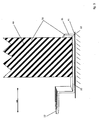
- the connection device 10 is here blocked in its perpendicular to the door leaf plane translational degree of freedom 60, as with respect to the Figures 2 and 3 will be explained.
- connection device 10 By blocking the translational degree of freedom 60, the connection device 10 can not be removed from the fixing element 40, if this, designed as a door, is not opened.
- a first loop 71 which is arranged at one end of a connecting element 70 designed as a cable, is threaded through, and the connecting element 70 is threaded through this first loop 71.
- a very simple mechanical connection between the connecting element 70 and the connecting device 10 is realized, which can easily be released manually when the connecting device 10 is exposed by opening the fixing element 40 provided as a door.
- the liberated connection device 10 is threaded through the first loop 71, so that the first loop 71 can also be pulled out of the loop-like second mold element 12 again.
- the one end of the rope-like connecting element 70 is exposed.
- the connecting element 70 has, at its end opposite the connecting device 10, a second loop 72, in which a closure device 80, here a form of padlock, is suspended and closed.
- the connecting element 70 leads through a receiving lug 33 of the delivery unit 30, this receiving lug 33 being arranged on the container 32 of the delivery unit 30.
- the delivery unit 30 further comprises a cover 31 covering or closing the container 32, on which a pivotable complementary part 34 is arranged.
- the complementary part 34 is pivoted on the receiving lug 33, that the receiving lug 33 and the complementary part 34 together form a box closure.
- the rope-like connecting element 70 passes through the receiving eye 33, so that the complementary part 34 can not be pivoted and thus the lid 31 is fixed on the container 32. Characterized in that in the second loop 72, the connecting element 70, the closure device 80 is mounted, the connecting element 70 can not be pulled out of the receiving lug 33, so that the delivery unit 33 is closed and, in the Fig. 1 illustrated embodiment, when the fixing element 40 is closed inextricably connected to this fixing element 40 and with the connecting device 10 connected thereto.
- connection element 70 can also be pulled out of the receiving lug 33, so that the delivery unit 30 is freely movable and the complementary part 34 of the receptacle 33rd can be swung away and the lid 31 from the container 32 is removable, so that the supplied person can take the contents of the delivery unit 30 in possession.
- connection device 10 configured with a first mold element 11, which can form a positive connection with the door leaf of the fixing element 40.
- This first shaped element is preferably an angle profile, in particular an illustrated U-profile 20, whose leg remote from the second shaped element 12 is designed as a blocking element 21.
- connection device 10 in such a door gap 41 arrange that the U-profile 20 surrounds the fixing element 40 at its edge region, wherein the blocking element 21, the movement of the connection device 10 in a direction of the translational degree of freedom 60, namely in the direction of the second mold element 12th prevents so that the terminal device 10 can be removed only from the fixing member 40 when this fixing member 40 is moved to a position in which the terminal device 10 is removable.
- this position is the position of the door outside the door frame, in which the connection device 10 in a simple manner under the open door pushed or moved away from there.
Landscapes
- Engineering & Computer Science (AREA)
- Food Science & Technology (AREA)
- Supports Or Holders For Household Use (AREA)
Claims (11)
- Dispositif de mise à disposition pour la mise à disposition d'une unité de livraison (30), comprenant un dispositif de raccordement (10) pour la fixation mécanique de l'unité de livraison (30), dans lequel le dispositif de raccordement (10) comporte un premier élément de forme (11) qui peut être raccordé ou est raccordé mécaniquement par forme et/ou par adhérence à un élément de fixation (40) à position fixe ; et le dispositif de raccordement (10) peut être mis en liaison effective ou est en liaison effective avec l'élément de fixation (40) de manière à ce que le dispositif de raccordement (10) et l'élément de fixation (40) forment ensemble une unité de blocage (50) dont l'ouverture nécessite une preuve d'autorisation d'accès,
ainsi que comprenant l'unité de livraison (30) qui peut être raccordée ou est raccordée mécaniquement au dispositif de raccordement (10), dans lequel le dispositif de raccordement (10) comporte un deuxième élément de forme (12) pour la réalisation d'un assemblage par adhérence et/ou par forme avec l'unité de livraison (30) à fixer, dans lequel le deuxième élément de forme (12) est formé comme un oeillet et le dispositif de mise à disposition comporte un élément de raccordement (70) pour la réalisation d'une liaison mécanique entre l'unité de livraison (30) et le dispositif de raccordement (10), dans lequel l'élément de raccordement (70) est une corde avec au moins une boucle (71) disposée à une extrémité, caractérisé
en ce que la boucle (71) est tirée à travers l'oeillet et la corde est tirée à travers cette boucle (71). - Dispositif de mise à disposition selon la revendication 1, caractérisé en ce que le dispositif de raccordement (10) comporte un premier élément de forme (11) qui peut être disposé ou est disposé par assemblage par forme et/ou par adhérence sur un vantail de porte d'une porte de manière à ce que au moins le degré de liberté translationnel (60) perpendiculaire au plan du vantail de porte soit enlevé au dispositif de raccordement (10) lorsque la porte est fermée.
- Dispositif de mise à disposition selon la revendication 2, caractérisé en ce que le premier élément de forme (11) du dispositif de raccordement (10) comporte au moins par zone essentiellement la coupe transversale d'un profilé en U (20), dans lequel une des branches du profilé en U (20) est réalisée comme élément de blocage (21).
- Dispositif de mise à disposition selon la revendication 1, caractérisé en ce que le dispositif de raccordement (10) comporte un premier élément de forme (11) qui peut être disposé ou est disposé par assemblage par forme et/ou par adhérence dans une fente d'une boîte à lettres de manière à ce que au moins le degré de liberté translationnel (60) perpendiculaire au plan dans lequel s'étend la fente de la boîte à lettres soit enlevé au dispositif de raccordement (10) lorsque la boîte à lettres est fermée.
- Dispositif de mise à disposition selon la revendication 1, caractérisé en ce que le dispositif de raccordement (10) est verrouillable et déverrouillable et comporte un premier élément de forme (11) qui peut être raccordé ou est raccordé par assemblage par forme et/ou par adhérence à un élément d'une porte de jardin ou d'une clôture de jardin de manière à ce que le dispositif de raccordement (10) soit fixé à la porte de jardin ou la clôture de jardin à l'état verrouillé.
- Dispositif de mise à disposition selon l'une quelconque des revendications précédentes, caractérisé en ce que l'élément de connexion (70) est une corde avec des boucles (71, 72) disposées aux deux extrémités, dans lequel la deuxième boucle (72) d'un élément de forme de l'unité de livraison est protégée au moyen d'un dispositif de fermeture (80) par assemblage par adhérence et/ou par forme contre l'enlèvement.
- Dispositif de mise à disposition selon la revendication 6, caractérisé en ce que le dispositif de fermeture (80) est un cadenas, dans lequel la deuxième boucle (72) de la corde est tirée à travers un oeillet de réception (33) de l'unité de livraison (30) et le cadenas est dans accroché la deuxième boucle (72) et fermé, dans lequel la largeur intérieure maximal de l'oeillet de réception (33) de l'unité de livraison (30) est inférieure à l'extension spatiale minimale du cadenas.
- Dispositif de mise à disposition selon la revendication 7, caractérisé en ce que l'unité de livraison (30) comporte un couvercle (31) et un récipient (32), dans lequel l'oeillet de réception (33) est disposé sur un des éléments couvercle (31) et récipient (32) et une pièce complémentaire (34) est disposée sur l'autre élément respectif pouvant être essentiellement fixé dans sa position lorsqu'un objet, comme par exemple la corde, s'étend à travers l'oeillet de réception (33).
- Système de mise à disposition, comprenant un dispositif de mise à disposition selon l'une quelconque des revendications 1 à 8, ainsi qu'un élément de fixation (40) mis en liaison effective avec le dispositif de raccordement (10) du dispositif de mise à disposition de manière à ce que le dispositif de raccordement (10) et l'élément de fixation (40) forment ensemble une unité de blocage (50) dont l'ouverture nécessite une preuve d'autorisation d'accès.
- Procédé de mise à disposition d'une unité de livraison, dans lequel un système de mise à disposition selon la revendication 9 est utilisé pour raccorder mécaniquement une unité de livraison (30) au moyen du dispositif de raccordement (10) à l'élément de fixation (40), dans lequel une liaison mécanique est établie entre le dispositif de raccordement (10) et l'unité de livraison (30).
- Procédé de mise à disposition d'une unité de livraison (30) selon la revendication 10, caractérisé en ce que le dispositif de mise à disposition (10) comporte un oeillet comme deuxième élément de forme (12) et le dispositif de mise à disposition comprend en outre entre le dispositif de raccordement (10) et l'unité de livraison (30) un élément de raccordement (70) qui est une corde avec des boucles (71, 72) disposées aux deux extrémités ; et en ce que l'unité de livraison (30) comporte un couvercle (31) et un récipient (32), dans lequel un oeillet de réception (33) est disposé sur un des éléments couvercle (31) et récipient (32) et une pièce complémentaire (34) est disposée sur l'autre élément respectif pouvant être essentiellement fixé dans sa position lorsqu'un objet s'étend à travers l'oeillet de réception (33),
dans lequel une première boucle (71) de la corde est insérée à travers l'oeillet du dispositif de raccordement (10) et l'élément de raccordement (70) après cela enfilé à travers la première boucle (71) et la deuxième boucle (72) de la corde est tirée à travers l'oeillet de réception (33) de l'unité de livraison (30) et après cela un cadenas est accroché dans la deuxième boucle (72) et verrouillé.
Priority Applications (1)
| Application Number | Priority Date | Filing Date | Title |
|---|---|---|---|
| PL14075022T PL2801302T3 (pl) | 2013-05-08 | 2014-04-14 | Urządzenie udostępniające, system udostępniania i sposób udostępniania jednostki dostawczej |
Applications Claiming Priority (1)
| Application Number | Priority Date | Filing Date | Title |
|---|---|---|---|
| DE201310104755 DE102013104755B4 (de) | 2013-05-08 | 2013-05-08 | Bereitstellungseinrichtung, Bereitstellungssystem und Verfahren zur Bereitstellung einer Liefereinheit |
Publications (2)
| Publication Number | Publication Date |
|---|---|
| EP2801302A1 EP2801302A1 (fr) | 2014-11-12 |
| EP2801302B1 true EP2801302B1 (fr) | 2016-10-19 |
Family
ID=50543421
Family Applications (1)
| Application Number | Title | Priority Date | Filing Date |
|---|---|---|---|
| EP14075022.5A Not-in-force EP2801302B1 (fr) | 2013-05-08 | 2014-04-14 | Dispositif de disposition, système de disposition et procédé pour la disposition d'un unité de livraison |
Country Status (6)
| Country | Link |
|---|---|
| EP (1) | EP2801302B1 (fr) |
| DE (1) | DE102013104755B4 (fr) |
| DK (1) | DK2801302T3 (fr) |
| ES (1) | ES2619607T3 (fr) |
| PL (1) | PL2801302T3 (fr) |
| PT (1) | PT2801302T (fr) |
Cited By (1)
| Publication number | Priority date | Publication date | Assignee | Title |
|---|---|---|---|---|
| US10583853B2 (en) | 2018-02-22 | 2020-03-10 | John Brilhante | Delivered package securment system |
Families Citing this family (5)
| Publication number | Priority date | Publication date | Assignee | Title |
|---|---|---|---|---|
| DE102014110688B4 (de) * | 2014-07-29 | 2017-04-20 | Reiner Probst | Vorrichtung zur Aufnahme von Paketen oder anderen Lieferungen |
| LT6451B (lt) | 2016-01-18 | 2017-09-11 | Uab "Zzz.Lt" | Siuntinių dėžės saugus užrakinimo įtaisas ir būdas |
| DE102017208050A1 (de) | 2017-05-12 | 2018-11-15 | Ford Global Technologies, Llc | System und Verfahren zum Ausliefern und/oder Abholen von Paketen |
| US10383471B1 (en) | 2018-07-31 | 2019-08-20 | Pristtine, Inc. | Package protecting delivery receptacle with expandable attachment bracket |
| US10932602B2 (en) * | 2018-09-20 | 2021-03-02 | Jerry L. Hauck | Theft prevention package containers |
Family Cites Families (4)
| Publication number | Priority date | Publication date | Assignee | Title |
|---|---|---|---|---|
| ES2140308B1 (es) * | 1997-07-07 | 2000-10-16 | Butano Ormad S L | Dispositivo-monedero con pletina de sustentacion y sirga para sujecion de botellas de butano. |
| GB2340479A (en) * | 1998-08-11 | 2000-02-23 | Butler Boxes Limited | Container lockable to an anchorage point |
| GB2424919B (en) * | 2005-03-24 | 2009-09-23 | Peter Bruce Kerr | A device for securing a container in a particular place |
| US9926108B2 (en) * | 2011-09-28 | 2018-03-27 | Gloria Selena Wiley | Secure unattended delivery apparatus |
-
2013
- 2013-05-08 DE DE201310104755 patent/DE102013104755B4/de not_active Expired - Fee Related
-
2014
- 2014-04-14 ES ES14075022.5T patent/ES2619607T3/es active Active
- 2014-04-14 PL PL14075022T patent/PL2801302T3/pl unknown
- 2014-04-14 DK DK14075022.5T patent/DK2801302T3/en active
- 2014-04-14 PT PT140750225T patent/PT2801302T/pt unknown
- 2014-04-14 EP EP14075022.5A patent/EP2801302B1/fr not_active Not-in-force
Cited By (1)
| Publication number | Priority date | Publication date | Assignee | Title |
|---|---|---|---|---|
| US10583853B2 (en) | 2018-02-22 | 2020-03-10 | John Brilhante | Delivered package securment system |
Also Published As
| Publication number | Publication date |
|---|---|
| DE102013104755B4 (de) | 2015-05-13 |
| PL2801302T3 (pl) | 2017-07-31 |
| EP2801302A1 (fr) | 2014-11-12 |
| ES2619607T3 (es) | 2017-06-26 |
| DK2801302T3 (en) | 2017-01-30 |
| DE102013104755A1 (de) | 2014-11-13 |
| PT2801302T (pt) | 2017-01-31 |
Similar Documents
| Publication | Publication Date | Title |
|---|---|---|
| EP2801302B1 (fr) | Dispositif de disposition, système de disposition et procédé pour la disposition d'un unité de livraison | |
| DE2920990C2 (de) | Schiebefenster mit mindestens einem horizontal verschiebbaren Schiebeflügel, dem eine Sicherheitseinrichtung gegen seine Entnahme zugeordnet ist | |
| EP2746496A2 (fr) | Dispositif de sécurité pour une poignée de fenêtre ou de porte | |
| EP3075288A1 (fr) | Dispositif de verrouillage du compartiment à paquets d'une boîte à lettres et utilisation du dispositif | |
| DE202015104085U1 (de) | An einen Fahrrad-Gepäckträger anschließbares Gepäckstück | |
| EP1705332A1 (fr) | Casier verrouillable | |
| DE102010003641A1 (de) | Befestigungsvorrichtung für einen Motorradhelm | |
| DE102017002954A1 (de) | Postempfangsbox für die Aufnahme von Postsendungen an Wohnungstüren | |
| DE19629619C2 (de) | Bewegliche Schutzwand | |
| DE102017003453B4 (de) | Sperrvorrichtung für einen Betätiger einer Sicherheitszuhaltung | |
| EP0887250A2 (fr) | Support pour récipients en général et en particulier pour serviettes, utilisable pour motorcyclettes ou similaires | |
| DE102010015476A1 (de) | Verriegelungsvorrichtung für ein Ladestellentor | |
| DE102015002277B4 (de) | Briefkasten für einen Gitterstabzaun | |
| DE102017009642A1 (de) | Verriegelung | |
| EP0535503A1 (fr) | Dispositif de fixation pour deux portes | |
| DE7247564U (de) | Vorrichtung zur Sicherung von Automaten u dgl, wie insbesondere Geld Spielautomaten, gegen Aufbrechen | |
| DE102010003155B4 (de) | Briefkasten oder Briefkastenanlage mit einer Einwurfsperre zum Verschließen der Einwurföffnung | |
| DE202007014456U1 (de) | Einwurfsperre für Briefkästen u.dgl. | |
| DE2913112A1 (de) | Sicherung fuer ein abdeckgitter eines kellerfensterschachts | |
| DE202006012866U1 (de) | Verschließbarer Sicherheitsbehälter | |
| DE202007004472U1 (de) | Wertbehältnis und Vorrichtung zum Einbringen von Gegenständen in Wertbehältnisse | |
| DE202013105346U1 (de) | Grabmal | |
| DE29513923U1 (de) | Vorrichtung zur Sicherung von Fenstern, Türen u.dgl. | |
| DE29823638U1 (de) | Diebstahlsicherung für Abrollcontainer | |
| DE8715741U1 (de) | Sicherheitseinrichtung an Münzsammlern |
Legal Events
| Date | Code | Title | Description |
|---|---|---|---|
| PUAI | Public reference made under article 153(3) epc to a published international application that has entered the european phase |
Free format text: ORIGINAL CODE: 0009012 |
|
| 17P | Request for examination filed |
Effective date: 20140414 |
|
| AK | Designated contracting states |
Kind code of ref document: A1 Designated state(s): AL AT BE BG CH CY CZ DE DK EE ES FI FR GB GR HR HU IE IS IT LI LT LU LV MC MK MT NL NO PL PT RO RS SE SI SK SM TR |
|
| AX | Request for extension of the european patent |
Extension state: BA ME |
|
| R17P | Request for examination filed (corrected) |
Effective date: 20150121 |
|
| RBV | Designated contracting states (corrected) |
Designated state(s): AL AT BE BG CH CY CZ DE DK EE ES FI FR GB GR HR HU IE IS IT LI LT LU LV MC MK MT NL NO PL PT RO RS SE SI SK SM TR |
|
| GRAP | Despatch of communication of intention to grant a patent |
Free format text: ORIGINAL CODE: EPIDOSNIGR1 |
|
| RIC1 | Information provided on ipc code assigned before grant |
Ipc: A47G 29/20 20060101AFI20160406BHEP |
|
| RIN1 | Information on inventor provided before grant (corrected) |
Inventor name: KRAKER VON SCHWARZENFELD, THOMAS |
|
| INTG | Intention to grant announced |
Effective date: 20160506 |
|
| GRAS | Grant fee paid |
Free format text: ORIGINAL CODE: EPIDOSNIGR3 |
|
| GRAA | (expected) grant |
Free format text: ORIGINAL CODE: 0009210 |
|
| AK | Designated contracting states |
Kind code of ref document: B1 Designated state(s): AL AT BE BG CH CY CZ DE DK EE ES FI FR GB GR HR HU IE IS IT LI LT LU LV MC MK MT NL NO PL PT RO RS SE SI SK SM TR |
|
| REG | Reference to a national code |
Ref country code: GB Ref legal event code: FG4D Free format text: NOT ENGLISH |
|
| REG | Reference to a national code |
Ref country code: CH Ref legal event code: EP |
|
| REG | Reference to a national code |
Ref country code: AT Ref legal event code: REF Ref document number: 837584 Country of ref document: AT Kind code of ref document: T Effective date: 20161115 |
|
| REG | Reference to a national code |
Ref country code: IE Ref legal event code: FG4D Free format text: LANGUAGE OF EP DOCUMENT: GERMAN |
|
| REG | Reference to a national code |
Ref country code: DE Ref legal event code: R096 Ref document number: 502014001723 Country of ref document: DE |
|
| REG | Reference to a national code |
Ref country code: NO Ref legal event code: T2 Effective date: 20161019 |
|
| REG | Reference to a national code |
Ref country code: DK Ref legal event code: T3 Effective date: 20170127 |
|
| REG | Reference to a national code |
Ref country code: PT Ref legal event code: SC4A Ref document number: 2801302 Country of ref document: PT Date of ref document: 20170131 Kind code of ref document: T Free format text: AVAILABILITY OF NATIONAL TRANSLATION Effective date: 20170118 |
|
| REG | Reference to a national code |
Ref country code: NL Ref legal event code: FP |
|
| REG | Reference to a national code |
Ref country code: SE Ref legal event code: TRGR |
|
| REG | Reference to a national code |
Ref country code: LT Ref legal event code: MG4D |
|
| PG25 | Lapsed in a contracting state [announced via postgrant information from national office to epo] |
Ref country code: LV Free format text: LAPSE BECAUSE OF FAILURE TO SUBMIT A TRANSLATION OF THE DESCRIPTION OR TO PAY THE FEE WITHIN THE PRESCRIBED TIME-LIMIT Effective date: 20161019 |
|
| REG | Reference to a national code |
Ref country code: FR Ref legal event code: PLFP Year of fee payment: 4 |
|
| PG25 | Lapsed in a contracting state [announced via postgrant information from national office to epo] |
Ref country code: GR Free format text: LAPSE BECAUSE OF FAILURE TO SUBMIT A TRANSLATION OF THE DESCRIPTION OR TO PAY THE FEE WITHIN THE PRESCRIBED TIME-LIMIT Effective date: 20170120 Ref country code: LT Free format text: LAPSE BECAUSE OF FAILURE TO SUBMIT A TRANSLATION OF THE DESCRIPTION OR TO PAY THE FEE WITHIN THE PRESCRIBED TIME-LIMIT Effective date: 20161019 |
|
| PG25 | Lapsed in a contracting state [announced via postgrant information from national office to epo] |
Ref country code: RS Free format text: LAPSE BECAUSE OF FAILURE TO SUBMIT A TRANSLATION OF THE DESCRIPTION OR TO PAY THE FEE WITHIN THE PRESCRIBED TIME-LIMIT Effective date: 20161019 Ref country code: HR Free format text: LAPSE BECAUSE OF FAILURE TO SUBMIT A TRANSLATION OF THE DESCRIPTION OR TO PAY THE FEE WITHIN THE PRESCRIBED TIME-LIMIT Effective date: 20161019 Ref country code: IS Free format text: LAPSE BECAUSE OF FAILURE TO SUBMIT A TRANSLATION OF THE DESCRIPTION OR TO PAY THE FEE WITHIN THE PRESCRIBED TIME-LIMIT Effective date: 20170219 Ref country code: FI Free format text: LAPSE BECAUSE OF FAILURE TO SUBMIT A TRANSLATION OF THE DESCRIPTION OR TO PAY THE FEE WITHIN THE PRESCRIBED TIME-LIMIT Effective date: 20161019 |
|
| REG | Reference to a national code |
Ref country code: ES Ref legal event code: FG2A Ref document number: 2619607 Country of ref document: ES Kind code of ref document: T3 Effective date: 20170626 |
|
| REG | Reference to a national code |
Ref country code: DE Ref legal event code: R097 Ref document number: 502014001723 Country of ref document: DE |
|
| PG25 | Lapsed in a contracting state [announced via postgrant information from national office to epo] |
Ref country code: RO Free format text: LAPSE BECAUSE OF FAILURE TO SUBMIT A TRANSLATION OF THE DESCRIPTION OR TO PAY THE FEE WITHIN THE PRESCRIBED TIME-LIMIT Effective date: 20161019 Ref country code: SK Free format text: LAPSE BECAUSE OF FAILURE TO SUBMIT A TRANSLATION OF THE DESCRIPTION OR TO PAY THE FEE WITHIN THE PRESCRIBED TIME-LIMIT Effective date: 20161019 Ref country code: EE Free format text: LAPSE BECAUSE OF FAILURE TO SUBMIT A TRANSLATION OF THE DESCRIPTION OR TO PAY THE FEE WITHIN THE PRESCRIBED TIME-LIMIT Effective date: 20161019 |
|
| PLBE | No opposition filed within time limit |
Free format text: ORIGINAL CODE: 0009261 |
|
| STAA | Information on the status of an ep patent application or granted ep patent |
Free format text: STATUS: NO OPPOSITION FILED WITHIN TIME LIMIT |
|
| PG25 | Lapsed in a contracting state [announced via postgrant information from national office to epo] |
Ref country code: SM Free format text: LAPSE BECAUSE OF FAILURE TO SUBMIT A TRANSLATION OF THE DESCRIPTION OR TO PAY THE FEE WITHIN THE PRESCRIBED TIME-LIMIT Effective date: 20161019 Ref country code: BG Free format text: LAPSE BECAUSE OF FAILURE TO SUBMIT A TRANSLATION OF THE DESCRIPTION OR TO PAY THE FEE WITHIN THE PRESCRIBED TIME-LIMIT Effective date: 20170119 |
|
| 26N | No opposition filed |
Effective date: 20170720 |
|
| PG25 | Lapsed in a contracting state [announced via postgrant information from national office to epo] |
Ref country code: SI Free format text: LAPSE BECAUSE OF FAILURE TO SUBMIT A TRANSLATION OF THE DESCRIPTION OR TO PAY THE FEE WITHIN THE PRESCRIBED TIME-LIMIT Effective date: 20161019 |
|
| REG | Reference to a national code |
Ref country code: IE Ref legal event code: MM4A |
|
| PG25 | Lapsed in a contracting state [announced via postgrant information from national office to epo] |
Ref country code: MC Free format text: LAPSE BECAUSE OF FAILURE TO SUBMIT A TRANSLATION OF THE DESCRIPTION OR TO PAY THE FEE WITHIN THE PRESCRIBED TIME-LIMIT Effective date: 20161019 |
|
| REG | Reference to a national code |
Ref country code: FR Ref legal event code: PLFP Year of fee payment: 5 |
|
| PG25 | Lapsed in a contracting state [announced via postgrant information from national office to epo] |
Ref country code: IE Free format text: LAPSE BECAUSE OF NON-PAYMENT OF DUE FEES Effective date: 20170414 |
|
| PGFP | Annual fee paid to national office [announced via postgrant information from national office to epo] |
Ref country code: LU Payment date: 20180423 Year of fee payment: 5 Ref country code: NL Payment date: 20180423 Year of fee payment: 5 |
|
| PGFP | Annual fee paid to national office [announced via postgrant information from national office to epo] |
Ref country code: DK Payment date: 20180424 Year of fee payment: 5 Ref country code: ES Payment date: 20180523 Year of fee payment: 5 Ref country code: CH Payment date: 20180424 Year of fee payment: 5 Ref country code: DE Payment date: 20180423 Year of fee payment: 5 |
|
| PGFP | Annual fee paid to national office [announced via postgrant information from national office to epo] |
Ref country code: BE Payment date: 20180423 Year of fee payment: 5 Ref country code: FR Payment date: 20180424 Year of fee payment: 5 Ref country code: IT Payment date: 20180420 Year of fee payment: 5 |
|
| PG25 | Lapsed in a contracting state [announced via postgrant information from national office to epo] |
Ref country code: MT Free format text: LAPSE BECAUSE OF FAILURE TO SUBMIT A TRANSLATION OF THE DESCRIPTION OR TO PAY THE FEE WITHIN THE PRESCRIBED TIME-LIMIT Effective date: 20161019 |
|
| PGFP | Annual fee paid to national office [announced via postgrant information from national office to epo] |
Ref country code: SE Payment date: 20180424 Year of fee payment: 5 |
|
| PGFP | Annual fee paid to national office [announced via postgrant information from national office to epo] |
Ref country code: GB Payment date: 20180424 Year of fee payment: 5 |
|
| PG25 | Lapsed in a contracting state [announced via postgrant information from national office to epo] |
Ref country code: HU Free format text: LAPSE BECAUSE OF FAILURE TO SUBMIT A TRANSLATION OF THE DESCRIPTION OR TO PAY THE FEE WITHIN THE PRESCRIBED TIME-LIMIT; INVALID AB INITIO Effective date: 20140414 |
|
| PGFP | Annual fee paid to national office [announced via postgrant information from national office to epo] |
Ref country code: PT Payment date: 20190405 Year of fee payment: 6 Ref country code: PL Payment date: 20190404 Year of fee payment: 6 Ref country code: NO Payment date: 20190423 Year of fee payment: 6 Ref country code: CZ Payment date: 20190403 Year of fee payment: 6 |
|
| PG25 | Lapsed in a contracting state [announced via postgrant information from national office to epo] |
Ref country code: CY Free format text: LAPSE BECAUSE OF FAILURE TO SUBMIT A TRANSLATION OF THE DESCRIPTION OR TO PAY THE FEE WITHIN THE PRESCRIBED TIME-LIMIT Effective date: 20161019 |
|
| PGFP | Annual fee paid to national office [announced via postgrant information from national office to epo] |
Ref country code: AT Payment date: 20190416 Year of fee payment: 6 |
|
| REG | Reference to a national code |
Ref country code: DE Ref legal event code: R119 Ref document number: 502014001723 Country of ref document: DE |
|
| PG25 | Lapsed in a contracting state [announced via postgrant information from national office to epo] |
Ref country code: MK Free format text: LAPSE BECAUSE OF FAILURE TO SUBMIT A TRANSLATION OF THE DESCRIPTION OR TO PAY THE FEE WITHIN THE PRESCRIBED TIME-LIMIT Effective date: 20161019 |
|
| REG | Reference to a national code |
Ref country code: CH Ref legal event code: PL |
|
| REG | Reference to a national code |
Ref country code: DK Ref legal event code: EBP Effective date: 20190430 |
|
| REG | Reference to a national code |
Ref country code: SE Ref legal event code: EUG |
|
| REG | Reference to a national code |
Ref country code: NL Ref legal event code: MM Effective date: 20190501 |
|
| REG | Reference to a national code |
Ref country code: BE Ref legal event code: MM Effective date: 20190430 |
|
| GBPC | Gb: european patent ceased through non-payment of renewal fee |
Effective date: 20190414 |
|
| PG25 | Lapsed in a contracting state [announced via postgrant information from national office to epo] |
Ref country code: LU Free format text: LAPSE BECAUSE OF NON-PAYMENT OF DUE FEES Effective date: 20190414 |
|
| PG25 | Lapsed in a contracting state [announced via postgrant information from national office to epo] |
Ref country code: DE Free format text: LAPSE BECAUSE OF NON-PAYMENT OF DUE FEES Effective date: 20191101 Ref country code: CH Free format text: LAPSE BECAUSE OF NON-PAYMENT OF DUE FEES Effective date: 20190430 Ref country code: NL Free format text: LAPSE BECAUSE OF NON-PAYMENT OF DUE FEES Effective date: 20190501 Ref country code: SE Free format text: LAPSE BECAUSE OF NON-PAYMENT OF DUE FEES Effective date: 20190415 Ref country code: GB Free format text: LAPSE BECAUSE OF NON-PAYMENT OF DUE FEES Effective date: 20190414 Ref country code: LI Free format text: LAPSE BECAUSE OF NON-PAYMENT OF DUE FEES Effective date: 20190430 |
|
| PG25 | Lapsed in a contracting state [announced via postgrant information from national office to epo] |
Ref country code: FR Free format text: LAPSE BECAUSE OF NON-PAYMENT OF DUE FEES Effective date: 20190430 Ref country code: BE Free format text: LAPSE BECAUSE OF NON-PAYMENT OF DUE FEES Effective date: 20190430 |
|
| PG25 | Lapsed in a contracting state [announced via postgrant information from national office to epo] |
Ref country code: TR Free format text: LAPSE BECAUSE OF FAILURE TO SUBMIT A TRANSLATION OF THE DESCRIPTION OR TO PAY THE FEE WITHIN THE PRESCRIBED TIME-LIMIT Effective date: 20161019 |
|
| PG25 | Lapsed in a contracting state [announced via postgrant information from national office to epo] |
Ref country code: IT Free format text: LAPSE BECAUSE OF NON-PAYMENT OF DUE FEES Effective date: 20190414 Ref country code: DK Free format text: LAPSE BECAUSE OF NON-PAYMENT OF DUE FEES Effective date: 20190430 |
|
| PG25 | Lapsed in a contracting state [announced via postgrant information from national office to epo] |
Ref country code: AL Free format text: LAPSE BECAUSE OF FAILURE TO SUBMIT A TRANSLATION OF THE DESCRIPTION OR TO PAY THE FEE WITHIN THE PRESCRIBED TIME-LIMIT Effective date: 20161019 |
|
| REG | Reference to a national code |
Ref country code: ES Ref legal event code: FD2A Effective date: 20200828 |
|
| PG25 | Lapsed in a contracting state [announced via postgrant information from national office to epo] |
Ref country code: ES Free format text: LAPSE BECAUSE OF NON-PAYMENT OF DUE FEES Effective date: 20190415 |
|
| REG | Reference to a national code |
Ref country code: NO Ref legal event code: MMEP |
|
| REG | Reference to a national code |
Ref country code: AT Ref legal event code: MM01 Ref document number: 837584 Country of ref document: AT Kind code of ref document: T Effective date: 20200414 |
|
| PG25 | Lapsed in a contracting state [announced via postgrant information from national office to epo] |
Ref country code: PT Free format text: LAPSE BECAUSE OF NON-PAYMENT OF DUE FEES Effective date: 20201014 Ref country code: AT Free format text: LAPSE BECAUSE OF NON-PAYMENT OF DUE FEES Effective date: 20200414 Ref country code: NO Free format text: LAPSE BECAUSE OF NON-PAYMENT OF DUE FEES Effective date: 20200430 Ref country code: CZ Free format text: LAPSE BECAUSE OF NON-PAYMENT OF DUE FEES Effective date: 20200414 |
|
| PG25 | Lapsed in a contracting state [announced via postgrant information from national office to epo] |
Ref country code: PL Free format text: LAPSE BECAUSE OF NON-PAYMENT OF DUE FEES Effective date: 20200414 |