EP2801427B1 - Schwingungsdämpfende Unterlage und Fräsverfahren eines Metallteils - Google Patents
Schwingungsdämpfende Unterlage und Fräsverfahren eines Metallteils Download PDFInfo
- Publication number
- EP2801427B1 EP2801427B1 EP14161163.2A EP14161163A EP2801427B1 EP 2801427 B1 EP2801427 B1 EP 2801427B1 EP 14161163 A EP14161163 A EP 14161163A EP 2801427 B1 EP2801427 B1 EP 2801427B1
- Authority
- EP
- European Patent Office
- Prior art keywords
- metal part
- milling
- elastomer pad
- elastic elements
- support
- Prior art date
- Legal status (The legal status is an assumption and is not a legal conclusion. Google has not performed a legal analysis and makes no representation as to the accuracy of the status listed.)
- Active
Links
Images


Classifications
-
- B—PERFORMING OPERATIONS; TRANSPORTING
- B23—MACHINE TOOLS; METAL-WORKING NOT OTHERWISE PROVIDED FOR
- B23C—MILLING
- B23C9/00—Details or accessories so far as specially adapted to milling machines or cutter
-
- B—PERFORMING OPERATIONS; TRANSPORTING
- B23—MACHINE TOOLS; METAL-WORKING NOT OTHERWISE PROVIDED FOR
- B23C—MILLING
- B23C3/00—Milling particular work; Special milling operations; Machines therefor
-
- B—PERFORMING OPERATIONS; TRANSPORTING
- B23—MACHINE TOOLS; METAL-WORKING NOT OTHERWISE PROVIDED FOR
- B23C—MILLING
- B23C3/00—Milling particular work; Special milling operations; Machines therefor
- B23C3/13—Surface milling of plates, sheets or strips
-
- B—PERFORMING OPERATIONS; TRANSPORTING
- B23—MACHINE TOOLS; METAL-WORKING NOT OTHERWISE PROVIDED FOR
- B23Q—DETAILS, COMPONENTS, OR ACCESSORIES FOR MACHINE TOOLS, e.g. ARRANGEMENTS FOR COPYING OR CONTROLLING; MACHINE TOOLS IN GENERAL CHARACTERISED BY THE CONSTRUCTION OF PARTICULAR DETAILS OR COMPONENTS; COMBINATIONS OR ASSOCIATIONS OF METAL-WORKING MACHINES, NOT DIRECTED TO A PARTICULAR RESULT
- B23Q11/00—Accessories fitted to machine tools for keeping tools or parts of the machine in good working condition or for cooling work; Safety devices specially combined with or arranged in, or specially adapted for use in connection with, machine tools
- B23Q11/0032—Arrangements for preventing or isolating vibrations in parts of the machine
-
- B—PERFORMING OPERATIONS; TRANSPORTING
- B23—MACHINE TOOLS; METAL-WORKING NOT OTHERWISE PROVIDED FOR
- B23Q—DETAILS, COMPONENTS, OR ACCESSORIES FOR MACHINE TOOLS, e.g. ARRANGEMENTS FOR COPYING OR CONTROLLING; MACHINE TOOLS IN GENERAL CHARACTERISED BY THE CONSTRUCTION OF PARTICULAR DETAILS OR COMPONENTS; COMBINATIONS OR ASSOCIATIONS OF METAL-WORKING MACHINES, NOT DIRECTED TO A PARTICULAR RESULT
- B23Q3/00—Devices holding, supporting, or positioning work or tools, of a kind normally removable from the machine
- B23Q3/02—Devices holding, supporting, or positioning work or tools, of a kind normally removable from the machine for mounting on a work-table, tool-slide, or analogous part
- B23Q3/06—Work-clamping means
-
- B—PERFORMING OPERATIONS; TRANSPORTING
- B23—MACHINE TOOLS; METAL-WORKING NOT OTHERWISE PROVIDED FOR
- B23C—MILLING
- B23C2250/00—Compensating adverse effects during milling
- B23C2250/16—Damping vibrations
Definitions
- the present invention relates to the field of mechanical milling, more particularly the milling of a metal part in order to obtain a predetermined surface state.
- the invention relates to a milling method in the context of obtaining a piece of lighting device for a motor vehicle.
- the lighting device comprises in particular two lighting modes: long range ("full lights”) and crossing ("high beam”).
- the beam obtained is directed straight towards the front of the vehicle, for a maximum range, generally of the order of 150 meters.
- the resulting beam is directed downwards, the range is reduced to about 80 meters, but drivers of other forward-facing vehicles are less likely to be dazzled.
- the figure 1 shows an embodiment of such a lighting device 100.
- the lighting device 100 comprises two light sources 101a, 101b, for example light-emitting diodes.
- Said light sources 101a, 101b are located in respective convex mirrors 103a, 103b, of optical axis directed towards the front of the vehicle, forming the long-range and crossing beams respectively from the light of one of the light sources 101a. , 101b.
- the convex mirrors 103a, 103b focus the light emitted by the light sources 101a, 101b, and direct it forward.
- Said mirrors 103a, 103b are open on one side, and are located on the other side of a separator 105, shown here in section.
- the separator 105 is of very flattened triangular section, with a ridge A located towards the front.
- a lens 107 which shapes the emitted light beams.
- edge A which must be maintained in the state prevents the recourse to conventional aggression or chemical or electrochemical application processes for obtaining reflective surfaces, said processes deteriorating the edge A.
- the application of acids for etching or electrolytic deposition of metal deforms the edge A.
- the elastic elements are intended to be deformed during the clamping of the metal part.
- the metal part can be wedged by compression of the elastic elements, which absorb the deformations, and the elastomeric pad absorbs micro-vibrations.
- the device may further include one or more of the following features.
- the elastomer buffer has a hardness between 70 and 90 Shore
- the elastic members comprise a spring blade or helical springs.
- the invention also relates to the support of a metal part to be milled, comprising a device as previously described.
- the support the elastic elements are mounted on a rotary shaft and forming a rotatable arm supporting the elastomeric pad and configured to contact said elastomeric pad with the metal piece when the latter is positioned in the means of clamping.
- the rotary shaft is actuated by a rotary jack configured to apply a force to drive the elastomeric pad from 0.5mm to 3mm against the metal piece during milling of the metal piece.
- the rotary axis is oriented vertically.
- the clamping means of the metal part can then be arranged relative to the anti-vibration device so that the metal part depresses in the flanged state the elastomeric pad from 0.5mm to 3mm.
- Said method may further comprise an additional step of pre-milling, performed before the step in which the milling tool is passed over the surface, an additional step in which a preliminary milling of the surface is performed, so as to leave an extra thickness from 1 to 5 microns.
- said elastomer pad is advantageously depressed by about 0.5 to 3 mm.
- the metal part is advantageously arranged so that the edge forms an overhang of 0.05 and 0.2 millimeters.
- FIG 2 is shown schematically an embodiment of separator 105 as used in figure 1 .
- the directions such as “frontal”, “lateral”, “forward / backward” are taken in relation to the orientation of the separator 105 in figure 1 , the front corresponding to the main direction of the light beam (see figure 1 ).
- Said separator 105 comprises two reflecting surfaces 1a, 1b on each side and inclined in the longitudinal direction, separated by a separating chamfer 3, a few tenths of a millimeter and inclined at about 45 °.
- the separating chamfer 3 makes it possible to orient the surfaces 1a, 1b and 1c, 1d differently in order to shape the light beam of the lighting device.
- the separating chamfer 3 makes it possible to obtain a lighting device beam 100 with a portion of cone raised relative to the rest, illuminating further at the side of the road.
- the separator 105 is made of aluminum alloys, in particular alloys of soft aluminum, for example the aluminum series 6000 and 7000, preferably relatively poor in additional elements, for example the aluminum alloy 6060.
- the separator 105 comprises holes 5, which allow the maintenance of said separator 105 during its machining. It also comprises here a keying hollow 7 in the form of a recess on one of its sides for the orientation of the piece.
- the separator 105 is obtained by milling a blank obtained for example by cutting.
- An example of milling method 200 is illustrated in figure 3 , in the form of a simplified flowchart.
- the first step 201 is here a prefraising, performed according to known methods, so as to leave only one extra thickness between 1 and 5 micrometers (high precision milling) at least at the surfaces 1a, 1b, 1c, 1d, intended to become reflective.
- the prefilled blank is arranged and clamped on a support 300, one embodiment of which is shown in FIG. Figures 4 and 5 .
- the support 300 comprises two tables 301, preferably made to be heavy, and fixed on a support 303, here by inserting wheelbases (not visible) at the legs of the tables 301 in rails 305 of the support 303.
- the tables 301 have at least one, here each two (four in all), locations 307 of work.
- locations 307 are arranged and clamped separators 105 for their machining.
- the locations 307 comprise for this purpose fingers (not visible) which are inserted into the bores 5 and the polarizers 7 of said separators 105.
- the tables 301 have in particular respectively a plate inclined at an angle corresponding to the angle given to the surface 1a, 1b, 1c, 1d machined, so that the movements of the milling tool are horizontal.
- Tables 301 of the figure 4 each show a particular embodiment.
- the separator 105 is initially arranged on a movable jaw 309 (which includes the fingers that fit into the bores 5 and keyed 7), said movable jaw 309 then supporting said separator 105 against a fixed jaw 311 for clamping the separator 105.
- the separator 105 is initially disposed on the fixed jaw 311, and the movable jaw 309 then covers and press the separator 105.
- the separator 105 is placed in the locations 307 on an anti-vibration device 313, shown in more detail in FIG. figure 5 .
- an anti-vibration device 313 on which a separator 105 is based.
- the anti-vibration device 313 comprises an elastomer pad 315, disposed on a metal plate 317, and an elastic element 319, here in the form of a blade. spring.
- the spring blade 319 is here made of metal, for example steel, and has a bore 321 for fixing it to the location 307, in particular by means of a screw, and is produced in the form of a finer extension of the plate. 317, and in particular material with said plate 317.
- the plate 317 here further comprises a bore 323 for fixing the elastomer pad 315 by means of a screw which, advantageously, does not pass through the pad 315. In this way the elastomer pads 315 can be replaced more easily.
- the elastomer buffer 315 has a hardness of 60 to 90 Shore, and may in particular be made of rubber, potentially crosslinked.
- the separator 105 is in particular disposed on the elastomer pad 315 so that the thin edge A protrudes from the front surface of the pad forming an overhang of between 0.05 and 0.2 mm, preferably around 0.1 mm. Indeed, a longer length causes a risk of oscillations of the overhanging portion, which causes an increase in roughness. A shorter length causes a risk of attack of the elastomeric pad 315 by the tool 9, damaging said buffer 315 while potentially polluting the tool 9 with elastomer residues.
- the leaf spring 319 is deformed when attaching the separator 105, plus Especially under the effect of compression by the movable jaw 309.
- the elastomeric buffer 315 absorbs micro-vibrations resulting from milling, while excessive compression of the stamp against the workpiece 105 to mark the surface thereof. This combined use of elastic elements 319 and elastomer buffer 315 makes it possible to reduce the vibrations sufficiently to obtain a high reflectivity surface state.
- Other embodiments may include other forms of resilient members 319: e.g., coil springs, or a combination of coil springs and leaf springs.
- the leaf springs 319 have the advantage of not requiring an implementation hole in which the elastic elements are partially inserted.
- the holes may be the site of chip accumulation, which may lead to a change in the behavior of the elastic elements 319 in an uncontrolled manner, and thus adversely affect the rendering of the milling.
- the elastic elements 319 typically have a stiffness between 0.3 and 0.7 N / mm, preferably around 0.5 N / mm.
- the depression during the establishment of the piece 203 when the movable jaw 309 is pressed against the fixed jaw 311 is of the order of 0.5 to 3mm, preferably around 1mm.
- a milling tool 9 is used to mill at least a portion of the surface of the separator 105.
- Such a milling tool 9 is represented in figure 6 in contact with a separator 105.
- the milling tool 9 comprises a cylindrical body 11, with at one of its ends a tooth 13 of diamond, in particular monocrystalline and synthetic.
- the tool 9 is applied against the surface 1a to be milled.
- the figure 7 is a close-up of the denoted area VII of the figure 7 , in particular containing the tooth 13 and the separating chamfer 3 of the separator 105.
- the tooth 13 is unique because the false round of the tool 9 may deteriorate the rendering of the milling 200 if several teeth 13 are present and slightly offset the one against the other.
- the diamond used is advantageously synthetic both for the cost price and its high purity, guaranteeing rectilinear edges when sharpening.
- the fact that the tooth 13 is made in monocrystalline form ensures the absence of grain boundaries that are of a micrometric order of magnitude, and can therefore reduce the reflectivity significantly.
- the tooth 13 has a zero helix angle, and a zero cutting angle.
- the tooth 13 has a leveling surface 15, a length of about 1.4 millimeters plus or minus 0.1 millimeters, and located at a radial distance of 4 to 8 millimeters from the axis of rotation B.
- the leveling plate 15 is the portion of the tooth 13 mainly in contact with the surface to be milled. A shorter length forces to reduce the speed of advance, which slows the process, and a longer length causes a high friction which can cause significant vibrations and / or damage to the surface by burning.
- the tooth 13 further includes a stall 17, extending the edge of the tooth 13 in the direction of the axis of rotation B of the tool 9.
- the stall 17 forms with the axis of rotation B an angle ⁇ between 70 ° and 88 °, preferably around 80 °.
- This range of values is a compromise between the systematic evacuation of the chips during milling, and the probability of scratching the surface with the wedge formed by the stall 17 with the solid surface 15. The evacuation of the chips increases when the angle formed With the axis of rotation B is reduced and the probability of scratching the surface with the corner decreases when said angle is increased.
- the tooth 13 also comprises a front chamfer 19, located on the radially distal side of the solid surface 15.
- This front bevel 19 forms with the axis of rotation B an angle ⁇ of 45 °, corresponding to the angle of the separating chamfer 3.
- This correspondence makes it possible to shape the separating chamfer 3 in a single passage when milling the recessed surface 1a (particularly visible in figure 5 ) or 1c. In general, however, an angle of between approximately 1 ° and 60 ° is functional.
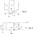
- the figure 8 is a vertical sectional view of the tool 9, at the level of the flattening plane 15. It can be seen in particular figure 8 the profile of the tooth 13, presenting a draft 21 and an undercut 23. Although figure 8 the cut is made at the level of the planar surface 15, the stall 17 and the front bevel have a similar structure.
- the flattening surface 15 has a clearance 21 forming with the cutting direction 25 of the tool 9 an angle ⁇ of about 5 ° to 8 °, and an undercut 23 forming with the advancing direction 25 of the tool 9 an angle ⁇ of about 10 ° to 14 °.
- the draft is 6 ° plus or minus 10 'over a length of 0.1 to 0.4 mm, preferably approximately 0.25 millimeters.
- the stall 17 has a draft 21 forming with the advancing direction 25 of the tool 9 an angle ⁇ of about 10 ° to 14 °, preferably 12 ° plus or minus 30 '.
- the front chamfer 19 has a draft 21 forming with the advancing direction 25 of the tool 9 an angle ⁇ of about 6 ° to 10 °, preferably 8 ° plus or minus 10 ', and an undercut 23 forming with the direction of advance 25 of the tool 9 an angle ⁇ of about 10 ° to 14 °, preferably 12 ° plus or minus 30 '.
- the tool 9 is here applied with a rotation speed of 8000 to 20000 revolutions per minute, and an advance of 300 to 600 millimeters per minute.
- the figure 9 shows in greater detail step 205 in which the milling tool 9 is used to machine the separating chamfer 3.
- the tool 9 is applied to the surface 1a, in particular in the longitudinal direction along the separating chamfer 3.
- the correspondence between the angles of the separating chamfer 3 of the separator 105 and the front bevel 19 of the tooth 13 makes it possible to obtain separating chamfer 3 in a single longitudinal passage.
- the separator blank 105 is turned over and clamped (step 207) on a support location 307, in particular on a table 301 whose platform is inclined at a potentially different corresponding angle. at the inclination of the surfaces 1c, 1d on the other side of the separator 105.
- the milling tool 9 is used for milling the surfaces 1c, 1d initially located on the opposite and inaccessible face of the separator 105.
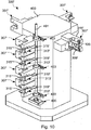
- the support 300 may be replaced by a support 300 'as shown in FIG. figure 10 .
- the support 300 ' comprises a tower 400 on which work locations 307' are mounted. Several locations 307 'can be vertically aligned on one face of the tower 400 and the locations 307' can be arranged on several sides of the tower 400.
- the separators 105 are arranged vertically and clamped in the locations 307 'for their machining. Fixing and clamping the separators 105 in the locations 307 'is carried out as in the previous embodiment by means of a fixed jaw 311' and a movable jaw 309 '. Fingers, bores and keys are also used.
- the tower 400 also comprises one or more rotary axes 401 vertical fixed on the tower via bearings 403.
- the rotary axis 401 is for example actuated by a rotary jack 405.
- the anti-vibration devices 313 'comprising an elastomeric pad 315' and an elastic member 319 'in the form of a leaf spring are fixed on the rotary axis 401 for example by means of screws so that the elastomeric pads 315' come into contact with the metal pieces or separators 105 by the rotation of the rotary axis 401.
- the rotary jack 405 is configured to apply a force so as to drive the elastomeric pad 315 'from 0.5mm to 3mm against the metal piece or separator 105.
- the tower 400 comprises 4 faces but a different number of faces can be envisaged. Moreover, the number of locations 307 'per face can also vary and be greater than four. Moreover, a single rotary axis is represented on the figure 10 but several rotary axes 401 can be arranged on the different faces (four in this case).
- the blank is pre-milled as before then placed and clamped in a location 307 'of the tower 400 by the movable jaw 309' and the fixed jaw 311 '.
- the metal part or separator 105 is then oriented vertically which allows better evacuation of chips during milling.
- the rotary axis 401 is positioned in a retracted position in which the elastomeric pad 315 'is moved away from the metal piece 105.
- the surfaces 1a and 1b oriented towards the fixed jaw 311' are then milled as previously described, the milling tool being identical to the tool described above.
- the rotary jack 405 actuates the rotary axis 401 so that the elastomeric pad 315 'comes into contact with the metal part 105 and in particular the surfaces 1a and 1b.
- the force applied by the rotary jack 405 causes a depression of 0.5 to 3 mm of the elastomeric buffer 315 '.
- the surfaces 1c and 1d oriented towards the movable jaw are milled.
- the use of a tower 400 as shown in the figure 10 allows elastomeric pads 315 'removable to be able to machine both sides of the separator 105 without having to debride it.
- the number of operations to perform the milling of the separator 105 is reduced, which reduces the time required for milling.
- the vertical orientation of the separators 105 on the tower allows better evacuation chips from milling.
- the milling method 200 is here used in the particular case of a machining process of a separator 105 of a motor vehicle lighting device 100, but can also be applied to obtaining a high surface area. reflectivity (above 85% in particular) on other types of aluminum metal parts to be machined, in particular with a thin portion, and terminated by a thin edge A.
Landscapes
- Engineering & Computer Science (AREA)
- Mechanical Engineering (AREA)
- Milling Processes (AREA)
Claims (15)
- Schwingungsdämpfende Vorrichtung für zu fräsenden Metallteilträger, die Folgendes umfasst:- einen Elastomerdämpfer (315), der dazu bestimmt ist, mit dem Metallteil in Berührung zu sein,- elastische Elemente (319), auf welchen der Elastomerdämpfer (315) angeordnet ist.
- Vorrichtung nach Anspruch 1, wobei die elastischen Elemente (319) dazu bestimmt sind, beim Verflanschen des Metallteils (105) verformt zu werden.
- Vorrichtung nach Anspruch 1 oder 2, dadurch gekennzeichnet, dass der Elastomerdämpfer (315) eine Härte zwischen 70 und 90 Shore hat.
- Vorrichtung nach einem der vorhergehenden Ansprüche, dadurch gekennzeichnet, dass die elastischen Elemente (319) eine Federklinge umfassen.
- Vorrichtung nach einem der Ansprüche 1 bis 3, dadurch gekennzeichnet, dass die elastischen Elemente (319) Schraubenfedern umfassen.
- Träger (300, 300') eines zu fräsenden Metallteils, dadurch gekennzeichnet, dass er Folgendes umfasst:- Verflanschungsmittel (309, 311) des Metallteils (105),- eine schwingungsdämpfende Vorrichtung (313) nach Anspruch 1.
- Träger (300) nach Anspruch 6, wobei die elastischen Elemente (319) dazu bestimmt sind, beim Verkeilen des Metallteils (105) verformt zu werden.
- Träger (300) nach Anspruch 7, dadurch gekennzeichnet, dass die Verflanschungsmittel des Metallteils (105) in Bezug auf die schwingungsdämpfende Vorrichtung (313) derart angeordnet sind, dass das Metallteil (105) im verflanschten Zustand den Elastomerdämpfer (315) 0,5 mm bis 3 mm eindrückt.
- Träger (300') nach Anspruch 6, wobei die elastischen Elemente (319') auf eine Drehachse (401) montiert sind und einen Dreharm bilden, der den Elastomerdämpfer (315') trägt und konfiguriert ist, um den Elastomerdämpfer (315') mit dem Metallteil (105) in Berührung zu bringen, wenn Letzteres in den Verflanschungsmitteln (309', 311') positioniert ist.
- Träger (300') nach Anspruch 6, wobei die Drehachse (401) durch einen Drehzylinder (405) betätigt wird, der ausgelegt ist, um eine Kraft derart anzulegen, dass der Elastomerdämpfer (315') um 0,5 mm bis 3 mm gegen das Metallteil (105) während des Fräsens des Metallteils (105) eingedrückt wird.
- Träger (300') nach Anspruch 9 oder 10, wobei die Rotationsachse (401) vertikal ausgerichtet ist.
- Fräsverfahren (200) eines Metallteils aus Aluminium zum Erhalten eines Oberflächenzustands mit hohem Reflexionsgrad, dadurch gekennzeichnet, dass es die folgenden Schritte aufweist:- das Metallteil wird auf einer schwingungsdämpfenden Vorrichtung (313), die einen Elastomerdämpfer (315) und elastische Elemente (319), die den Elastomerdämpfer (315) tragen, umfasst, verflanscht,- das Fräswerkzeug (9) wird über eine Oberfläche (1a, 1b, 1c, 1d) des Metallteils (105) geführt, wobei das Fräswerkzeug (9) einen einzigen Fräszahn (13) umfasst, der in Drehung mit einer Drehzahl zwischen 8000 und 20 000 Umdrehungen pro Minute angetrieben wird, wobei das Werkzeug (9) eine Vorlaufgeschwindigkeit von 300 bis 600 Millimeter pro Minute aufweist und der Zahn (13) Folgendes aufweist:- einen Schraubenwinkel gleich null,- einen Schneidwinkel gleich null,- eine Schlichtebene (15) mit einer Länge zwischen 1,3 und 1,5 Millimeter, die einen Freistich zwischen 5° und 8° hat und sich in einer Entfernung von 4 bis 8 Millimeter von der Rotationsachse (B) befindet.
- Verfahren nach Anspruch 7, dadurch gekennzeichnet, dass es außerdem einen zusätzlichen Schritt des vorausgehenden Fräsens (201) umfasst, der vor dem Schritt (205) ausgeführt wird, bei dem das Fräswerkzeug (9) über die Oberfläche (1a, 1b, 1c, 1d) geführt wird, wobei bei dem zusätzlichen Schritt (201) ein vorausgehendes Fräsen der Oberfläche derart ausgeführt wird, dass eine Überdicke von 1 bis 5 Mikrometer belassen wird.
- Verfahren nach Anspruch 7 oder 8, dadurch gekennzeichnet, dass bei dem Schritt (203), bei dem das Metallteil (105) auf dem Elastomerdämpfer (315) verflanscht wird, der Elastomerdämpfer (315) um etwa 0,5 bis 3 mm eingedrückt wird.
- Verfahren nach einem der Ansprüche 7 bis 9, dadurch gekennzeichnet, dass der Schritt (203), bei dem das Metallteil auf dem Elastomerdämpfer (315) verkeilt wird, das Metallteil (105) derart angeordnet wird, dass die Kante (A) einen Überhang von 0,05 und 0,2 Millimeter bildet.
Applications Claiming Priority (1)
| Application Number | Priority Date | Filing Date | Title |
|---|---|---|---|
| FR1352682A FR3003489B1 (fr) | 2013-03-25 | 2013-03-25 | Support anti-vibrations et procede de fraisage de piece metallique |
Publications (2)
| Publication Number | Publication Date |
|---|---|
| EP2801427A1 EP2801427A1 (de) | 2014-11-12 |
| EP2801427B1 true EP2801427B1 (de) | 2016-03-09 |
Family
ID=48521318
Family Applications (1)
| Application Number | Title | Priority Date | Filing Date |
|---|---|---|---|
| EP14161163.2A Active EP2801427B1 (de) | 2013-03-25 | 2014-03-21 | Schwingungsdämpfende Unterlage und Fräsverfahren eines Metallteils |
Country Status (3)
| Country | Link |
|---|---|
| EP (1) | EP2801427B1 (de) |
| ES (1) | ES2577113T3 (de) |
| FR (1) | FR3003489B1 (de) |
Families Citing this family (2)
| Publication number | Priority date | Publication date | Assignee | Title |
|---|---|---|---|---|
| FR3038537B1 (fr) * | 2015-07-10 | 2018-01-12 | Palumbo Industries | Support de piece metallique a fraiser |
| CN106112087A (zh) * | 2016-08-24 | 2016-11-16 | 浙江省平湖市工具厂 | 一种铣床的自动上料装置所用的外框后靠背板 |
Family Cites Families (4)
| Publication number | Priority date | Publication date | Assignee | Title |
|---|---|---|---|---|
| US4438599A (en) * | 1981-12-28 | 1984-03-27 | Cincinnati Milacron Inc. | Vibration damper for machine-carried workpiece |
| DE102005057175B4 (de) * | 2005-11-30 | 2009-03-26 | Siemens Ag | Verfahren zur Reduktion von Schwingungen eines Maschinenelements und/oder eines Werkstücks |
| US7793403B2 (en) * | 2005-12-27 | 2010-09-14 | Konica Minolta Opto, Inc. | Manufacturing method of optical component or molding die therefor |
| US8770567B2 (en) * | 2009-10-06 | 2014-07-08 | Quickmill Inc. | Cushioned support platform |
-
2013
- 2013-03-25 FR FR1352682A patent/FR3003489B1/fr not_active Expired - Fee Related
-
2014
- 2014-03-21 ES ES14161163.2T patent/ES2577113T3/es active Active
- 2014-03-21 EP EP14161163.2A patent/EP2801427B1/de active Active
Also Published As
| Publication number | Publication date |
|---|---|
| EP2801427A1 (de) | 2014-11-12 |
| FR3003489A1 (fr) | 2014-09-26 |
| ES2577113T3 (es) | 2016-07-13 |
| FR3003489B1 (fr) | 2015-05-22 |
Similar Documents
| Publication | Publication Date | Title |
|---|---|---|
| EP0035301B1 (de) | Verfahren zum Schleifen von zwei koaxialen konischen Oberflächen, Vorrichtung zur Durchführung des Verfahrens, Verwendung dieser Vorrichtung und so erhaltenes geschliffenes Werkstück | |
| EP0683002A1 (de) | Fräser | |
| FR2970664A1 (fr) | Foret modulaire avec bords de coupe en diamant | |
| EP2801427B1 (de) | Schwingungsdämpfende Unterlage und Fräsverfahren eines Metallteils | |
| WO2005065886A1 (fr) | Support de blocage pneumatique d'une lentille optique | |
| FR3101266A1 (fr) | Outil de sertissage et procede pour sertir les bords de deux pieces en tole | |
| EP2783778B1 (de) | Werkzeug und Fräsverfahren eines Metallteils | |
| FR2541155A1 (fr) | Fraise 2 tailles a tete de travail hemispherique formee sur le porte-plaquettes en forme de tige | |
| EP3183618B1 (de) | Zeiger einer armbanduhr | |
| EP3770698B1 (de) | Mineralstein vom monokristallinen typ mit einem kegel zur neuzentrierung eines zapfens, und sein herstellungsverfahren | |
| FR2819897A1 (fr) | Preforme de lentille ophtalmique | |
| EP1368149B2 (de) | Schneidwerkzeug | |
| EP1858664B1 (de) | Werkzeug und maschine für bearbeitungsvorgänge, die bei inversbetrieb eine gefahr darstellen | |
| EP0820821B1 (de) | Verfahren zum Ausschneiden eines Zuschnittteils aus einer Blechplatte | |
| FR2523010A1 (fr) | Procede de moletage coupant ou deformant, et des moyens de mise en oeuvre, destines a moleter ou rainurer des alesages ou portees cylindriques de pieces | |
| FR3057188B1 (fr) | Procede d'usinage d'une piece en materiau elastomere par tournage | |
| FR3038537A1 (fr) | Support de piece metallique a fraiser | |
| FR3014712A1 (fr) | Procede d'emboutissage de pieces presentant des angles saillants a faible rayon | |
| JP5369011B2 (ja) | 溝加工ツール及びこれを用いた薄膜太陽電池の溝加工方法 | |
| FR2796323A1 (fr) | Procede d'usinage par electroerosion et dispositif support de piece associe | |
| EP2187273B1 (de) | Bearbeitung von Werkstücken mit einem einzigen Klemmvorgang | |
| WO2012035511A1 (fr) | Jeu de plaquettes de coupe positive avec profil amélioré et porte-outil correspondant | |
| CA3009023A1 (en) | Method for sharpening a machining tip and corresponding sharpened tip | |
| FR2759929A1 (fr) | Lame de scie sauteuse | |
| FR2616695A1 (fr) | Procede de fabrication d'un outil de coupe par electro-erosion, electrode et outil correspondant |
Legal Events
| Date | Code | Title | Description |
|---|---|---|---|
| PUAI | Public reference made under article 153(3) epc to a published international application that has entered the european phase |
Free format text: ORIGINAL CODE: 0009012 |
|
| 17P | Request for examination filed |
Effective date: 20140321 |
|
| AK | Designated contracting states |
Kind code of ref document: A1 Designated state(s): AL AT BE BG CH CY CZ DE DK EE ES FI FR GB GR HR HU IE IS IT LI LT LU LV MC MK MT NL NO PL PT RO RS SE SI SK SM TR |
|
| AX | Request for extension of the european patent |
Extension state: BA ME |
|
| R17P | Request for examination filed (corrected) |
Effective date: 20150331 |
|
| RBV | Designated contracting states (corrected) |
Designated state(s): AL AT BE BG CH CY CZ DE DK EE ES FI FR GB GR HR HU IE IS IT LI LT LU LV MC MK MT NL NO PL PT RO RS SE SI SK SM TR |
|
| REG | Reference to a national code |
Ref country code: DE Ref legal event code: R079 Ref document number: 602014001026 Country of ref document: DE Free format text: PREVIOUS MAIN CLASS: B23C0003000000 Ipc: B23C0009000000 |
|
| GRAP | Despatch of communication of intention to grant a patent |
Free format text: ORIGINAL CODE: EPIDOSNIGR1 |
|
| RIC1 | Information provided on ipc code assigned before grant |
Ipc: B23Q 3/06 20060101ALI20150819BHEP Ipc: B23C 9/00 20060101AFI20150819BHEP |
|
| INTG | Intention to grant announced |
Effective date: 20150908 |
|
| GRAS | Grant fee paid |
Free format text: ORIGINAL CODE: EPIDOSNIGR3 |
|
| GRAA | (expected) grant |
Free format text: ORIGINAL CODE: 0009210 |
|
| AK | Designated contracting states |
Kind code of ref document: B1 Designated state(s): AL AT BE BG CH CY CZ DE DK EE ES FI FR GB GR HR HU IE IS IT LI LT LU LV MC MK MT NL NO PL PT RO RS SE SI SK SM TR |
|
| REG | Reference to a national code |
Ref country code: GB Ref legal event code: FG4D Free format text: NOT ENGLISH |
|
| REG | Reference to a national code |
Ref country code: AT Ref legal event code: REF Ref document number: 779125 Country of ref document: AT Kind code of ref document: T Effective date: 20160315 Ref country code: CH Ref legal event code: EP |
|
| REG | Reference to a national code |
Ref country code: IE Ref legal event code: FG4D Free format text: LANGUAGE OF EP DOCUMENT: FRENCH |
|
| REG | Reference to a national code |
Ref country code: FR Ref legal event code: PLFP Year of fee payment: 4 Ref country code: FR Ref legal event code: PLFP Year of fee payment: 3 |
|
| REG | Reference to a national code |
Ref country code: DE Ref legal event code: R096 Ref document number: 602014001026 Country of ref document: DE |
|
| REG | Reference to a national code |
Ref country code: LT Ref legal event code: MG4D |
|
| REG | Reference to a national code |
Ref country code: ES Ref legal event code: FG2A Ref document number: 2577113 Country of ref document: ES Kind code of ref document: T3 Effective date: 20160713 Ref country code: NL Ref legal event code: MP Effective date: 20160309 |
|
| PG25 | Lapsed in a contracting state [announced via postgrant information from national office to epo] |
Ref country code: NO Free format text: LAPSE BECAUSE OF FAILURE TO SUBMIT A TRANSLATION OF THE DESCRIPTION OR TO PAY THE FEE WITHIN THE PRESCRIBED TIME-LIMIT Effective date: 20160609 Ref country code: HR Free format text: LAPSE BECAUSE OF FAILURE TO SUBMIT A TRANSLATION OF THE DESCRIPTION OR TO PAY THE FEE WITHIN THE PRESCRIBED TIME-LIMIT Effective date: 20160309 Ref country code: GR Free format text: LAPSE BECAUSE OF FAILURE TO SUBMIT A TRANSLATION OF THE DESCRIPTION OR TO PAY THE FEE WITHIN THE PRESCRIBED TIME-LIMIT Effective date: 20160610 Ref country code: FI Free format text: LAPSE BECAUSE OF FAILURE TO SUBMIT A TRANSLATION OF THE DESCRIPTION OR TO PAY THE FEE WITHIN THE PRESCRIBED TIME-LIMIT Effective date: 20160309 |
|
| REG | Reference to a national code |
Ref country code: AT Ref legal event code: MK05 Ref document number: 779125 Country of ref document: AT Kind code of ref document: T Effective date: 20160309 |
|
| PG25 | Lapsed in a contracting state [announced via postgrant information from national office to epo] |
Ref country code: LV Free format text: LAPSE BECAUSE OF FAILURE TO SUBMIT A TRANSLATION OF THE DESCRIPTION OR TO PAY THE FEE WITHIN THE PRESCRIBED TIME-LIMIT Effective date: 20160309 Ref country code: NL Free format text: LAPSE BECAUSE OF FAILURE TO SUBMIT A TRANSLATION OF THE DESCRIPTION OR TO PAY THE FEE WITHIN THE PRESCRIBED TIME-LIMIT Effective date: 20160309 Ref country code: PL Free format text: LAPSE BECAUSE OF FAILURE TO SUBMIT A TRANSLATION OF THE DESCRIPTION OR TO PAY THE FEE WITHIN THE PRESCRIBED TIME-LIMIT Effective date: 20160309 Ref country code: SE Free format text: LAPSE BECAUSE OF FAILURE TO SUBMIT A TRANSLATION OF THE DESCRIPTION OR TO PAY THE FEE WITHIN THE PRESCRIBED TIME-LIMIT Effective date: 20160309 Ref country code: BE Free format text: LAPSE BECAUSE OF NON-PAYMENT OF DUE FEES Effective date: 20160331 Ref country code: LT Free format text: LAPSE BECAUSE OF FAILURE TO SUBMIT A TRANSLATION OF THE DESCRIPTION OR TO PAY THE FEE WITHIN THE PRESCRIBED TIME-LIMIT Effective date: 20160309 Ref country code: RS Free format text: LAPSE BECAUSE OF FAILURE TO SUBMIT A TRANSLATION OF THE DESCRIPTION OR TO PAY THE FEE WITHIN THE PRESCRIBED TIME-LIMIT Effective date: 20160309 |
|
| PG25 | Lapsed in a contracting state [announced via postgrant information from national office to epo] |
Ref country code: EE Free format text: LAPSE BECAUSE OF FAILURE TO SUBMIT A TRANSLATION OF THE DESCRIPTION OR TO PAY THE FEE WITHIN THE PRESCRIBED TIME-LIMIT Effective date: 20160309 Ref country code: IS Free format text: LAPSE BECAUSE OF FAILURE TO SUBMIT A TRANSLATION OF THE DESCRIPTION OR TO PAY THE FEE WITHIN THE PRESCRIBED TIME-LIMIT Effective date: 20160709 |
|
| PG25 | Lapsed in a contracting state [announced via postgrant information from national office to epo] |
Ref country code: CZ Free format text: LAPSE BECAUSE OF FAILURE TO SUBMIT A TRANSLATION OF THE DESCRIPTION OR TO PAY THE FEE WITHIN THE PRESCRIBED TIME-LIMIT Effective date: 20160309 Ref country code: SM Free format text: LAPSE BECAUSE OF FAILURE TO SUBMIT A TRANSLATION OF THE DESCRIPTION OR TO PAY THE FEE WITHIN THE PRESCRIBED TIME-LIMIT Effective date: 20160309 Ref country code: RO Free format text: LAPSE BECAUSE OF FAILURE TO SUBMIT A TRANSLATION OF THE DESCRIPTION OR TO PAY THE FEE WITHIN THE PRESCRIBED TIME-LIMIT Effective date: 20160309 Ref country code: PT Free format text: LAPSE BECAUSE OF FAILURE TO SUBMIT A TRANSLATION OF THE DESCRIPTION OR TO PAY THE FEE WITHIN THE PRESCRIBED TIME-LIMIT Effective date: 20160711 Ref country code: AT Free format text: LAPSE BECAUSE OF FAILURE TO SUBMIT A TRANSLATION OF THE DESCRIPTION OR TO PAY THE FEE WITHIN THE PRESCRIBED TIME-LIMIT Effective date: 20160309 Ref country code: SK Free format text: LAPSE BECAUSE OF FAILURE TO SUBMIT A TRANSLATION OF THE DESCRIPTION OR TO PAY THE FEE WITHIN THE PRESCRIBED TIME-LIMIT Effective date: 20160309 |
|
| REG | Reference to a national code |
Ref country code: DE Ref legal event code: R097 Ref document number: 602014001026 Country of ref document: DE |
|
| REG | Reference to a national code |
Ref country code: IE Ref legal event code: MM4A |
|
| PG25 | Lapsed in a contracting state [announced via postgrant information from national office to epo] |
Ref country code: IT Free format text: LAPSE BECAUSE OF FAILURE TO SUBMIT A TRANSLATION OF THE DESCRIPTION OR TO PAY THE FEE WITHIN THE PRESCRIBED TIME-LIMIT Effective date: 20160309 |
|
| PLBE | No opposition filed within time limit |
Free format text: ORIGINAL CODE: 0009261 |
|
| STAA | Information on the status of an ep patent application or granted ep patent |
Free format text: STATUS: NO OPPOSITION FILED WITHIN TIME LIMIT |
|
| PG25 | Lapsed in a contracting state [announced via postgrant information from national office to epo] |
Ref country code: DK Free format text: LAPSE BECAUSE OF FAILURE TO SUBMIT A TRANSLATION OF THE DESCRIPTION OR TO PAY THE FEE WITHIN THE PRESCRIBED TIME-LIMIT Effective date: 20160309 Ref country code: IE Free format text: LAPSE BECAUSE OF NON-PAYMENT OF DUE FEES Effective date: 20160321 |
|
| 26N | No opposition filed |
Effective date: 20161212 |
|
| PG25 | Lapsed in a contracting state [announced via postgrant information from national office to epo] |
Ref country code: BG Free format text: LAPSE BECAUSE OF FAILURE TO SUBMIT A TRANSLATION OF THE DESCRIPTION OR TO PAY THE FEE WITHIN THE PRESCRIBED TIME-LIMIT Effective date: 20160609 |
|
| REG | Reference to a national code |
Ref country code: FR Ref legal event code: PLFP Year of fee payment: 4 |
|
| PG25 | Lapsed in a contracting state [announced via postgrant information from national office to epo] |
Ref country code: SI Free format text: LAPSE BECAUSE OF FAILURE TO SUBMIT A TRANSLATION OF THE DESCRIPTION OR TO PAY THE FEE WITHIN THE PRESCRIBED TIME-LIMIT Effective date: 20160309 |
|
| PG25 | Lapsed in a contracting state [announced via postgrant information from national office to epo] |
Ref country code: MT Free format text: LAPSE BECAUSE OF FAILURE TO SUBMIT A TRANSLATION OF THE DESCRIPTION OR TO PAY THE FEE WITHIN THE PRESCRIBED TIME-LIMIT Effective date: 20160309 |
|
| REG | Reference to a national code |
Ref country code: CH Ref legal event code: PL |
|
| PG25 | Lapsed in a contracting state [announced via postgrant information from national office to epo] |
Ref country code: LI Free format text: LAPSE BECAUSE OF NON-PAYMENT OF DUE FEES Effective date: 20170331 Ref country code: CH Free format text: LAPSE BECAUSE OF NON-PAYMENT OF DUE FEES Effective date: 20170331 |
|
| REG | Reference to a national code |
Ref country code: FR Ref legal event code: PLFP Year of fee payment: 5 |
|
| PG25 | Lapsed in a contracting state [announced via postgrant information from national office to epo] |
Ref country code: HU Free format text: LAPSE BECAUSE OF FAILURE TO SUBMIT A TRANSLATION OF THE DESCRIPTION OR TO PAY THE FEE WITHIN THE PRESCRIBED TIME-LIMIT; INVALID AB INITIO Effective date: 20140321 |
|
| PG25 | Lapsed in a contracting state [announced via postgrant information from national office to epo] |
Ref country code: LU Free format text: LAPSE BECAUSE OF NON-PAYMENT OF DUE FEES Effective date: 20160321 Ref country code: MC Free format text: LAPSE BECAUSE OF FAILURE TO SUBMIT A TRANSLATION OF THE DESCRIPTION OR TO PAY THE FEE WITHIN THE PRESCRIBED TIME-LIMIT Effective date: 20160309 Ref country code: MK Free format text: LAPSE BECAUSE OF FAILURE TO SUBMIT A TRANSLATION OF THE DESCRIPTION OR TO PAY THE FEE WITHIN THE PRESCRIBED TIME-LIMIT Effective date: 20160309 Ref country code: CY Free format text: LAPSE BECAUSE OF FAILURE TO SUBMIT A TRANSLATION OF THE DESCRIPTION OR TO PAY THE FEE WITHIN THE PRESCRIBED TIME-LIMIT Effective date: 20160309 |
|
| PG25 | Lapsed in a contracting state [announced via postgrant information from national office to epo] |
Ref country code: AL Free format text: LAPSE BECAUSE OF FAILURE TO SUBMIT A TRANSLATION OF THE DESCRIPTION OR TO PAY THE FEE WITHIN THE PRESCRIBED TIME-LIMIT Effective date: 20160309 Ref country code: TR Free format text: LAPSE BECAUSE OF FAILURE TO SUBMIT A TRANSLATION OF THE DESCRIPTION OR TO PAY THE FEE WITHIN THE PRESCRIBED TIME-LIMIT Effective date: 20160309 |
|
| GBPC | Gb: european patent ceased through non-payment of renewal fee |
Effective date: 20180321 |
|
| PG25 | Lapsed in a contracting state [announced via postgrant information from national office to epo] |
Ref country code: GB Free format text: LAPSE BECAUSE OF NON-PAYMENT OF DUE FEES Effective date: 20180321 |
|
| PGFP | Annual fee paid to national office [announced via postgrant information from national office to epo] |
Ref country code: DE Payment date: 20200402 Year of fee payment: 7 |
|
| REG | Reference to a national code |
Ref country code: DE Ref legal event code: R119 Ref document number: 602014001026 Country of ref document: DE |
|
| PG25 | Lapsed in a contracting state [announced via postgrant information from national office to epo] |
Ref country code: DE Free format text: LAPSE BECAUSE OF NON-PAYMENT OF DUE FEES Effective date: 20211001 |
|
| PGFP | Annual fee paid to national office [announced via postgrant information from national office to epo] |
Ref country code: ES Payment date: 20220401 Year of fee payment: 9 |
|
| REG | Reference to a national code |
Ref country code: ES Ref legal event code: FD2A Effective date: 20240528 |
|
| PG25 | Lapsed in a contracting state [announced via postgrant information from national office to epo] |
Ref country code: ES Free format text: LAPSE BECAUSE OF NON-PAYMENT OF DUE FEES Effective date: 20230322 |
|
| PG25 | Lapsed in a contracting state [announced via postgrant information from national office to epo] |
Ref country code: ES Free format text: LAPSE BECAUSE OF NON-PAYMENT OF DUE FEES Effective date: 20230322 |
|
| PGFP | Annual fee paid to national office [announced via postgrant information from national office to epo] |
Ref country code: FR Payment date: 20250326 Year of fee payment: 12 |