EP2801497A2 - Dispositif de charge et procédé de fonctionnement d'un dispositif de charge - Google Patents
Dispositif de charge et procédé de fonctionnement d'un dispositif de charge Download PDFInfo
- Publication number
- EP2801497A2 EP2801497A2 EP13005530.4A EP13005530A EP2801497A2 EP 2801497 A2 EP2801497 A2 EP 2801497A2 EP 13005530 A EP13005530 A EP 13005530A EP 2801497 A2 EP2801497 A2 EP 2801497A2
- Authority
- EP
- European Patent Office
- Prior art keywords
- charging
- voltage
- lwn
- correction
- converter
- Prior art date
- Legal status (The legal status is an assumption and is not a legal conclusion. Google has not performed a legal analysis and makes no representation as to the accuracy of the status listed.)
- Granted
Links
Images
Classifications
-
- H—ELECTRICITY
- H02—GENERATION; CONVERSION OR DISTRIBUTION OF ELECTRIC POWER
- H02J—ELECTRIC POWER NETWORKS; CIRCUIT ARRANGEMENTS OR SYSTEMS FOR SUPPLYING OR DISTRIBUTING ELECTRIC POWER; SYSTEMS FOR STORING ELECTRIC ENERGY
- H02J7/00—Circuit arrangements for charging or discharging batteries or for supplying loads from batteries
- H02J7/14—Circuit arrangements for charging or discharging batteries or for supplying loads from batteries for charging batteries from dynamo-electric generators driven at varying speed, e.g. on vehicle
- H02J7/1423—Circuit arrangements for charging or discharging batteries or for supplying loads from batteries for charging batteries from dynamo-electric generators driven at varying speed, e.g. on vehicle with multiple batteries
-
- B—PERFORMING OPERATIONS; TRANSPORTING
- B60—VEHICLES IN GENERAL
- B60L—PROPULSION OF ELECTRICALLY-PROPELLED VEHICLES; SUPPLYING ELECTRIC POWER FOR AUXILIARY EQUIPMENT OF ELECTRICALLY-PROPELLED VEHICLES; ELECTRODYNAMIC BRAKE SYSTEMS FOR VEHICLES IN GENERAL; MAGNETIC SUSPENSION OR LEVITATION FOR VEHICLES; MONITORING OPERATING VARIABLES OF ELECTRICALLY-PROPELLED VEHICLES; ELECTRIC SAFETY DEVICES FOR ELECTRICALLY-PROPELLED VEHICLES
- B60L53/00—Methods of charging batteries, specially adapted for electric vehicles; Charging stations or on-board charging equipment therefor; Exchange of energy storage elements in electric vehicles
- B60L53/20—Methods of charging batteries, specially adapted for electric vehicles; Charging stations or on-board charging equipment therefor; Exchange of energy storage elements in electric vehicles characterised by converters located in the vehicle
- B60L53/22—Constructional details or arrangements of charging converters specially adapted for charging electric vehicles
-
- B—PERFORMING OPERATIONS; TRANSPORTING
- B60—VEHICLES IN GENERAL
- B60L—PROPULSION OF ELECTRICALLY-PROPELLED VEHICLES; SUPPLYING ELECTRIC POWER FOR AUXILIARY EQUIPMENT OF ELECTRICALLY-PROPELLED VEHICLES; ELECTRODYNAMIC BRAKE SYSTEMS FOR VEHICLES IN GENERAL; MAGNETIC SUSPENSION OR LEVITATION FOR VEHICLES; MONITORING OPERATING VARIABLES OF ELECTRICALLY-PROPELLED VEHICLES; ELECTRIC SAFETY DEVICES FOR ELECTRICALLY-PROPELLED VEHICLES
- B60L58/00—Methods or circuit arrangements for monitoring or controlling batteries or fuel cells, specially adapted for electric vehicles
- B60L58/10—Methods or circuit arrangements for monitoring or controlling batteries or fuel cells, specially adapted for electric vehicles for monitoring or controlling batteries
- B60L58/18—Methods or circuit arrangements for monitoring or controlling batteries or fuel cells, specially adapted for electric vehicles for monitoring or controlling batteries of two or more battery modules
- B60L58/20—Methods or circuit arrangements for monitoring or controlling batteries or fuel cells, specially adapted for electric vehicles for monitoring or controlling batteries of two or more battery modules having different nominal voltages
-
- H—ELECTRICITY
- H02—GENERATION; CONVERSION OR DISTRIBUTION OF ELECTRIC POWER
- H02J—ELECTRIC POWER NETWORKS; CIRCUIT ARRANGEMENTS OR SYSTEMS FOR SUPPLYING OR DISTRIBUTING ELECTRIC POWER; SYSTEMS FOR STORING ELECTRIC ENERGY
- H02J7/00—Circuit arrangements for charging or discharging batteries or for supplying loads from batteries
- H02J7/34—Parallel operation in networks using both storage and other DC sources, e.g. providing buffering
- H02J7/342—The other DC source being a battery actively interacting with the first one, i.e. battery to battery charging
-
- B—PERFORMING OPERATIONS; TRANSPORTING
- B60—VEHICLES IN GENERAL
- B60L—PROPULSION OF ELECTRICALLY-PROPELLED VEHICLES; SUPPLYING ELECTRIC POWER FOR AUXILIARY EQUIPMENT OF ELECTRICALLY-PROPELLED VEHICLES; ELECTRODYNAMIC BRAKE SYSTEMS FOR VEHICLES IN GENERAL; MAGNETIC SUSPENSION OR LEVITATION FOR VEHICLES; MONITORING OPERATING VARIABLES OF ELECTRICALLY-PROPELLED VEHICLES; ELECTRIC SAFETY DEVICES FOR ELECTRICALLY-PROPELLED VEHICLES
- B60L2210/00—Converter types
- B60L2210/10—DC to DC converters
-
- B—PERFORMING OPERATIONS; TRANSPORTING
- B60—VEHICLES IN GENERAL
- B60L—PROPULSION OF ELECTRICALLY-PROPELLED VEHICLES; SUPPLYING ELECTRIC POWER FOR AUXILIARY EQUIPMENT OF ELECTRICALLY-PROPELLED VEHICLES; ELECTRODYNAMIC BRAKE SYSTEMS FOR VEHICLES IN GENERAL; MAGNETIC SUSPENSION OR LEVITATION FOR VEHICLES; MONITORING OPERATING VARIABLES OF ELECTRICALLY-PROPELLED VEHICLES; ELECTRIC SAFETY DEVICES FOR ELECTRICALLY-PROPELLED VEHICLES
- B60L2240/00—Control parameters of input or output; Target parameters
- B60L2240/40—Drive Train control parameters
- B60L2240/54—Drive Train control parameters related to batteries
- B60L2240/547—Voltage
-
- B—PERFORMING OPERATIONS; TRANSPORTING
- B60—VEHICLES IN GENERAL
- B60L—PROPULSION OF ELECTRICALLY-PROPELLED VEHICLES; SUPPLYING ELECTRIC POWER FOR AUXILIARY EQUIPMENT OF ELECTRICALLY-PROPELLED VEHICLES; ELECTRODYNAMIC BRAKE SYSTEMS FOR VEHICLES IN GENERAL; MAGNETIC SUSPENSION OR LEVITATION FOR VEHICLES; MONITORING OPERATING VARIABLES OF ELECTRICALLY-PROPELLED VEHICLES; ELECTRIC SAFETY DEVICES FOR ELECTRICALLY-PROPELLED VEHICLES
- B60L2240/00—Control parameters of input or output; Target parameters
- B60L2240/40—Drive Train control parameters
- B60L2240/54—Drive Train control parameters related to batteries
- B60L2240/549—Current
-
- Y—GENERAL TAGGING OF NEW TECHNOLOGICAL DEVELOPMENTS; GENERAL TAGGING OF CROSS-SECTIONAL TECHNOLOGIES SPANNING OVER SEVERAL SECTIONS OF THE IPC; TECHNICAL SUBJECTS COVERED BY FORMER USPC CROSS-REFERENCE ART COLLECTIONS [XRACs] AND DIGESTS
- Y02—TECHNOLOGIES OR APPLICATIONS FOR MITIGATION OR ADAPTATION AGAINST CLIMATE CHANGE
- Y02T—CLIMATE CHANGE MITIGATION TECHNOLOGIES RELATED TO TRANSPORTATION
- Y02T10/00—Road transport of goods or passengers
- Y02T10/60—Other road transportation technologies with climate change mitigation effect
- Y02T10/70—Energy storage systems for electromobility, e.g. batteries
-
- Y—GENERAL TAGGING OF NEW TECHNOLOGICAL DEVELOPMENTS; GENERAL TAGGING OF CROSS-SECTIONAL TECHNOLOGIES SPANNING OVER SEVERAL SECTIONS OF THE IPC; TECHNICAL SUBJECTS COVERED BY FORMER USPC CROSS-REFERENCE ART COLLECTIONS [XRACs] AND DIGESTS
- Y02—TECHNOLOGIES OR APPLICATIONS FOR MITIGATION OR ADAPTATION AGAINST CLIMATE CHANGE
- Y02T—CLIMATE CHANGE MITIGATION TECHNOLOGIES RELATED TO TRANSPORTATION
- Y02T10/00—Road transport of goods or passengers
- Y02T10/60—Other road transportation technologies with climate change mitigation effect
- Y02T10/7072—Electromobility specific charging systems or methods for batteries, ultracapacitors, supercapacitors or double-layer capacitors
-
- Y—GENERAL TAGGING OF NEW TECHNOLOGICAL DEVELOPMENTS; GENERAL TAGGING OF CROSS-SECTIONAL TECHNOLOGIES SPANNING OVER SEVERAL SECTIONS OF THE IPC; TECHNICAL SUBJECTS COVERED BY FORMER USPC CROSS-REFERENCE ART COLLECTIONS [XRACs] AND DIGESTS
- Y02—TECHNOLOGIES OR APPLICATIONS FOR MITIGATION OR ADAPTATION AGAINST CLIMATE CHANGE
- Y02T—CLIMATE CHANGE MITIGATION TECHNOLOGIES RELATED TO TRANSPORTATION
- Y02T10/00—Road transport of goods or passengers
- Y02T10/60—Other road transportation technologies with climate change mitigation effect
- Y02T10/72—Electric energy management in electromobility
-
- Y—GENERAL TAGGING OF NEW TECHNOLOGICAL DEVELOPMENTS; GENERAL TAGGING OF CROSS-SECTIONAL TECHNOLOGIES SPANNING OVER SEVERAL SECTIONS OF THE IPC; TECHNICAL SUBJECTS COVERED BY FORMER USPC CROSS-REFERENCE ART COLLECTIONS [XRACs] AND DIGESTS
- Y02—TECHNOLOGIES OR APPLICATIONS FOR MITIGATION OR ADAPTATION AGAINST CLIMATE CHANGE
- Y02T—CLIMATE CHANGE MITIGATION TECHNOLOGIES RELATED TO TRANSPORTATION
- Y02T90/00—Enabling technologies or technologies with a potential or indirect contribution to GHG emissions mitigation
- Y02T90/10—Technologies relating to charging of electric vehicles
- Y02T90/14—Plug-in electric vehicles
Definitions
- the invention relates to a method for operating a charging device with a plurality of charging converters according to the preamble of patent claim 1 and to a charging device for carrying out the method according to patent claim 6.
- a charging device which can include several charging converters.
- the individual charge converters are connected to a DC voltage, which is provided by energy stores of a DC network.
- the charge converters convert the DC voltage present on the input side into a low-voltage vehicle electrical system voltage, so that the output transducers serve as a voltage supply for the low-voltage vehicle electrical system.
- the invention has for its object to provide a method for operating a charging device with multiple charging converters, with which the charging currents fed by the charging converters in the low-voltage electrical system are as equal as possible.
- a common output-side desired charging voltage is predetermined by a control of all charging converters and each charging converter cyclically measures its output-side charging current and, depending on the output-side charging current, applies the nominal charging voltage with a correction voltage value, so that the output side results in a correspondingly corrected charging voltage.
- the correction of the output-side charging voltage can be carried out at each charging converter by means of an analog control or else by digital control elements.
- Each measured output-side charging current is preferably assigned a correction voltage value which is dependent on the magnitude of the charging current.
- the plurality of different correction voltage values, which are assigned to different charging current values can be stored in a characteristic curve or characteristics map memory.
- the correction of the output-side charging voltage results in an equal distribution for the charging currents of the individual charging converters. For example, if the charging current is higher in a first charging converter than in a second charging converter, the output charging voltage of the first charging converter is reduced by a correction voltage value that is greater than a possible correction voltage value for the second charging converter. If the charging current at the second charging converter is at a predetermined desired value for the intended setpoint charging voltage, then a voltage correction can be omitted.
- the internal resistance of the respective charging converter can be changed accordingly as a function of the predetermined correction voltage value.
- the correction of the charging voltage can also be done by means of a voltage adder or other voltage control device.
- Correction voltage values can be stored as a function of different parameters in such a map memory. For example, the values of charging current correction voltage characteristics specified for a different number of intended charging converters may be stored. In this case, different charging current correction voltage characteristics can be provided, which are dependent on the respective predetermined desired charging voltage.
- each charging converter can be assigned a specific desired charging current in a characteristic map memory. If deviations from the desired charging current occur in a charging converter, then this automatically corrects its output charging voltage with a correction voltage value, which can preferably be taken from a characteristic map memory.
- the invention has the further object of providing a charging device which is suitable for carrying out the method according to the invention and is suitable for use in different low-voltage on-board networks with different power requirements.
- each charging converter has a current measuring device for the charge current fed by it into a low-voltage electrical system, that each charging converter determines a correction voltage value as a function of the measured charging current for adjusting the charging voltage applied to the low-voltage electrical system and the Setting the charging voltage to a controllable voltage source.
- the setting of the charging voltage can be carried out in such a way that a relatively high charging current leads to a greater reduction of the output-side charging voltage at the charging converter.
- a slightly lower charging current to a charging converter leads to a smaller reduction of the output side charging voltage.
- a cyclical repetition of the voltage correction at the output-side charging voltage of each charging converter results in that the charging currents of the charging converters gradually adjust to a uniform same value.
- Each charge converter may include a characteristic map memory or a characteristic curve memory in which charging current-dependent correction voltage values are stored in association with different desired charging voltage values and with different numbers of charging converters provided in the charging device.
- each load converter can automatically make the adjustment of its output-side charging current so that an alignment of all charging currents of the charging converter takes place.
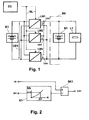
- the block diagram of FIG. 1 comprises a plurality of charging converters LW1 to LWn, which supply a low-voltage onboard power supply NV with energy, which, in simplified terms, consists of an energy store B1 and a load collective L1.
- the load transducers LW1 to LWn are connected to a power source E1, which applies a DC voltage to the parallel-connected inputs of the charge converters LW1 to LWn.
- a controller CU is connected via control lines SL to control inputs of the charging converters LW1 to LWn, via which the controller CU predefines a desired charging voltage to the charging converters LW1 to LWn.
- the energy storage E1 can also be provided to supply the electric drive of a motor vehicle, while the provided in the low-voltage electrical system NV energy storage B1 can be configured as a conventional low-voltage electrical system battery.
- the charging converters LW1 to LWn convert the DC voltage UE1 applied to them on the input side into output voltages UA1 to UAn. Under ideal conditions without component tolerances and without different line resistances, the output-side charging voltages UA1 to UAn would have the value of the nominal charging voltage predetermined by the controller CU.
- each of the charging voltages UA1 to UAn is corrected as a function of the charging current IA1 to IAn respectively measured at the charging converter LW1 to LWn.
- the charging converter LW1 how the correction of the charging voltage UA1 is performed.
- the predetermined charging voltage Us given by the control CU is applied to a correction voltage value which depends on the respective charging current.
- the output side charging current IA1 of the charging converter LW1 is measured, and depending on the measured current value, an associated correction voltage value Uk1 is read from a characteristic map memory K1. This correction voltage value Uk1 is linked to the desired charging voltage Us in a voltage correction device SK1.
- the correction voltage value Uk1 is subtracted from the predetermined value for the desired charging voltage Us, so that there is a comparison with the predetermined desired charging voltage reduced output side charging voltage UA1 at the load converter LW1.
- the correction of the output-side charging voltage UA1 is carried out cyclically, that is to say that the charging current IA1 is measured in repeated measurements and a correction voltage value is interrogated from the characteristic diagram K1 and used for voltage correction.
- Such a cyclic voltage correction is performed internally in each of the charging converters LW1 to LWn. This adjusts the charging currents IA1 to IAn for all charging converters LW1 to LWn.
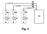
- the voltage correction devices SK1 to SKn of the charge converters LW1 to LWn can be controllable voltage sources that operate analog or digital. Which type of controllable voltage source or adjustable voltage source is used in each case can be selected according to the application. For example, voltage sources with variable internal resistance can also be used for this, as in the equivalent circuit diagram of FIG FIG. 3 is provided.
- Each load converter LW1 to LWn includes a voltage source providing a voltage U1 to Un. Via variable internal resistances Rv1 to Rvn, the Output voltages UA1 to UAn be corrected so that the same output-side charging currents IA1 to IAn flow into the low-voltage electrical system NV.
Landscapes
- Engineering & Computer Science (AREA)
- Power Engineering (AREA)
- Transportation (AREA)
- Mechanical Engineering (AREA)
- Life Sciences & Earth Sciences (AREA)
- Sustainable Development (AREA)
- Sustainable Energy (AREA)
- Charge And Discharge Circuits For Batteries Or The Like (AREA)
- Secondary Cells (AREA)
- Electric Propulsion And Braking For Vehicles (AREA)
Applications Claiming Priority (1)
| Application Number | Priority Date | Filing Date | Title |
|---|---|---|---|
| DE102013007185.2A DE102013007185A1 (de) | 2013-04-25 | 2013-04-25 | Ladeeinrichtung und Verfahren zum Betrieb einer Ladeeinrichtung |
Publications (3)
| Publication Number | Publication Date |
|---|---|
| EP2801497A2 true EP2801497A2 (fr) | 2014-11-12 |
| EP2801497A3 EP2801497A3 (fr) | 2015-09-16 |
| EP2801497B1 EP2801497B1 (fr) | 2020-04-22 |
Family
ID=49709431
Family Applications (1)
| Application Number | Title | Priority Date | Filing Date |
|---|---|---|---|
| EP13005530.4A Active EP2801497B1 (fr) | 2013-04-25 | 2013-11-28 | Dispositif de charge et procédé de fonctionnement d'un dispositif de charge |
Country Status (2)
| Country | Link |
|---|---|
| EP (1) | EP2801497B1 (fr) |
| DE (1) | DE102013007185A1 (fr) |
Families Citing this family (1)
| Publication number | Priority date | Publication date | Assignee | Title |
|---|---|---|---|---|
| CN113022342B (zh) * | 2016-11-03 | 2022-08-09 | 上海追日电气有限公司 | 一种智能功率分配快速充电机及其控制方法 |
Family Cites Families (8)
| Publication number | Priority date | Publication date | Assignee | Title |
|---|---|---|---|---|
| US5352968A (en) * | 1992-05-28 | 1994-10-04 | Apple Computer, Inc. | Battery charge state determination |
| US5783799A (en) * | 1996-01-11 | 1998-07-21 | Illinois Tool Works Inc. | Series resonant converter, and method and apparatus for control thereof |
| US6917182B2 (en) * | 2003-07-24 | 2005-07-12 | Motorola, Inc. | Method and system for providing induction charging having improved efficiency |
| FI118656B (fi) * | 2006-05-05 | 2008-01-31 | Finnish Electric Vehicle Techn | Menetelmä ja laitteisto akkukennojen hoitamiseksi |
| US20080238357A1 (en) * | 2007-03-26 | 2008-10-02 | Bourilkov Jordan T | Ultra fast battery charger with battery sensing |
| JP5647057B2 (ja) * | 2010-05-19 | 2014-12-24 | 株式会社日立製作所 | 充電装置、充電制御ユニット及び充電制御方法 |
| CN103209856B (zh) * | 2010-11-10 | 2015-05-27 | 丰田自动车株式会社 | 电动车辆的电源系统及其控制方法以及电动车辆 |
| DE102011079430A1 (de) * | 2011-07-19 | 2013-01-24 | Siemens Aktiengesellschaft | DC-Ladestation zum Aufladen mehrerer Energiespeichereinrichtungen |
-
2013
- 2013-04-25 DE DE102013007185.2A patent/DE102013007185A1/de not_active Withdrawn
- 2013-11-28 EP EP13005530.4A patent/EP2801497B1/fr active Active
Non-Patent Citations (1)
| Title |
|---|
| None |
Also Published As
| Publication number | Publication date |
|---|---|
| DE102013007185A1 (de) | 2014-10-30 |
| EP2801497B1 (fr) | 2020-04-22 |
| EP2801497A3 (fr) | 2015-09-16 |
Similar Documents
| Publication | Publication Date | Title |
|---|---|---|
| DE102017118610A1 (de) | Gleichstromumwandlung für elektrifizierte Fahrzeuge mit verteilter Steuerung | |
| DE102017118606A1 (de) | Leistungsumwandlung für Niederspannungsbus in elektrifiziertem Fahrzeug | |
| EP3207585B2 (fr) | Procédé de fonctionnement d'un réseau électrique, notamment d'un réseau électrique d'engin nautique | |
| EP1784910B1 (fr) | Regulateur de tension a protection contre les surtensions | |
| EP3539816B1 (fr) | Procédé de charge d'un accumulateur d'énergie d'un véhicule à l'aide d'un dispositif de charge modulaire à degré de rendement élevé | |
| DE102011079430A1 (de) | DC-Ladestation zum Aufladen mehrerer Energiespeichereinrichtungen | |
| DE102017222975A1 (de) | Steuervorrichtung, Gleichgewichtskorrekturvorrichtung, elektrisches Speichersystem und Einrichtung | |
| DE102014220005A1 (de) | Verfahren für eine Zellsymmetrierung einer Mehrzahl von Batteriezellen und Batteriesystem zum Durchführen eines derartigen Verfahrens | |
| DE102012015921A1 (de) | Energieversorgungseinheit, insbesondere für ein Kraftfahrzeug | |
| DE112015002996T5 (de) | Balancing-korrektur-steuervorrichtung, balancing-korrektur-system und elektrisches speichersystem | |
| DE112014007109T5 (de) | Fahrzeuggleichspannungswandler | |
| EP4052321B1 (fr) | Procédé pour charger et/ou décharger un accumulateur d'énergie rechargeable | |
| EP3371847A1 (fr) | Procédé pour faire fonctionner une batterie et batterie | |
| EP4470088A1 (fr) | Procédé et dispositif de charge d'une batterie à cellules multiples | |
| WO2022111894A1 (fr) | Agencement de convertisseur cc, système électrique embarqué pour véhicule électrique et procédé de fonctionnement d'un agencement de convertisseur cc | |
| DE102017222217A1 (de) | Verfahren zum Laden einer Batterie, Auswerteeinheit eines Stromnetzes und Automobil | |
| EP3592597B1 (fr) | Sous-marin et procédé pour faire fonctionner un système d'entraînement électrique alimenté par batterie d'un sous-marin | |
| WO2006045654A1 (fr) | Dispositif d'alimentation en tension comprenant plusieurs generateurs connectes en parallele | |
| DE112022002486T5 (de) | Einstellung der umrichterklemmenspannung in leistungssystem | |
| EP2801497B1 (fr) | Dispositif de charge et procédé de fonctionnement d'un dispositif de charge | |
| DE102020110155A1 (de) | Batteriewiderstandsmessvorrichtung | |
| DE102015224090B4 (de) | Schaltungsanordnung zur Spannungsversorgung eines Traktionsnetzes eines elektrischen Antriebsstranges | |
| DE102008040696A1 (de) | Verfahren zur Regelung der Ausgangsspannung eines Generators in einem Kraftfahrzeug | |
| EP1747601A2 (fr) | Egalisation de charge d'une batterie divisee en blocs | |
| WO2019020446A1 (fr) | Procédé pour faire fonctionner l'ensemble d'un réseau de bord électrique, unité de commande et véhicule à moteur |
Legal Events
| Date | Code | Title | Description |
|---|---|---|---|
| PUAI | Public reference made under article 153(3) epc to a published international application that has entered the european phase |
Free format text: ORIGINAL CODE: 0009012 |
|
| 17P | Request for examination filed |
Effective date: 20131128 |
|
| AK | Designated contracting states |
Kind code of ref document: A2 Designated state(s): AL AT BE BG CH CY CZ DE DK EE ES FI FR GB GR HR HU IE IS IT LI LT LU LV MC MK MT NL NO PL PT RO RS SE SI SK SM TR |
|
| AX | Request for extension of the european patent |
Extension state: BA ME |
|
| PUAL | Search report despatched |
Free format text: ORIGINAL CODE: 0009013 |
|
| AK | Designated contracting states |
Kind code of ref document: A3 Designated state(s): AL AT BE BG CH CY CZ DE DK EE ES FI FR GB GR HR HU IE IS IT LI LT LU LV MC MK MT NL NO PL PT RO RS SE SI SK SM TR |
|
| AX | Request for extension of the european patent |
Extension state: BA ME |
|
| RIC1 | Information provided on ipc code assigned before grant |
Ipc: H02J 1/04 20060101ALI20150811BHEP Ipc: B60L 11/18 20060101AFI20150811BHEP Ipc: B60L 9/00 20060101ALI20150811BHEP |
|
| R17P | Request for examination filed (corrected) |
Effective date: 20160316 |
|
| RAP1 | Party data changed (applicant data changed or rights of an application transferred) |
Owner name: MAN TRUCK & BUS SE |
|
| REG | Reference to a national code |
Ref country code: DE Ref legal event code: R079 Ref document number: 502013014605 Country of ref document: DE Free format text: PREVIOUS MAIN CLASS: B60L0011180000 Ipc: B60L0009000000 |
|
| GRAP | Despatch of communication of intention to grant a patent |
Free format text: ORIGINAL CODE: EPIDOSNIGR1 |
|
| STAA | Information on the status of an ep patent application or granted ep patent |
Free format text: STATUS: GRANT OF PATENT IS INTENDED |
|
| RIC1 | Information provided on ipc code assigned before grant |
Ipc: B60L 53/22 20190101ALI20191025BHEP Ipc: H02J 7/00 20060101ALI20191025BHEP Ipc: B60L 58/12 20190101ALI20191025BHEP Ipc: H02J 7/14 20060101ALI20191025BHEP Ipc: H02J 1/04 20060101ALI20191025BHEP Ipc: B60L 9/00 20190101AFI20191025BHEP Ipc: B60L 58/20 20190101ALI20191025BHEP |
|
| INTG | Intention to grant announced |
Effective date: 20191111 |
|
| GRAS | Grant fee paid |
Free format text: ORIGINAL CODE: EPIDOSNIGR3 |
|
| GRAA | (expected) grant |
Free format text: ORIGINAL CODE: 0009210 |
|
| STAA | Information on the status of an ep patent application or granted ep patent |
Free format text: STATUS: THE PATENT HAS BEEN GRANTED |
|
| AK | Designated contracting states |
Kind code of ref document: B1 Designated state(s): AL AT BE BG CH CY CZ DE DK EE ES FI FR GB GR HR HU IE IS IT LI LT LU LV MC MK MT NL NO PL PT RO RS SE SI SK SM TR |
|
| REG | Reference to a national code |
Ref country code: GB Ref legal event code: FG4D Free format text: NOT ENGLISH |
|
| REG | Reference to a national code |
Ref country code: CH Ref legal event code: EP |
|
| REG | Reference to a national code |
Ref country code: DE Ref legal event code: R096 Ref document number: 502013014605 Country of ref document: DE |
|
| REG | Reference to a national code |
Ref country code: IE Ref legal event code: FG4D Free format text: LANGUAGE OF EP DOCUMENT: GERMAN |
|
| REG | Reference to a national code |
Ref country code: AT Ref legal event code: REF Ref document number: 1259645 Country of ref document: AT Kind code of ref document: T Effective date: 20200515 |
|
| REG | Reference to a national code |
Ref country code: LT Ref legal event code: MG4D |
|
| REG | Reference to a national code |
Ref country code: NL Ref legal event code: MP Effective date: 20200422 |
|
| PG25 | Lapsed in a contracting state [announced via postgrant information from national office to epo] |
Ref country code: SE Free format text: LAPSE BECAUSE OF FAILURE TO SUBMIT A TRANSLATION OF THE DESCRIPTION OR TO PAY THE FEE WITHIN THE PRESCRIBED TIME-LIMIT Effective date: 20200422 Ref country code: IS Free format text: LAPSE BECAUSE OF FAILURE TO SUBMIT A TRANSLATION OF THE DESCRIPTION OR TO PAY THE FEE WITHIN THE PRESCRIBED TIME-LIMIT Effective date: 20200822 Ref country code: PT Free format text: LAPSE BECAUSE OF FAILURE TO SUBMIT A TRANSLATION OF THE DESCRIPTION OR TO PAY THE FEE WITHIN THE PRESCRIBED TIME-LIMIT Effective date: 20200824 Ref country code: NL Free format text: LAPSE BECAUSE OF FAILURE TO SUBMIT A TRANSLATION OF THE DESCRIPTION OR TO PAY THE FEE WITHIN THE PRESCRIBED TIME-LIMIT Effective date: 20200422 Ref country code: LT Free format text: LAPSE BECAUSE OF FAILURE TO SUBMIT A TRANSLATION OF THE DESCRIPTION OR TO PAY THE FEE WITHIN THE PRESCRIBED TIME-LIMIT Effective date: 20200422 Ref country code: GR Free format text: LAPSE BECAUSE OF FAILURE TO SUBMIT A TRANSLATION OF THE DESCRIPTION OR TO PAY THE FEE WITHIN THE PRESCRIBED TIME-LIMIT Effective date: 20200723 Ref country code: NO Free format text: LAPSE BECAUSE OF FAILURE TO SUBMIT A TRANSLATION OF THE DESCRIPTION OR TO PAY THE FEE WITHIN THE PRESCRIBED TIME-LIMIT Effective date: 20200722 Ref country code: FI Free format text: LAPSE BECAUSE OF FAILURE TO SUBMIT A TRANSLATION OF THE DESCRIPTION OR TO PAY THE FEE WITHIN THE PRESCRIBED TIME-LIMIT Effective date: 20200422 |
|
| PG25 | Lapsed in a contracting state [announced via postgrant information from national office to epo] |
Ref country code: LV Free format text: LAPSE BECAUSE OF FAILURE TO SUBMIT A TRANSLATION OF THE DESCRIPTION OR TO PAY THE FEE WITHIN THE PRESCRIBED TIME-LIMIT Effective date: 20200422 Ref country code: BG Free format text: LAPSE BECAUSE OF FAILURE TO SUBMIT A TRANSLATION OF THE DESCRIPTION OR TO PAY THE FEE WITHIN THE PRESCRIBED TIME-LIMIT Effective date: 20200722 Ref country code: RS Free format text: LAPSE BECAUSE OF FAILURE TO SUBMIT A TRANSLATION OF THE DESCRIPTION OR TO PAY THE FEE WITHIN THE PRESCRIBED TIME-LIMIT Effective date: 20200422 Ref country code: HR Free format text: LAPSE BECAUSE OF FAILURE TO SUBMIT A TRANSLATION OF THE DESCRIPTION OR TO PAY THE FEE WITHIN THE PRESCRIBED TIME-LIMIT Effective date: 20200422 |
|
| PG25 | Lapsed in a contracting state [announced via postgrant information from national office to epo] |
Ref country code: AL Free format text: LAPSE BECAUSE OF FAILURE TO SUBMIT A TRANSLATION OF THE DESCRIPTION OR TO PAY THE FEE WITHIN THE PRESCRIBED TIME-LIMIT Effective date: 20200422 |
|
| REG | Reference to a national code |
Ref country code: DE Ref legal event code: R097 Ref document number: 502013014605 Country of ref document: DE |
|
| PG25 | Lapsed in a contracting state [announced via postgrant information from national office to epo] |
Ref country code: DK Free format text: LAPSE BECAUSE OF FAILURE TO SUBMIT A TRANSLATION OF THE DESCRIPTION OR TO PAY THE FEE WITHIN THE PRESCRIBED TIME-LIMIT Effective date: 20200422 Ref country code: EE Free format text: LAPSE BECAUSE OF FAILURE TO SUBMIT A TRANSLATION OF THE DESCRIPTION OR TO PAY THE FEE WITHIN THE PRESCRIBED TIME-LIMIT Effective date: 20200422 Ref country code: IT Free format text: LAPSE BECAUSE OF FAILURE TO SUBMIT A TRANSLATION OF THE DESCRIPTION OR TO PAY THE FEE WITHIN THE PRESCRIBED TIME-LIMIT Effective date: 20200422 Ref country code: SM Free format text: LAPSE BECAUSE OF FAILURE TO SUBMIT A TRANSLATION OF THE DESCRIPTION OR TO PAY THE FEE WITHIN THE PRESCRIBED TIME-LIMIT Effective date: 20200422 Ref country code: CZ Free format text: LAPSE BECAUSE OF FAILURE TO SUBMIT A TRANSLATION OF THE DESCRIPTION OR TO PAY THE FEE WITHIN THE PRESCRIBED TIME-LIMIT Effective date: 20200422 Ref country code: RO Free format text: LAPSE BECAUSE OF FAILURE TO SUBMIT A TRANSLATION OF THE DESCRIPTION OR TO PAY THE FEE WITHIN THE PRESCRIBED TIME-LIMIT Effective date: 20200422 Ref country code: ES Free format text: LAPSE BECAUSE OF FAILURE TO SUBMIT A TRANSLATION OF THE DESCRIPTION OR TO PAY THE FEE WITHIN THE PRESCRIBED TIME-LIMIT Effective date: 20200422 |
|
| PG25 | Lapsed in a contracting state [announced via postgrant information from national office to epo] |
Ref country code: PL Free format text: LAPSE BECAUSE OF FAILURE TO SUBMIT A TRANSLATION OF THE DESCRIPTION OR TO PAY THE FEE WITHIN THE PRESCRIBED TIME-LIMIT Effective date: 20200422 Ref country code: SK Free format text: LAPSE BECAUSE OF FAILURE TO SUBMIT A TRANSLATION OF THE DESCRIPTION OR TO PAY THE FEE WITHIN THE PRESCRIBED TIME-LIMIT Effective date: 20200422 |
|
| PLBE | No opposition filed within time limit |
Free format text: ORIGINAL CODE: 0009261 |
|
| STAA | Information on the status of an ep patent application or granted ep patent |
Free format text: STATUS: NO OPPOSITION FILED WITHIN TIME LIMIT |
|
| 26N | No opposition filed |
Effective date: 20210125 |
|
| PG25 | Lapsed in a contracting state [announced via postgrant information from national office to epo] |
Ref country code: SI Free format text: LAPSE BECAUSE OF FAILURE TO SUBMIT A TRANSLATION OF THE DESCRIPTION OR TO PAY THE FEE WITHIN THE PRESCRIBED TIME-LIMIT Effective date: 20200422 |
|
| REG | Reference to a national code |
Ref country code: DE Ref legal event code: R119 Ref document number: 502013014605 Country of ref document: DE |
|
| PG25 | Lapsed in a contracting state [announced via postgrant information from national office to epo] |
Ref country code: MC Free format text: LAPSE BECAUSE OF FAILURE TO SUBMIT A TRANSLATION OF THE DESCRIPTION OR TO PAY THE FEE WITHIN THE PRESCRIBED TIME-LIMIT Effective date: 20200422 |
|
| REG | Reference to a national code |
Ref country code: CH Ref legal event code: PL |
|
| GBPC | Gb: european patent ceased through non-payment of renewal fee |
Effective date: 20201128 |
|
| PG25 | Lapsed in a contracting state [announced via postgrant information from national office to epo] |
Ref country code: LU Free format text: LAPSE BECAUSE OF NON-PAYMENT OF DUE FEES Effective date: 20201128 |
|
| REG | Reference to a national code |
Ref country code: BE Ref legal event code: MM Effective date: 20201130 |
|
| PG25 | Lapsed in a contracting state [announced via postgrant information from national office to epo] |
Ref country code: CH Free format text: LAPSE BECAUSE OF NON-PAYMENT OF DUE FEES Effective date: 20201130 Ref country code: LI Free format text: LAPSE BECAUSE OF NON-PAYMENT OF DUE FEES Effective date: 20201130 |
|
| PG25 | Lapsed in a contracting state [announced via postgrant information from national office to epo] |
Ref country code: IE Free format text: LAPSE BECAUSE OF NON-PAYMENT OF DUE FEES Effective date: 20201128 Ref country code: FR Free format text: LAPSE BECAUSE OF NON-PAYMENT OF DUE FEES Effective date: 20201130 |
|
| PG25 | Lapsed in a contracting state [announced via postgrant information from national office to epo] |
Ref country code: DE Free format text: LAPSE BECAUSE OF NON-PAYMENT OF DUE FEES Effective date: 20210601 Ref country code: GB Free format text: LAPSE BECAUSE OF NON-PAYMENT OF DUE FEES Effective date: 20201128 |
|
| REG | Reference to a national code |
Ref country code: AT Ref legal event code: MM01 Ref document number: 1259645 Country of ref document: AT Kind code of ref document: T Effective date: 20201128 |
|
| PG25 | Lapsed in a contracting state [announced via postgrant information from national office to epo] |
Ref country code: AT Free format text: LAPSE BECAUSE OF NON-PAYMENT OF DUE FEES Effective date: 20201128 |
|
| PG25 | Lapsed in a contracting state [announced via postgrant information from national office to epo] |
Ref country code: TR Free format text: LAPSE BECAUSE OF FAILURE TO SUBMIT A TRANSLATION OF THE DESCRIPTION OR TO PAY THE FEE WITHIN THE PRESCRIBED TIME-LIMIT Effective date: 20200422 Ref country code: MT Free format text: LAPSE BECAUSE OF FAILURE TO SUBMIT A TRANSLATION OF THE DESCRIPTION OR TO PAY THE FEE WITHIN THE PRESCRIBED TIME-LIMIT Effective date: 20200422 Ref country code: CY Free format text: LAPSE BECAUSE OF FAILURE TO SUBMIT A TRANSLATION OF THE DESCRIPTION OR TO PAY THE FEE WITHIN THE PRESCRIBED TIME-LIMIT Effective date: 20200422 |
|
| PG25 | Lapsed in a contracting state [announced via postgrant information from national office to epo] |
Ref country code: MK Free format text: LAPSE BECAUSE OF FAILURE TO SUBMIT A TRANSLATION OF THE DESCRIPTION OR TO PAY THE FEE WITHIN THE PRESCRIBED TIME-LIMIT Effective date: 20200422 |
|
| PG25 | Lapsed in a contracting state [announced via postgrant information from national office to epo] |
Ref country code: BE Free format text: LAPSE BECAUSE OF NON-PAYMENT OF DUE FEES Effective date: 20201130 |
|
| PG25 | Lapsed in a contracting state [announced via postgrant information from national office to epo] |
Ref country code: IS Free format text: LAPSE BECAUSE OF NON-PAYMENT OF DUE FEES Effective date: 20200822 |