EP2801533B2 - Dispositif et procédé de fabrication d'assemblages de récipient - Google Patents
Dispositif et procédé de fabrication d'assemblages de récipient Download PDFInfo
- Publication number
- EP2801533B2 EP2801533B2 EP14167404.4A EP14167404A EP2801533B2 EP 2801533 B2 EP2801533 B2 EP 2801533B2 EP 14167404 A EP14167404 A EP 14167404A EP 2801533 B2 EP2801533 B2 EP 2801533B2
- Authority
- EP
- European Patent Office
- Prior art keywords
- container
- containers
- packaging material
- transport
- container assembly
- Prior art date
- Legal status (The legal status is an assumption and is not a legal conclusion. Google has not performed a legal analysis and makes no representation as to the accuracy of the status listed.)
- Active
Links
Images



Classifications
-
- B—PERFORMING OPERATIONS; TRANSPORTING
- B65—CONVEYING; PACKING; STORING; HANDLING THIN OR FILAMENTARY MATERIAL
- B65B—MACHINES, APPARATUS OR DEVICES FOR, OR METHODS OF, PACKAGING ARTICLES OR MATERIALS; UNPACKING
- B65B53/00—Shrinking wrappers, containers, or container covers during or after packaging
- B65B53/02—Shrinking wrappers, containers, or container covers during or after packaging by heat
- B65B53/06—Shrinking wrappers, containers, or container covers during or after packaging by heat supplied by gases, e.g. hot-air jets
- B65B53/063—Tunnels
-
- B—PERFORMING OPERATIONS; TRANSPORTING
- B65—CONVEYING; PACKING; STORING; HANDLING THIN OR FILAMENTARY MATERIAL
- B65B—MACHINES, APPARATUS OR DEVICES FOR, OR METHODS OF, PACKAGING ARTICLES OR MATERIALS; UNPACKING
- B65B51/00—Devices for, or methods of, sealing or securing package folds or closures; Devices for gathering or twisting wrappers, or necks of bags
- B65B51/10—Applying or generating heat or pressure or combinations thereof
-
- B—PERFORMING OPERATIONS; TRANSPORTING
- B65—CONVEYING; PACKING; STORING; HANDLING THIN OR FILAMENTARY MATERIAL
- B65B—MACHINES, APPARATUS OR DEVICES FOR, OR METHODS OF, PACKAGING ARTICLES OR MATERIALS; UNPACKING
- B65B57/00—Automatic control, checking, warning, or safety devices
-
- B—PERFORMING OPERATIONS; TRANSPORTING
- B65—CONVEYING; PACKING; STORING; HANDLING THIN OR FILAMENTARY MATERIAL
- B65B—MACHINES, APPARATUS OR DEVICES FOR, OR METHODS OF, PACKAGING ARTICLES OR MATERIALS; UNPACKING
- B65B57/00—Automatic control, checking, warning, or safety devices
- B65B57/005—Safety-devices
-
- G—PHYSICS
- G01—MEASURING; TESTING
- G01N—INVESTIGATING OR ANALYSING MATERIALS BY DETERMINING THEIR CHEMICAL OR PHYSICAL PROPERTIES
- G01N21/00—Investigating or analysing materials by the use of optical means, i.e. using sub-millimetre waves, infrared, visible or ultraviolet light
- G01N21/84—Systems specially adapted for particular applications
- G01N21/88—Investigating the presence of flaws or contamination
- G01N21/8806—Specially adapted optical and illumination features
-
- G—PHYSICS
- G01—MEASURING; TESTING
- G01N—INVESTIGATING OR ANALYSING MATERIALS BY DETERMINING THEIR CHEMICAL OR PHYSICAL PROPERTIES
- G01N21/00—Investigating or analysing materials by the use of optical means, i.e. using sub-millimetre waves, infrared, visible or ultraviolet light
- G01N21/84—Systems specially adapted for particular applications
- G01N21/88—Investigating the presence of flaws or contamination
- G01N21/95—Investigating the presence of flaws or contamination characterised by the material or shape of the object to be examined
Definitions
- the present invention relates to a device and a method for producing combinations of containers and in particular shrink-wrapping.
- shrink packs have long been known from the prior art. These usually have a combination of several objects and in particular containers that are held together by a packaging material. It is known from the prior art that a set of several containers is first formed, this is at least partially wrapped in a film-like packaging material and, in a further step, this packaging material is shrunk onto the container set, for example by shrinking this material through the action of heat becomes.
- the present invention is therefore based on the object of making available a device and a method which enable a smoother process in the production of such shrink packs. According to the invention, this object is achieved by the subjects of the independent claims. Advantageous embodiments and developments are the subject of the subclaims.
- a device according to the invention for producing container assemblies has a packaging device which provides a plurality of containers, at least partially, with a film-like packaging means and in particular at least partially envelops them and thus forms a container assembly.
- the device has a shrinking device which shrinks the packaging means which at least partially envelops the containers.
- the device has a transport device which transports the containers, which are at least partially wrapped by the packaging means, in a predetermined transport direction.
- an inspection device is also provided which inspects the containers at least partially enveloped by the packaging means after the shrinking process.
- At least partially envelop is understood to mean that the packaging means does not have to (but can) completely surround the container assembly, but that, for example, recesses and holes (also referred to as “eyes” below) can be formed.
- the packaging means preferably completely surrounds the container assembly at least in one circumferential direction.
- the packaging means is advantageously designed in such a way that at least one side surface of the container assembly is completely covered by the packaging means.
- at least two and preferably at least three and preferably at least four side surfaces of the container assemblies are completely covered with the packaging means, or closed by this.
- the film-like material is a plastic.
- the device also has a group formation device which forms predetermined groups of containers, these groups having predetermined numbers of containers. This group formation device is advantageously arranged in the transport direction of the containers in front of the packaging device.
- the shrinking device preferably has a heating device for heating the packaging means.
- the shrink device can be designed as a shrink tunnel through which the container assemblies with the film applied thereto are guided, the heating of the film causing it to shrink onto the container assembly.
- the transport device can be, for example, a transport belt or a transport chain.
- the inspection device inspects the container assemblies without contact.
- the packaging material is at least partially transparent.
- the packaging material is advantageously also at least partially and preferably completely flexible and can adapt to a surface structure of the containers at least partially.
- the transport device transports the containers in multiple lanes, that is to say that several container assemblies can also be transported next to one another in a direction perpendicular to a transport direction. It is possible that the inspection device has several of these Container assemblies observed at the same time. However, it would also be possible for several inspection devices to be used in parallel.
- an automatic inspection is thus proposed.
- the inspection device advantageously allows an automatic measurement of the container assembly. It is conceivable, for example, that tolerance violations are recognized.
- Any geometric arrangement of the containers in the container can also be specified as a target pattern.
- the geometric arrangement of the containers as well as tolerance values and dimensions as well as equipment features are stored in the image processing computer or control device for each type or batch. The parameters required in each case can be selected, for example, via the master computer of the overall system or via the upstream guide machine.
- the inspection device may inspect the position and / or dimensions or geometry of the above-mentioned opening in the packaging means.
- the device has a control or regulating device which controls the packaging device and / or the shrinking device as a function of a result or measured value recorded by the inspection device.
- the device has an ejection device which is preferably arranged downstream of the inspection device and which enables certain container assemblies to be ejected, in particular container assemblies that have been identified as faulty in any way. It is possible that such a control device can differentiate between those container assemblies which can cause a disturbance in continuous operation, for example in the transport of packs or in the palletizer, and those which are still acceptable for further processing.
- the inspection device is arranged in the transport device of the containers after the shrink device.
- the inspection device is advantageously also arranged on a region of the device which is located after the shrink device.
- a further inspection device could also be provided which, for example, monitors the shrinking device itself, such as, for example, a camera which at least partially detects an interior of the shrinking device.
- the inspection device is advantageously arranged immediately after the shrink device, that is to say directly at an exit of a shrink tunnel.
- the advantage of such an arrangement is the short dead times in the regulation.
- the inspection device is preferably arranged in such a way that in normal working operation the container assemblies reach the inspection device after leaving the shrinking device within a period of time which is shorter than 10s, preferably shorter than 6s, preferably shorter than 5s and particularly preferably shorter than 3s.
- the inspection device has an image recording device which is suitable and provided for recording images of the container assemblies.
- This image recording device is preferably an image recording device which can record spatially resolved images, such as, for example, a camera, a video camera, a CCD chip or the like.
- the inspection device is advantageously also suitable for taking an image of the entire container assembly, in particular including its side surfaces.
- an optical measurement is carried out from a predetermined direction and in particular from above.
- “from above” is understood to mean a direction of observation which the container closes on the container from above, that is to say in particular in an upright position. It is thus possible, for example, for a camera to be attached above a container track, which camera is oriented vertically downwards in a predetermined manner.
- this image recording device is triggered, for example by a sensor, in order to achieve that each container arrangement is observed in a predetermined position, for example precisely in the center.
- the inspection device advantageously also has an image analysis device which detects the geometric boundaries of the container arrangement.
- this image analysis device can also be suitable for determining the positions of the individual container ends or container closures.
- the image analysis device can also be suitable for detecting the lack of individual containers in a container assembly.
- the inspection device is therefore suitable for detecting a relative position of a container of the container assembly with respect to at least one further container of this container assembly and / or other variables which can result from these relative positions.
- an evaluation unit is also advantageously provided which evaluates these recorded positions.
- a comparison device can be provided which compares the detected positions with a reference or a target position.
- the device therefore has a position detection device which detects the position of the containers enveloped by the packaging means, in particular in the transport direction but advantageously also transversely to the transport device.
- the image recording device advantageously records an image of the container assembly during its movement, in particular its movement in the transport direction.
- a light barrier can be provided which triggers an image recording device in a predetermined position of the container assembly.
- the following text is directed to an inspection device, not according to the invention, for inspecting container assemblies, the container assemblies having a plurality of containers which are at least partially encased by a — in particular film-like — packaging means.
- This inspection device has an image recording device which observes the container assemblies.
- the inspection device not according to the invention has an output device which outputs at least one signal which is characteristic of a relative position of at least one container of the container assembly with respect to at least one second container of this container assembly and / or which is characteristic of at least one outer surface of the container assembly and / or at least one course thereof Container surface is characteristic of an ideal course.
- this output device can also be designed in such a way that it outputs a signal which is characteristic of a lack of one or more containers in the container assembly.
- the inspection device is advantageously suitable for receiving the container assemblies while they are moving.
- the output device can be, for example, an image output device, such as a monitor, which preferably outputs information to the user in a suitable manner which allows conclusions to be drawn about the quality and quality of such a container arrangement.
- an image output device such as a monitor
- the inspection device has a storage device in which references, for example reference images, are stored.
- references for example reference images
- this inspection device can be of modular design and, in particular, can be arranged behind a shrink device of a system for producing such shrink packs. It would also be possible for images that were recorded from the container assemblies to be stored in said memory device, this storage being carried out in particular with an assignment to the respective recorded container assembly.
- the image recording device is arranged in such a way that it observes the arrangement of containers from above.
- a camera can be arranged vertically above a transport path for the container assemblies, but it would also be possible for a direction of observation to be deflected, for example by means of mirror elements.
- the container assemblies can also be observed from below.
- an observation can also be made from different viewing directions, for example an observation from above in order to determine a container offset or the lack of containers, an observation from obliquely above, in particular in the transport direction, in order to detect the end faces of the container assemblies, an observation from the side to detect the film eyes and / or an observation from below, for example to check the quality of the lower film overlap and the formation of holes in the floor area.
- the inspection device not according to the invention is suitable for at least partially observing one and preferably several side surfaces of the container assembly or recording images of these side areas as well.
- a side surface is understood to mean those bottles of the container assembly which also extend in a direction of observation, i.e. in the case of a main direction of observation in the vertical direction, for example, those surfaces which also have an extension component in this vertical direction.
- the device has a position detection device which detects a position of the container assembly in its transport direction. Furthermore, a control device is preferably also provided which controls the inspection device as a function of a detected position of the container assembly.
- a control device which controls or regulates at least one unit located upstream in the transport direction of the container assemblies, i.e. in particular the packaging device and / or the shrinking device, depending on an inspection result of the inspection device or the observation device. Regulation in the form of a closed control loop could be provided here, for example.
- upstream machines could be the filling machine and the labeling machine as well as the sorting device or group-forming device, which have to reproduce the missing quantity precisely.
- the inspection device has at least one lens body which is arranged between the container assembly or its transport path and the image recording device.
- This lens body can, for example and also preferably, be a Fresnel lens.
- the inspection device has at least one beam deflecting element which enables a side surface of the container assembly to be observed.
- the inspection device has at least one beam deflecting element which enables a side surface of the container assembly to be observed.
- the inspection device has at least one beam deflecting element which enables a side surface of the container assembly to be observed.
- beam deflecting element For example, mirrors, prisms and the like can be provided, which enable observation of the named side surfaces.
- one and preferably several sides of the container assembly could be projected completely or partially in the direction of the image recording device via a suitable mirror optics not according to the invention and shown in greater detail below.
- cameras could also be attached laterally with respect to the transport path of the container assembly, for example to the left or right of the container assembly. This is particularly useful when the device is operated on a single track.
- At least one beam deflecting element or, in general, the observation optics or the mirror elements are movably attached, for example pivotable and / or rotatable, in order to be able to capture different areas of the bundle of the bundle assembly while driving past.
- An improved observation of the entire container assembly can also be achieved through such mobility.
- the beam deflecting elements could move at a speed adapted to the transport speed of the container assembly; it would also be conceivable that certain areas of the container assembly are scanned by the movement of the beam deflecting elements.
- a first image recording device In the case of multi-lane operation, it would be conceivable, for example, for a first image recording device to be arranged above with respect to the container assemblies and two further image recording devices on the two outer sides of the multi-lane transport device.
- the deflection element or the mentioned mirror optics can be designed in such a way that the entire side surface is imaged, but it would also be possible for only sections or pieces of the side surfaces to be observed in each case. It would be possible to assemble the complete image of a side surface from several such sections.
- the inspection device not according to the invention advantageously has a correction device which corrects falsifications caused by optics, such as distortions for example.
- line scanners could also be used, in which a complete image is put together from individual columns of a side view.
- a capacitive sensor can be used as a further inspection device.
- control By means of a control, however not according to the invention here, which can also be implemented at least partially in software, it is possible to continuously monitor the quality of the container assemblies and advantageously also to log them.
- the inspection device not according to the invention, therefore advantageously has a storage device which is suitable for storing recorded measurement results from the inspection of the container assemblies.
- the readjustment of a further unit, such as an upstream packer and / or shrink tunnel or also an automatic discharge of container assemblies, can also be achieved via the aforementioned control.
- the images recorded by the container assemblies predetermined time intervals.
- RGB value For example, it is possible to use the RGB value to monitor the migration and preservation of the size of this logo.
- the inspection device is suitable for identifying certain points of a recorded image, for example the heads of the containers, and using this image to output a value that is characteristic of a geometric arrangement of the individual containers within the container assembly.
- the inspection of the geometry of the container assembly described here can also be determined, such as, for example, the reading out of a bar code or another marking which is characteristic of the container assembly.
- the quality of the packaging can also advantageously be checked, for example for distortions, holes and the like.
- the design of the container assembly can also be checked in its entirety in this way.
- a height profile of the container assembly In a further embodiment, not according to the invention here, it is also conceivable to measure a height profile of the container assembly.
- an evaluation with regard to further components of the container assembly can also be carried out. For example, it can be checked whether additional elements, for example a handle arrangement (handheld applicator), are present.
- OCRs and OCVs can also be evaluated.
- an inspection can also be carried out in general with regard to soiling, damage and also an identity of the container assembly.
- the device has at least one lighting device for illuminating the container assembly during the inspection. It is possible that this lighting device observes the container assembly from the same direction as it is also observed by the image recording device.
- the lighting device is therefore preferably also arranged above the container with respect to the transport path of the container.
- Several lighting elements or devices are preferably provided, which the container assembly preferably consists of several illuminate in different directions. In this case, however, all of the lighting devices are preferably arranged in a predetermined area with respect to a transport plane of the container assembly, in particular above such a transport plane.
- the lighting devices can advantageously be pulsed lighting devices, such as flash lamps, for example. These flash lamps can in particular be triggered by the image recording device.
- the lighting devices advantageously have elements such as, in particular, light diodes (LEDs). Light diodes of different colors (RGB) can also be used.
- the area in which the inspection device is arranged is darkened, for example a housing is provided through which the container assemblies are transported.
- the inspection device has an information output device and in particular an image output device which are suitable for outputting values or signals which are characteristic of a container arrangement.
- the present invention is also directed to a method for producing container assemblies.
- a compilation of several containers is formed.
- a film-like packaging means is attached to the containers, this film-like packaging means surrounding the containers at least in sections.
- the film-like packaging means is shrunk onto the containers.
- the containers with the packaging means arranged on them are inspected after the packaging means have been shrunk on. In this way, the complete set of containers is first produced and then an inspection of the same takes place. An inspection after packaging and before the packaging material is shrunk on would also be conceivable.
- the container assembly is advantageously inspected during transport of the same.
- At least one relative position of a first container of the container assembly with respect to a second container of the container assembly is recorded. Additionally or alternatively, it is possible for at least one outer surface of the container assembly to be inspected.
- This relative position is also advantageously evaluated. This measured relative position is advantageously compared with a target position.
- a relative position of a container arranged on the outside of the container assembly is compared with a second container arranged on the outside of the container assembly.
- This is based on the fact that, in particular, the containers lying on the outside are decisive for straightness or flatness of the side surfaces and thus for the possibility of further processing.
- a deviation in the relative position of one container with respect to another container is advantageously compared with a target deviation or a target position. It is conceivable that a limit value is formed for this deviation and, if this limit value is exceeded, a further reaction is carried out with regard to the manufacturing process and / or the inspected container. It is thus possible for a certain combination of containers to be ejected in response to such measurements.
- the said container assembly can also be provided with a marking.
- Fig. 1 shows a roughly schematic representation of a device 1 according to the invention.
- a transport device 6 is provided which guides or transports the container assemblies along a predetermined transport path.
- This transport device can be designed as a conveyor belt or a transport chain.
- the transport device guides or grips the container assemblies differently in different areas of the transport path.
- the transport device can also be composed of different units.
- the containers arrive already assembled in a group at a packaging device 2 and are provided with a film-like packaging material by this, for example enveloped.
- the container assemblies 10 formed in this way with the packaging means are through the The transport device 6 continues to the shrink device 4.
- This shrink device is advantageously a so-called shrink tunnel through which the assemblies are conveyed, the shrink film being heated here and thus resting closely on the container assemblies 10.
- An inspection device 8 is provided downstream with respect to this shrinking device 4, which checks the container assemblies 10 or, in particular, checks the result of the packaging and shrinking process.
- Reference number 16 denotes a position detection device which detects a position of the container assemblies along the transport path.
- the inspection device 8 can be triggered by this position detection device 16.
- Reference numeral 84 relates to an output device which outputs at least one signal which is characteristic of a physical property of the container assembly, in particular for a deviation of at least one physical property from a reference.
- the reference numeral 18 denotes a discharge device which is suitable and intended to discharge individual container assemblies from further processing. This discharge can take place in particular in response to a signal output by the inspection device, which signal indicates that a container assembly is faulty.
- Reference number 22 denotes a group-forming device which forms groups of containers, for example groups of two, groups of four, groups of six, etc.
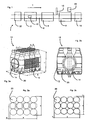
- Fig. 2a shows a representation of a container assembly 10. It can be seen that with the in Fig. 2a The example shown twelve containers 20 are combined in a container assembly.
- the reference number 20 denotes a single container.
- the reference numeral 12 relates to the film-like packaging means which is largely arranged around the containers.
- the reference symbols A, B and C identify the dimensions of the container assemblies. It would be possible here for the combination to be essentially cuboid, but due to the tapering mouth area of the containers, the container combinations are somewhat narrower at the upper end than at the lower end.
- the reference symbol H relates to the tolerances for the position of an imprint.
- the reference symbol 14 denotes an opening in the packaging means, which is also referred to as an eye, and the reference symbol G the tolerance for the central axis of this opening or the film eye.
- the reference symbols D and E identify shape tolerances for the offset.
- Figure 2b shows a side view of a container assembly, with the reference symbol G here representing a radius of the containers in the area of the closure.
- Fig. 3a; 3b show two examples of incorrectly compiled receptacles and incorrectly compiled receptacles.
- the middle row of containers (shown here by the dashed lines) is shifted by a distance D with respect to a target position.
- Such a combination of containers can cause problems when stacking one on top of the other.
- Figure 3b shows another example of an incorrect compilation. It can be seen here that the middle row is shifted laterally to the left in relation to the lower row, and that the individual longitudinal rows are shifted here by the amount F in the vertical direction. Such a combination of containers would also have to be classified as faulty and removed accordingly.
- FIG. 4 shows a roughly schematic representation of an inspection or testing device not according to the invention for a container assembly 10.
- This inspection device has an observation device 82, such as a camera, which is arranged above the container assemblies 10 or their transport path.
- Reference number 92 denotes lighting devices which in particular also illuminate the background of the container assembly 10 in order to achieve stronger contrasts and in particular to capture the contours of the container assembly 10, which are particularly relevant.
- Reference numeral 86 denotes a lens body which is in particular a Fresnel lens.
- This Fresnel lens preferably has a very short focal length and thus enables the observation device 82 to be arranged comparatively close to the container assembly.
- a telecentric observation of the container assembly 10 takes place by the observation device 82.
- a telecentric lens with a beam path that is telecentric on the object side. This would make it possible to capture objects, in this case the arrangement of containers, without any perspective distortion.
- a telecentric beam path on the image side could also be used, which serves in particular to parallelize the beam path. In this case, the exit pupil is at infinity, so that the cones of rays arrive essentially perpendicularly on the image plane.
- a bilateral telecentricity could also be used, that is to say the combination of an object-side and an image-side telecentric beam path.
- Telecentricity on the image sensor side is achieved in that the optical element is a Fresnel lens with a focal length of 600 mm.
- a groove spacing of less than 1 mm is preferred, particularly preferably ⁇ 0.5 mm.
- the distance to generate telecentricity is 550 mm to the lens, which can be a zoom with a focal length of 10-40mm. Lenses with a light intensity better than 1: 4, 1: 2.8 are preferred. In this way, a usable telecentric image field diameter of approx. 350mm is achieved:
- a distance between an upper side of the container assembly and the image recording device or an image recording element is advantageously between 5 cm and 250 cm, preferably between 10 cm and 150 cm, preferably between 30 cm and 120 cm, preferably between 40 cm and 120 cm.
- the lighting devices 92 are advantageously arranged here on the same side with respect to the container assemblies 10 as the observation device, ie here also above. In this way it can be avoided that light from the lighting devices 92 reaches the observation device 82 directly.
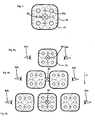
- Fig. 5 shows a further representation to illustrate the method. It can be seen that here the observation device 8 is arranged centrally above the container assembly 10 (at least at the time of the image recording).
- the reference symbol 20 again identifies the containers.
- the reference numeral 20a denotes an opening or closure area of the containers.
- the image recording device is attached above the container track, which is directed vertically downwards and in particular, triggered by a sensor, such as a light barrier, detects each container arrangement from above.
- a sensor such as a light barrier
- Figure 6b shows a further configuration in which two container assemblies are transported next to one another in the direction of the transport path T.
- an image recording device 82 is arranged between these two container assemblies and two further image recording devices 82a, 82b or corresponding mirror optics are each arranged on the two sides of the container assemblies.
- Figure 6c shows a representation in which three container assemblies are moved parallel or side by side in the transport direction T.
- an image pickup device 82 Arranged above the middle container assembly and two further image recording devices 82a, 82b on the two sides.
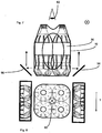
- Figures 7 and 8 show a further representation to illustrate the optical measurement.
- Radiation deflecting elements 96 or mirrors are provided here, which enable the entire side surfaces of the container assembly 10 to be mapped. As mentioned above, a complete image of the side surfaces can be put together from areas that are mapped piece by piece. It would also be possible to map the images of the side surfaces onto the image recording device 82. For this purpose, partially transparent mirrors could be used or multiple lighting with light of different wavelengths could be used.
- the container assemblies are transported here perpendicular to the plane of the figure. The opening of the packaging means shown here is not necessarily present.
- Fig. 8 shows such a representation, with the two reflection or mirror elements 96 each being able to capture the bottom areas of the container assemblies. Any distortions that may result from the optics can advantageously be corrected using suitable software. In this way, it would also be possible to include the respective side areas of the container assemblies, it also being possible for further mirror elements 96 (not shown) to be provided.
- FIGS. 9 and 10 show a further embodiment.
- an observation device 82 in the form of a line scanner 182 is used.
- This line scanner 182 is also arranged stationary here and the container assembly moves relative to this line scanner 182 along the transport path T.
- This line scanner can also compose a complete image from individual columns of the side view. It would also be possible that critical areas, such as the welding of the lower side film flap, can additionally or alternatively be checked for their quality with a capacitive sensor.
- Fig. 10 shows a corresponding view from above, two such line scanners 182 being used here.
- the Figures 11a, 11b show a representation for checking the bottom welding.
- an observation device 82 such as a capacitive sensor or a line scanner, can be used, which are arranged between two transport devices 6 and check the container during the transfer, for example, from the left transport device to the right transport device 6. It is possible here for the observation device to check the container assemblies 10 directly, but it would also be possible for the beam path, as in FIG Figure 11b shown, is guided over a deflection device such as a mirror.
- Fig. 12 illustrates a further observation of the container assemblies, in which case the two observation devices 82a and 82b in particular can also be used to project the end faces into the recording area of a camera. Two cameras are provided here, which observe the container track at an angle from above.
- Fig. 13 shows a representation of a possible image recording.
- the line L shown in the upper partial image can show the actually measured deviation from an ideal packaging dimension, for example from a side surface.
- the two lower lines can represent the corresponding deviations in the other two directions.
- limit values can be formed which are still considered to be acceptable. If these are exceeded, an information output device can inform the user that the container combination in question has been incorrectly packed and, for this reason, is to be ejected, for example.
- a downstream discharge device could discharge the container assembly in question. It would also be possible, as a function of such a result, to regulate a treatment unit lying in the transport direction of the container assembly 10 or to modify its operation. However, such a discharge advantageously takes place (fully) automatically.
- the Figures 14a-14c show three representations of the shrinking device 4.
- This shrinking device is designed here as a so-called shrink tunnel.
- the reference number 6 again relates to the transport device.
- the observation device 8 is provided directly following the shrink device.
- Figure 14b shows a further embodiment of the shrinking device 4.
- the reference numerals 24 and 28 relate to laterally arranged application devices which apply hot air to the container assembly from the side. Between the transport tracks of the container assemblies 10 there is a further actuation device 32 which enables both container assemblies to be applied from both sides. By means of a further application device 26, hot air is also applied to the container assemblies from below.
- a distance between the lateral loading devices 24, 28 and 32 is preferably adjustable or changeable. It would also be conceivable that a height level of the individual loading devices 24, 28 and 32 with respect to the transport device or the loading device 26 can be changed.
- Figure 14c shows a further illustration of a shrinking device 4.
- three application devices 24, 28 and 26 are provided which apply hot air to the container assemblies 10 with the packaging means arranged thereon from the sides and from below.
Landscapes
- Engineering & Computer Science (AREA)
- Mechanical Engineering (AREA)
- Physics & Mathematics (AREA)
- Health & Medical Sciences (AREA)
- Life Sciences & Earth Sciences (AREA)
- Chemical & Material Sciences (AREA)
- Analytical Chemistry (AREA)
- Biochemistry (AREA)
- General Health & Medical Sciences (AREA)
- General Physics & Mathematics (AREA)
- Immunology (AREA)
- Pathology (AREA)
- Investigating Materials By The Use Of Optical Means Adapted For Particular Applications (AREA)
- Length Measuring Devices By Optical Means (AREA)
Claims (4)
- Dispositif (1) de fabrication d'assemblages de récipients (10), le dispositif comprenant un système d'emballage (2), lequel est configuré pour envelopper plusieurs récipients (20) au moins partiellement d'un emballage (12) du type film et pour ainsi former un assemblage de récipients (10), ledit dispositif comprenant un système de rétraction (4), lequel est configuré pour rétracter l'emballage (12) enveloppant au moins partiellement les récipients (20), un système de transport (6), lequel est configuré pour transporter les récipients (20) enveloppés de l'emballage (12) dans une direction de transport prédéfinie et un système d'inspection (8), lequel est configuré pour inspecter les récipients (20) enveloppés au moins partiellement de l'emballage (12) après le processus de rétraction, ce système d'inspection (8) étant orienté vers une zone du dispositif (1) qui est située en aval du système de rétraction (4), le système d'inspection (8) étant agencé dans la direction de transport (R) des récipients (20) en aval du système de rétraction (4), et le système d'inspection (8) étant configuré pour détecter une position relative au moins d'un récipient (20) de l'assemblage de récipients (10) par rapport à au moins un autre récipient (20) de cet assemblage de récipients (10), et une unité d'évaluation étant également prévue, laquelle est configurée pour évaluer ces positions détectées.
- Dispositif (1) selon la revendication 1,
caractérisé en ce que
le système d'inspection (8) comprend un système de capture d'images (82), lequel est adapté et conçu pour capturer des images de l'assemblage de récipients (10). - Dispositif (1) selon au moins l'une des revendications précédentes,
caractérisé en ce que
le dispositif (1) comprend un système de détection de position (16), lequel détecte une position des récipientsenveloppés de l'emballage dans la direction de transport. - Procédé de production d'assemblages de récipients au moyen d'un dispositif selon la revendication 1 comprenant les étapes consistant à :- former un assemblage de récipients à partir de plusieurs récipients (20);- appliquer un emballage du type film sur les récipients (20), cet emballage du type film (12) entourant au moins en sections l'assemblage des récipients (20) ;- rétracter l'emballage (12) du type film sur les récipients (20) ;- inspecter les récipients (20) sur lesquels est placé l'emballage après la rétraction de l'emballage (12), le système d'inspection (8) étant orienté vers une zone du dispositif (1) qui est située en aval du système de rétraction (4), et au moins une position relative d'un premier récipient (20) de l'assemblage de récipients (10) par rapport à un deuxième récipient de l'assemblage de récipients (10) étant détectée, et l'unité d'évaluation évaluant ces positions détectées.
Applications Claiming Priority (1)
| Application Number | Priority Date | Filing Date | Title |
|---|---|---|---|
| DE102013104666.5A DE102013104666A1 (de) | 2013-05-07 | 2013-05-07 | Vorrichtung und Verfahren zum Herstellen von Behältniszusammenstellungen |
Publications (3)
| Publication Number | Publication Date |
|---|---|
| EP2801533A1 EP2801533A1 (fr) | 2014-11-12 |
| EP2801533B1 EP2801533B1 (fr) | 2016-12-28 |
| EP2801533B2 true EP2801533B2 (fr) | 2021-04-07 |
Family
ID=50679907
Family Applications (1)
| Application Number | Title | Priority Date | Filing Date |
|---|---|---|---|
| EP14167404.4A Active EP2801533B2 (fr) | 2013-05-07 | 2014-05-07 | Dispositif et procédé de fabrication d'assemblages de récipient |
Country Status (5)
| Country | Link |
|---|---|
| US (1) | US20140331617A1 (fr) |
| EP (1) | EP2801533B2 (fr) |
| CN (1) | CN104139894B (fr) |
| DE (1) | DE102013104666A1 (fr) |
| ES (1) | ES2619609T3 (fr) |
Families Citing this family (17)
| Publication number | Priority date | Publication date | Assignee | Title |
|---|---|---|---|---|
| DE102013104417A1 (de) * | 2013-04-30 | 2014-10-30 | Krones Aktiengesellschaft | Verfahren zum Überführen eines Schrumpftunnels in einen Produktionsmodus und Verfahren zum Überführen eines Schrumpftunnels von einem Produktionsmodus in einen Stillstand- Modus |
| BR112017017361A2 (pt) * | 2015-02-27 | 2018-04-10 | Dow Global Technologies Llc | métodos e sistemas para medir as forças de uma película retrátil |
| CA3012732C (fr) | 2016-01-26 | 2023-01-03 | Symbotic Canada, Ulc | Systeme et procede d'inspection de marchandises encaissees |
| DE102016203435A1 (de) * | 2016-03-02 | 2017-09-07 | Krones Aktiengesellschaft | Abschnitt einer Verpackungslinie für Getränkebehältnisse und Verfahren zum Umgang mit Getränkebehältnissen während ihres Transportes entlang einer Verpackungslinie |
| DE102016211619A1 (de) * | 2016-06-28 | 2017-12-28 | Krones Ag | Anlage zum Behandeln von Behältern, sowie Verfahren zum Verpacken von gefüllten Behältern |
| EP4197531B1 (fr) * | 2016-10-12 | 2024-08-14 | Boveda Inc. | Emballage de produit comprenant un dispositif de régulation de l'humidité de l'espace de tête |
| DE102018107369A1 (de) * | 2018-03-28 | 2019-10-02 | Krones Ag | Verfahren zum korrekten Einsortieren eines Behälterbatch |
| US11661225B2 (en) * | 2018-10-10 | 2023-05-30 | Illinois Tool Works Inc. | Center divider for shrink oven |
| DE102018127823A1 (de) * | 2018-11-07 | 2020-05-07 | Krones Aktiengesellschaft | Verfahren und System zum Verpacken von Artikeln |
| DE102019202008A1 (de) * | 2019-02-14 | 2020-08-20 | Krones Aktiengesellschaft | Verfahren zum Steuern und/oder Regeln eines Schrumpftunnels und Vorrichtung zum Aufschrumpfen thermoplastischen Verpackungsmaterials auf Artikel |
| DE102019106530A1 (de) * | 2019-03-14 | 2020-09-17 | Krones Aktiengesellschaft | Schrumpfvorrichtung und Verfahren zum Einstellen und/oder Verstellen und/oder Anpassen einer Schrumpfvorrichtung |
| DE102019206389A1 (de) * | 2019-05-03 | 2020-11-05 | Multivac Sepp Haggenmüller Se & Co. Kg | Verfahren zur erkennung von werkzeugfehlstellung und verpackungsmaschine |
| DE102020207933A1 (de) * | 2020-06-26 | 2021-12-30 | Krones Aktiengesellschaft | Schrumpfvorrichtung, Verpackungsanlage und Verfahren zur Herstellung von Verpackungseinheiten |
| DE102020120820A1 (de) * | 2020-08-06 | 2022-02-10 | Krones Aktiengesellschaft | Verfahren und Verpackungsvorrichtung zum Herstellen von Schrumpfgebinden |
| US12129160B2 (en) * | 2022-02-02 | 2024-10-29 | Stephen Michael Brown | Method for dispensing customized hemp extract tinctures |
| DE102022122553A1 (de) * | 2022-09-06 | 2024-03-07 | Krones Aktiengesellschaft | Verfahren zur Steuerung einer Verpackungsanlage und Verpackungsanlage |
| DE102024131911A1 (de) * | 2024-10-31 | 2026-04-30 | Syntegon Technology Gmbh | System zur Erkennung eines Verpackungselements |
Citations (3)
| Publication number | Priority date | Publication date | Assignee | Title |
|---|---|---|---|---|
| EP0330495A2 (fr) † | 1988-02-26 | 1989-08-30 | R.J. Reynolds Tobacco Company | Système d'inspection d'emballages |
| DE102007014802A1 (de) † | 2007-03-28 | 2008-10-09 | Khs Ag | Verfahren zur Überwachung, Steuerung und Optimierung von Abfüllanlagen für Lebensmittel, insbesondere für Getränkeflaschen |
| US20090293430A1 (en) † | 2008-05-30 | 2009-12-03 | Iocco Jeffrey R | Method for positioning a loaded bag in a vacuum chamber |
Family Cites Families (48)
| Publication number | Priority date | Publication date | Assignee | Title |
|---|---|---|---|---|
| US3889447A (en) * | 1973-05-24 | 1975-06-17 | Smithkline Corp | Quality control monitor for medicinal capsule packaging apparatus |
| US4365456A (en) * | 1976-05-05 | 1982-12-28 | The Mead Corporation | Method of and apparatus for packaging |
| JPS5546172A (en) * | 1978-09-29 | 1980-03-31 | Kirin Brewery Co Ltd | Detector for foreign material |
| US4266674A (en) * | 1979-02-07 | 1981-05-12 | Richard Equipment Company, Inc. | Optoelectronic device for automatically inspecting a group of cigarettes or the like |
| IT1145039B (it) * | 1981-03-06 | 1986-11-05 | Gd Spa | Dispositivo di trasferimento e controllo di gruppi di sigarette |
| US4514955A (en) * | 1981-04-06 | 1985-05-07 | Lantech, Inc. | Feedback controlled stretch wrapping apparatus and process |
| US4809342A (en) * | 1984-11-27 | 1989-02-28 | Kappner Helmut A | Process and arrangements for the indentification marking and recognition of objects |
| US4689934A (en) * | 1985-03-08 | 1987-09-01 | The Mead Packaging Corporation | Apparatus for and method of applying wrap to article clusters |
| US5088269A (en) * | 1990-11-26 | 1992-02-18 | Nigrelli Systems, Inc. | Process and apparatus for producing a sanitary carrier for a plurality of containers |
| DE4112263A1 (de) * | 1991-04-15 | 1992-10-22 | Focke & Co | Verfahren und vorrichtung zum elektro-optischen abtasten von (zigaretten-)packungen |
| DE4114798A1 (de) * | 1991-05-07 | 1992-11-12 | Bosch Gmbh Robert | Vorrichtung zum sterilisieren von temperaturbelastbaren verpackungsbehaeltern |
| US5235649A (en) * | 1991-06-13 | 1993-08-10 | Videk Corporation | Cigarette inspection method |
| US6330351B1 (en) * | 1996-11-29 | 2001-12-11 | Kabushiki Kaisha Yuyama Seisakusho | Drug inspection device and drug packaging device |
| GB9719522D0 (en) * | 1997-09-12 | 1997-11-19 | Newman Paul B D | Automated packaging |
| US6049379A (en) * | 1997-12-30 | 2000-04-11 | Coors Brewing Company | Method for inspecting translucent objects using imaging techniques |
| EP0941775B1 (fr) * | 1998-03-02 | 2005-10-26 | Focke & Co. (GmbH & Co. KG) | Méthode et dispositif pour examiner optiquement des paquets |
| US6324253B1 (en) * | 1998-08-26 | 2001-11-27 | Yuyama Mfg. Co., Ltd. | Tablet inspection apparatus |
| US6523328B1 (en) * | 1999-09-13 | 2003-02-25 | Gilbert L. De Cardenas | System and apparatus for an automated container filling production line |
| JP3558974B2 (ja) * | 2000-08-30 | 2004-08-25 | ローレル精機株式会社 | 硬貨包装機 |
| US20020148203A1 (en) * | 2001-04-12 | 2002-10-17 | Waddell, David Landon | Method and apparatus for packaging flexible containers |
| JP3926149B2 (ja) * | 2001-12-25 | 2007-06-06 | 富士フイルム株式会社 | ロール状物の自動包装方法およびシステム |
| ITBO20020529A1 (it) * | 2002-08-08 | 2004-02-09 | Gd Spa | Metodo per il controllo di materiale di incarto in |
| DE10315116A1 (de) * | 2003-04-03 | 2004-10-14 | Khs Maschinen- Und Anlagenbau Ag | Vorrichtung für das Anbringen von Tragegriffen |
| US20040231481A1 (en) * | 2003-05-23 | 2004-11-25 | Floding Daniel Leonard | Apparatus for perforating or slitting heat shrink film |
| NL1025161C1 (nl) * | 2003-08-19 | 2005-07-04 | Global Factories B V | Werkwijze en inrichting voor het spreiden van/naast op elkaar liggende voorwerpen. |
| DE102004032528C5 (de) * | 2004-07-06 | 2012-04-05 | Khs Gmbh | Verfahren zum Durchführen eines Rollenwechsels bei einer Versorgungseinheit zum Zuführen eines bahnartigen Flachmaterials an eine Verpackungsmaschine oder dergleichen Verarbeitungsmaschine sowie Versorgungseinheit zum Durchführen dieses Verfahrens |
| US9238518B2 (en) * | 2004-10-01 | 2016-01-19 | Edge Medical Properties, Llc | Inspection system and method with a control process that inspects different medications |
| JP4261465B2 (ja) * | 2004-11-16 | 2009-04-30 | ニッカウヰスキー株式会社 | シュリンクフィルム及び物品、並びに、それらに関連する処理装置、検査方法及び製造方法、 |
| DE102005017957A1 (de) * | 2005-04-18 | 2006-10-26 | Khs Ag | Inspektionsvorrichtung |
| KR100650285B1 (ko) * | 2005-05-25 | 2006-11-27 | (주)제이브이엠 | 약포 검사시스템 |
| DE102005031794A1 (de) * | 2005-07-07 | 2007-01-25 | Khs Ag | Verfahren und Vorrichtung zum Überprüfen einer Behälterbehandlungsanlage |
| US7881818B2 (en) * | 2005-10-07 | 2011-02-01 | Esko Ip Nv | Flexible packaging incorporating two-dimensional graphics |
| DE102005050902A1 (de) * | 2005-10-21 | 2007-05-03 | Khs Ag | Vorrichtung zum Ausrichten von Behältern sowie Etikettiermaschine mit einer solchen Vorrichtung |
| EP1957371B1 (fr) * | 2005-12-09 | 2009-05-06 | Khs Ag | Procede de retraction pour produire des emballages solides transportables et imprimables et dispositif permettant de mettre en oeuvre ce procede |
| DE102006003338A1 (de) * | 2006-01-23 | 2007-07-26 | Khs Ag | Gebinde sowie Verfahren und Vorrichtung zum Herstellen eines Gebindes |
| ITFI20060152A1 (it) * | 2006-06-16 | 2007-12-17 | Kpl Packaging Spa | Macchina e metodo perli confezionamento di gruppi di prodotti |
| EP2064536A4 (fr) * | 2006-08-28 | 2012-05-30 | Detection Systems Pty Ltd | Appareil et procédé de détection pour une chaîne de production |
| EP2084068A1 (fr) * | 2006-09-19 | 2009-08-05 | MeadWestvaco Packaging Systems LLC | Dispositif d'alignement d'article |
| US7916927B2 (en) * | 2007-01-16 | 2011-03-29 | Asml Netherlands B.V. | Inspection method and apparatus, lithographic apparatus, lithographic processing cell and device manufacturing method |
| DE102007011526A1 (de) * | 2007-03-09 | 2008-09-11 | Khs Ag | Schrumpftunnel |
| DE102009025912A1 (de) * | 2009-06-03 | 2010-12-09 | Krones Ag | Körper und aus Körpern erstellte Gebinde sowie Vorrichtung und Verfahren zur Erstellung von Gebinden |
| US8311313B1 (en) * | 2010-02-08 | 2012-11-13 | Surescan Corporation | Imaging inspection apparatus incorporating a device for solving cubic polynomials |
| ITMI20100410A1 (it) * | 2010-03-12 | 2011-09-13 | Ronchi Mario Spa | Stazione di alimentazione e sistema di alimentazione e trattamento di flaconi comprendente tale stazione |
| WO2012005004A1 (fr) * | 2010-07-09 | 2012-01-12 | パナソニック株式会社 | Procédé et système d'assistance à l'inspection de comprimés |
| US10112735B2 (en) * | 2010-10-21 | 2018-10-30 | Siemens Industry, Inc. | Package unbundling system |
| GB2485390A (en) * | 2010-11-12 | 2012-05-16 | Sony Corp | Video Surveillance System that Detects Changes by Comparing a Current Image with a Reference Image |
| US20130120557A1 (en) * | 2011-11-14 | 2013-05-16 | Microscan Systems, Inc. | Part inspection system |
| DE102012102221A1 (de) * | 2012-03-16 | 2013-09-19 | Krones Ag | Vorrichtung zur verwendung bei einer inspektion eines behälters, inspektionssystem und inspektionsverfahren |
-
2013
- 2013-05-07 DE DE102013104666.5A patent/DE102013104666A1/de not_active Withdrawn
-
2014
- 2014-04-22 US US14/258,565 patent/US20140331617A1/en not_active Abandoned
- 2014-05-04 CN CN201410185150.4A patent/CN104139894B/zh active Active
- 2014-05-07 ES ES14167404.4T patent/ES2619609T3/es active Active
- 2014-05-07 EP EP14167404.4A patent/EP2801533B2/fr active Active
Patent Citations (3)
| Publication number | Priority date | Publication date | Assignee | Title |
|---|---|---|---|---|
| EP0330495A2 (fr) † | 1988-02-26 | 1989-08-30 | R.J. Reynolds Tobacco Company | Système d'inspection d'emballages |
| DE102007014802A1 (de) † | 2007-03-28 | 2008-10-09 | Khs Ag | Verfahren zur Überwachung, Steuerung und Optimierung von Abfüllanlagen für Lebensmittel, insbesondere für Getränkeflaschen |
| US20090293430A1 (en) † | 2008-05-30 | 2009-12-03 | Iocco Jeffrey R | Method for positioning a loaded bag in a vacuum chamber |
Also Published As
| Publication number | Publication date |
|---|---|
| CN104139894B (zh) | 2017-05-10 |
| ES2619609T3 (es) | 2017-06-26 |
| DE102013104666A1 (de) | 2014-11-13 |
| CN104139894A (zh) | 2014-11-12 |
| US20140331617A1 (en) | 2014-11-13 |
| EP2801533A1 (fr) | 2014-11-12 |
| EP2801533B1 (fr) | 2016-12-28 |
Similar Documents
| Publication | Publication Date | Title |
|---|---|---|
| EP2801533B2 (fr) | Dispositif et procédé de fabrication d'assemblages de récipient | |
| EP3122638B1 (fr) | Machine de production et/ou d'emballage de produit de l'industrie du tabac | |
| EP1036003B1 (fr) | Procede pour verifier que des groupes de cigarettes sont complets et que celles-ci sont suffisamment remplies | |
| EP3298391B1 (fr) | Procédé de contrôle et système de contrôle | |
| DE68926830T2 (de) | Verfahren und Vorrichtung zur Prüfung der Seitenwand einer Flasche | |
| EP0682991A2 (fr) | Machine automatique pour le tri, respectivement la classification d'après la forme et la couleur, de petits produits de l'industrie pharmaceutique et des friandises | |
| DE102008062370A1 (de) | Verfahren und Vorrichtung zur Prüfung von bei der Herstellung und/oder Verpackung von Zigaretten zu prüfenden Objekten | |
| EP3504538A1 (fr) | Système d'inspection optique pour préformes | |
| DE10065290C2 (de) | Verfahren und Vorrichtung zur optischen Inspektion von Flaschen | |
| EP3541727A1 (fr) | Procédé et dispositif de détection de perturbations lors d'un transport d'objets | |
| DE69705532T2 (de) | Verfahren zur überprüfung von textilspulen und vorrichtung für seine durchführung | |
| DE102013105214A1 (de) | Untersuchungsverfahren eines Produkts in einer Verpackungsmaschine | |
| EP4033227A1 (fr) | Procédé de détection optique de défauts des articles en céramique | |
| WO2021110308A1 (fr) | Procédé de contrôle d'une épaisseur de paroi d'un récipient constitué d'un matériau au moins partiellement transparent | |
| EP3110701B1 (fr) | Dispositif d'inspection de recipients | |
| DE102021109286A1 (de) | Verfahren und Vorrichtung zum Inspizieren von Behältnissen mit Feststellung einer Drehstellung eines Behältnisverschlusses | |
| EP4106557B1 (fr) | Procédé et dispositif d'examen de produits en forme de tige de l'industrie des cigarettes | |
| EP2671649B1 (fr) | Dispositif d'identification d'une bouteille | |
| WO2007134632A1 (fr) | Procédé de détection d'irrégularités sur un objet à mesurer | |
| DE102010004972A1 (de) | Vorrichtung und Verfahren zum Inspizieren von Behältnissen | |
| EP3465172A1 (fr) | Dispositif et procédé d'inspection de contenants | |
| CH716479A1 (de) | Verfahren und Vorrichtung zur optischen Prüfung von Hohlkörpern. | |
| DE102013105216A1 (de) | Untersuchungsverfahren eines Produkts in einer Verpackungsmaschine | |
| DE202007000471U1 (de) | Verpackungsmaschine zur Erfassung von Unregelmäßigkeiten an einem Messobjekt | |
| EP4276450A1 (fr) | Dispositif et procédé d'inspection de récipients avec détection de position |
Legal Events
| Date | Code | Title | Description |
|---|---|---|---|
| PUAI | Public reference made under article 153(3) epc to a published international application that has entered the european phase |
Free format text: ORIGINAL CODE: 0009012 |
|
| 17P | Request for examination filed |
Effective date: 20140507 |
|
| AK | Designated contracting states |
Kind code of ref document: A1 Designated state(s): AL AT BE BG CH CY CZ DE DK EE ES FI FR GB GR HR HU IE IS IT LI LT LU LV MC MK MT NL NO PL PT RO RS SE SI SK SM TR |
|
| AX | Request for extension of the european patent |
Extension state: BA ME |
|
| R17P | Request for examination filed (corrected) |
Effective date: 20150512 |
|
| RBV | Designated contracting states (corrected) |
Designated state(s): AL AT BE BG CH CY CZ DE DK EE ES FI FR GB GR HR HU IE IS IT LI LT LU LV MC MK MT NL NO PL PT RO RS SE SI SK SM TR |
|
| 17Q | First examination report despatched |
Effective date: 20150917 |
|
| GRAP | Despatch of communication of intention to grant a patent |
Free format text: ORIGINAL CODE: EPIDOSNIGR1 |
|
| RIC1 | Information provided on ipc code assigned before grant |
Ipc: B65B 57/00 20060101ALI20160304BHEP Ipc: B65B 53/06 20060101AFI20160304BHEP Ipc: G06T 7/00 20060101ALI20160304BHEP Ipc: G01N 21/88 20060101ALI20160304BHEP Ipc: G01N 21/95 20060101ALI20160304BHEP |
|
| INTG | Intention to grant announced |
Effective date: 20160412 |
|
| GRAJ | Information related to disapproval of communication of intention to grant by the applicant or resumption of examination proceedings by the epo deleted |
Free format text: ORIGINAL CODE: EPIDOSDIGR1 |
|
| GRAS | Grant fee paid |
Free format text: ORIGINAL CODE: EPIDOSNIGR3 |
|
| GRAP | Despatch of communication of intention to grant a patent |
Free format text: ORIGINAL CODE: EPIDOSNIGR1 |
|
| INTC | Intention to grant announced (deleted) | ||
| INTG | Intention to grant announced |
Effective date: 20160826 |
|
| STAA | Information on the status of an ep patent application or granted ep patent |
Free format text: STATUS: GRANT OF PATENT IS INTENDED |
|
| GRAA | (expected) grant |
Free format text: ORIGINAL CODE: 0009210 |
|
| STAA | Information on the status of an ep patent application or granted ep patent |
Free format text: STATUS: THE PATENT HAS BEEN GRANTED |
|
| AK | Designated contracting states |
Kind code of ref document: B1 Designated state(s): AL AT BE BG CH CY CZ DE DK EE ES FI FR GB GR HR HU IE IS IT LI LT LU LV MC MK MT NL NO PL PT RO RS SE SI SK SM TR |
|
| REG | Reference to a national code |
Ref country code: GB Ref legal event code: FG4D Free format text: NOT ENGLISH |
|
| REG | Reference to a national code |
Ref country code: CH Ref legal event code: EP |
|
| REG | Reference to a national code |
Ref country code: AT Ref legal event code: REF Ref document number: 857035 Country of ref document: AT Kind code of ref document: T Effective date: 20170115 |
|
| REG | Reference to a national code |
Ref country code: IE Ref legal event code: FG4D Free format text: LANGUAGE OF EP DOCUMENT: GERMAN |
|
| REG | Reference to a national code |
Ref country code: DE Ref legal event code: R096 Ref document number: 502014002301 Country of ref document: DE |
|
| PG25 | Lapsed in a contracting state [announced via postgrant information from national office to epo] |
Ref country code: LV Free format text: LAPSE BECAUSE OF FAILURE TO SUBMIT A TRANSLATION OF THE DESCRIPTION OR TO PAY THE FEE WITHIN THE PRESCRIBED TIME-LIMIT Effective date: 20161228 |
|
| REG | Reference to a national code |
Ref country code: FR Ref legal event code: PLFP Year of fee payment: 4 |
|
| REG | Reference to a national code |
Ref country code: LT Ref legal event code: MG4D |
|
| PG25 | Lapsed in a contracting state [announced via postgrant information from national office to epo] |
Ref country code: NO Free format text: LAPSE BECAUSE OF FAILURE TO SUBMIT A TRANSLATION OF THE DESCRIPTION OR TO PAY THE FEE WITHIN THE PRESCRIBED TIME-LIMIT Effective date: 20170328 Ref country code: LT Free format text: LAPSE BECAUSE OF FAILURE TO SUBMIT A TRANSLATION OF THE DESCRIPTION OR TO PAY THE FEE WITHIN THE PRESCRIBED TIME-LIMIT Effective date: 20161228 Ref country code: GR Free format text: LAPSE BECAUSE OF FAILURE TO SUBMIT A TRANSLATION OF THE DESCRIPTION OR TO PAY THE FEE WITHIN THE PRESCRIBED TIME-LIMIT Effective date: 20170329 Ref country code: SE Free format text: LAPSE BECAUSE OF FAILURE TO SUBMIT A TRANSLATION OF THE DESCRIPTION OR TO PAY THE FEE WITHIN THE PRESCRIBED TIME-LIMIT Effective date: 20161228 |
|
| REG | Reference to a national code |
Ref country code: NL Ref legal event code: MP Effective date: 20161228 |
|
| PG25 | Lapsed in a contracting state [announced via postgrant information from national office to epo] |
Ref country code: FI Free format text: LAPSE BECAUSE OF FAILURE TO SUBMIT A TRANSLATION OF THE DESCRIPTION OR TO PAY THE FEE WITHIN THE PRESCRIBED TIME-LIMIT Effective date: 20161228 Ref country code: RS Free format text: LAPSE BECAUSE OF FAILURE TO SUBMIT A TRANSLATION OF THE DESCRIPTION OR TO PAY THE FEE WITHIN THE PRESCRIBED TIME-LIMIT Effective date: 20161228 Ref country code: HR Free format text: LAPSE BECAUSE OF FAILURE TO SUBMIT A TRANSLATION OF THE DESCRIPTION OR TO PAY THE FEE WITHIN THE PRESCRIBED TIME-LIMIT Effective date: 20161228 |
|
| REG | Reference to a national code |
Ref country code: ES Ref legal event code: FG2A Ref document number: 2619609 Country of ref document: ES Kind code of ref document: T3 Effective date: 20170626 |
|
| PG25 | Lapsed in a contracting state [announced via postgrant information from national office to epo] |
Ref country code: NL Free format text: LAPSE BECAUSE OF FAILURE TO SUBMIT A TRANSLATION OF THE DESCRIPTION OR TO PAY THE FEE WITHIN THE PRESCRIBED TIME-LIMIT Effective date: 20161228 |
|
| PG25 | Lapsed in a contracting state [announced via postgrant information from national office to epo] |
Ref country code: RO Free format text: LAPSE BECAUSE OF FAILURE TO SUBMIT A TRANSLATION OF THE DESCRIPTION OR TO PAY THE FEE WITHIN THE PRESCRIBED TIME-LIMIT Effective date: 20161228 Ref country code: IS Free format text: LAPSE BECAUSE OF FAILURE TO SUBMIT A TRANSLATION OF THE DESCRIPTION OR TO PAY THE FEE WITHIN THE PRESCRIBED TIME-LIMIT Effective date: 20170428 Ref country code: CZ Free format text: LAPSE BECAUSE OF FAILURE TO SUBMIT A TRANSLATION OF THE DESCRIPTION OR TO PAY THE FEE WITHIN THE PRESCRIBED TIME-LIMIT Effective date: 20161228 Ref country code: EE Free format text: LAPSE BECAUSE OF FAILURE TO SUBMIT A TRANSLATION OF THE DESCRIPTION OR TO PAY THE FEE WITHIN THE PRESCRIBED TIME-LIMIT Effective date: 20161228 Ref country code: SK Free format text: LAPSE BECAUSE OF FAILURE TO SUBMIT A TRANSLATION OF THE DESCRIPTION OR TO PAY THE FEE WITHIN THE PRESCRIBED TIME-LIMIT Effective date: 20161228 |
|
| PG25 | Lapsed in a contracting state [announced via postgrant information from national office to epo] |
Ref country code: BG Free format text: LAPSE BECAUSE OF FAILURE TO SUBMIT A TRANSLATION OF THE DESCRIPTION OR TO PAY THE FEE WITHIN THE PRESCRIBED TIME-LIMIT Effective date: 20170328 Ref country code: PL Free format text: LAPSE BECAUSE OF FAILURE TO SUBMIT A TRANSLATION OF THE DESCRIPTION OR TO PAY THE FEE WITHIN THE PRESCRIBED TIME-LIMIT Effective date: 20161228 Ref country code: SM Free format text: LAPSE BECAUSE OF FAILURE TO SUBMIT A TRANSLATION OF THE DESCRIPTION OR TO PAY THE FEE WITHIN THE PRESCRIBED TIME-LIMIT Effective date: 20161228 Ref country code: PT Free format text: LAPSE BECAUSE OF FAILURE TO SUBMIT A TRANSLATION OF THE DESCRIPTION OR TO PAY THE FEE WITHIN THE PRESCRIBED TIME-LIMIT Effective date: 20170428 Ref country code: LU Free format text: LAPSE BECAUSE OF NON-PAYMENT OF DUE FEES Effective date: 20170531 |
|
| REG | Reference to a national code |
Ref country code: DE Ref legal event code: R026 Ref document number: 502014002301 Country of ref document: DE |
|
| PLBI | Opposition filed |
Free format text: ORIGINAL CODE: 0009260 |
|
| 26 | Opposition filed |
Opponent name: KHS GMBH Effective date: 20170926 |
|
| PLAX | Notice of opposition and request to file observation + time limit sent |
Free format text: ORIGINAL CODE: EPIDOSNOBS2 |
|
| PG25 | Lapsed in a contracting state [announced via postgrant information from national office to epo] |
Ref country code: DK Free format text: LAPSE BECAUSE OF FAILURE TO SUBMIT A TRANSLATION OF THE DESCRIPTION OR TO PAY THE FEE WITHIN THE PRESCRIBED TIME-LIMIT Effective date: 20161228 |
|
| REG | Reference to a national code |
Ref country code: CH Ref legal event code: PL |
|
| PG25 | Lapsed in a contracting state [announced via postgrant information from national office to epo] |
Ref country code: MC Free format text: LAPSE BECAUSE OF FAILURE TO SUBMIT A TRANSLATION OF THE DESCRIPTION OR TO PAY THE FEE WITHIN THE PRESCRIBED TIME-LIMIT Effective date: 20161228 |
|
| REG | Reference to a national code |
Ref country code: IE Ref legal event code: MM4A |
|
| PG25 | Lapsed in a contracting state [announced via postgrant information from national office to epo] |
Ref country code: LI Free format text: LAPSE BECAUSE OF NON-PAYMENT OF DUE FEES Effective date: 20170531 Ref country code: CH Free format text: LAPSE BECAUSE OF NON-PAYMENT OF DUE FEES Effective date: 20170531 Ref country code: SI Free format text: LAPSE BECAUSE OF FAILURE TO SUBMIT A TRANSLATION OF THE DESCRIPTION OR TO PAY THE FEE WITHIN THE PRESCRIBED TIME-LIMIT Effective date: 20161228 |
|
| PLBB | Reply of patent proprietor to notice(s) of opposition received |
Free format text: ORIGINAL CODE: EPIDOSNOBS3 |
|
| PG25 | Lapsed in a contracting state [announced via postgrant information from national office to epo] |
Ref country code: LU Free format text: LAPSE BECAUSE OF NON-PAYMENT OF DUE FEES Effective date: 20170507 |
|
| REG | Reference to a national code |
Ref country code: FR Ref legal event code: PLFP Year of fee payment: 5 |
|
| REG | Reference to a national code |
Ref country code: BE Ref legal event code: MM Effective date: 20170531 |
|
| PG25 | Lapsed in a contracting state [announced via postgrant information from national office to epo] |
Ref country code: IE Free format text: LAPSE BECAUSE OF NON-PAYMENT OF DUE FEES Effective date: 20170507 |
|
| PG25 | Lapsed in a contracting state [announced via postgrant information from national office to epo] |
Ref country code: BE Free format text: LAPSE BECAUSE OF NON-PAYMENT OF DUE FEES Effective date: 20170531 |
|
| PG25 | Lapsed in a contracting state [announced via postgrant information from national office to epo] |
Ref country code: MT Free format text: LAPSE BECAUSE OF FAILURE TO SUBMIT A TRANSLATION OF THE DESCRIPTION OR TO PAY THE FEE WITHIN THE PRESCRIBED TIME-LIMIT Effective date: 20161228 |
|
| PG25 | Lapsed in a contracting state [announced via postgrant information from national office to epo] |
Ref country code: HU Free format text: LAPSE BECAUSE OF FAILURE TO SUBMIT A TRANSLATION OF THE DESCRIPTION OR TO PAY THE FEE WITHIN THE PRESCRIBED TIME-LIMIT; INVALID AB INITIO Effective date: 20140507 |
|
| PGFP | Annual fee paid to national office [announced via postgrant information from national office to epo] |
Ref country code: PL Payment date: 20190529 Year of fee payment: 6 |
|
| APBM | Appeal reference recorded |
Free format text: ORIGINAL CODE: EPIDOSNREFNO |
|
| APBP | Date of receipt of notice of appeal recorded |
Free format text: ORIGINAL CODE: EPIDOSNNOA2O |
|
| APAH | Appeal reference modified |
Free format text: ORIGINAL CODE: EPIDOSCREFNO |
|
| PG25 | Lapsed in a contracting state [announced via postgrant information from national office to epo] |
Ref country code: CY Free format text: LAPSE BECAUSE OF FAILURE TO SUBMIT A TRANSLATION OF THE DESCRIPTION OR TO PAY THE FEE WITHIN THE PRESCRIBED TIME-LIMIT Effective date: 20161228 |
|
| PGFP | Annual fee paid to national office [announced via postgrant information from national office to epo] |
Ref country code: GB Payment date: 20190501 Year of fee payment: 6 |
|
| APBQ | Date of receipt of statement of grounds of appeal recorded |
Free format text: ORIGINAL CODE: EPIDOSNNOA3O |
|
| PG25 | Lapsed in a contracting state [announced via postgrant information from national office to epo] |
Ref country code: MK Free format text: LAPSE BECAUSE OF FAILURE TO SUBMIT A TRANSLATION OF THE DESCRIPTION OR TO PAY THE FEE WITHIN THE PRESCRIBED TIME-LIMIT Effective date: 20161228 |
|
| PG25 | Lapsed in a contracting state [announced via postgrant information from national office to epo] |
Ref country code: TR Free format text: LAPSE BECAUSE OF FAILURE TO SUBMIT A TRANSLATION OF THE DESCRIPTION OR TO PAY THE FEE WITHIN THE PRESCRIBED TIME-LIMIT Effective date: 20161228 |
|
| PG25 | Lapsed in a contracting state [announced via postgrant information from national office to epo] |
Ref country code: AL Free format text: LAPSE BECAUSE OF FAILURE TO SUBMIT A TRANSLATION OF THE DESCRIPTION OR TO PAY THE FEE WITHIN THE PRESCRIBED TIME-LIMIT Effective date: 20161228 |
|
| REG | Reference to a national code |
Ref country code: AT Ref legal event code: MM01 Ref document number: 857035 Country of ref document: AT Kind code of ref document: T Effective date: 20190507 |
|
| PG25 | Lapsed in a contracting state [announced via postgrant information from national office to epo] |
Ref country code: AT Free format text: LAPSE BECAUSE OF NON-PAYMENT OF DUE FEES Effective date: 20190507 |
|
| APBY | Invitation to file observations in appeal sent |
Free format text: ORIGINAL CODE: EPIDOSNOBA2O |
|
| APBU | Appeal procedure closed |
Free format text: ORIGINAL CODE: EPIDOSNNOA9O |
|
| PUAH | Patent maintained in amended form |
Free format text: ORIGINAL CODE: 0009272 |
|
| STAA | Information on the status of an ep patent application or granted ep patent |
Free format text: STATUS: PATENT MAINTAINED AS AMENDED |
|
| GBPC | Gb: european patent ceased through non-payment of renewal fee |
Effective date: 20200507 |
|
| 27A | Patent maintained in amended form |
Effective date: 20210407 |
|
| AK | Designated contracting states |
Kind code of ref document: B2 Designated state(s): AL AT BE BG CH CY CZ DE DK EE ES FI FR GB GR HR HU IE IS IT LI LT LU LV MC MK MT NL NO PL PT RO RS SE SI SK SM TR |
|
| REG | Reference to a national code |
Ref country code: DE Ref legal event code: R102 Ref document number: 502014002301 Country of ref document: DE |
|
| PG25 | Lapsed in a contracting state [announced via postgrant information from national office to epo] |
Ref country code: GB Free format text: LAPSE BECAUSE OF NON-PAYMENT OF DUE FEES Effective date: 20200507 |
|
| PG25 | Lapsed in a contracting state [announced via postgrant information from national office to epo] |
Ref country code: ES Free format text: LAPSE BECAUSE OF FAILURE TO SUBMIT A TRANSLATION OF THE DESCRIPTION OR TO PAY THE FEE WITHIN THE PRESCRIBED TIME-LIMIT Effective date: 20210407 |
|
| REG | Reference to a national code |
Ref country code: FR Ref legal event code: PLFP Year of fee payment: 10 |
|
| PGFP | Annual fee paid to national office [announced via postgrant information from national office to epo] |
Ref country code: DE Payment date: 20250402 Year of fee payment: 12 |
|
| PGFP | Annual fee paid to national office [announced via postgrant information from national office to epo] |
Ref country code: IT Payment date: 20250422 Year of fee payment: 12 |
|
| PGFP | Annual fee paid to national office [announced via postgrant information from national office to epo] |
Ref country code: FR Payment date: 20250401 Year of fee payment: 12 |