EP2801796B1 - Tête de sondage - Google Patents
Tête de sondage Download PDFInfo
- Publication number
- EP2801796B1 EP2801796B1 EP14167295.6A EP14167295A EP2801796B1 EP 2801796 B1 EP2801796 B1 EP 2801796B1 EP 14167295 A EP14167295 A EP 14167295A EP 2801796 B1 EP2801796 B1 EP 2801796B1
- Authority
- EP
- European Patent Office
- Prior art keywords
- sensor
- housing
- sensor devices
- accordance
- devices
- Prior art date
- Legal status (The legal status is an assumption and is not a legal conclusion. Google has not performed a legal analysis and makes no representation as to the accuracy of the status listed.)
- Active
Links
Images


Classifications
-
- G—PHYSICS
- G01—MEASURING; TESTING
- G01D—MEASURING NOT SPECIALLY ADAPTED FOR A SPECIFIC VARIABLE; ARRANGEMENTS FOR MEASURING TWO OR MORE VARIABLES NOT COVERED IN A SINGLE OTHER SUBCLASS; TARIFF METERING APPARATUS; MEASURING OR TESTING NOT OTHERWISE PROVIDED FOR
- G01D5/00—Mechanical means for transferring the output of a sensing member; Means for converting the output of a sensing member to another variable where the form or nature of the sensing member does not constrain the means for converting; Transducers not specially adapted for a specific variable
- G01D5/12—Mechanical means for transferring the output of a sensing member; Means for converting the output of a sensing member to another variable where the form or nature of the sensing member does not constrain the means for converting; Transducers not specially adapted for a specific variable using electric or magnetic means
-
- G—PHYSICS
- G01—MEASURING; TESTING
- G01P—MEASURING LINEAR OR ANGULAR SPEED, ACCELERATION, DECELERATION, OR SHOCK; INDICATING PRESENCE, ABSENCE, OR DIRECTION, OF MOVEMENT
- G01P1/00—Details of instruments
- G01P1/02—Housings
-
- G—PHYSICS
- G01—MEASURING; TESTING
- G01D—MEASURING NOT SPECIALLY ADAPTED FOR A SPECIFIC VARIABLE; ARRANGEMENTS FOR MEASURING TWO OR MORE VARIABLES NOT COVERED IN A SINGLE OTHER SUBCLASS; TARIFF METERING APPARATUS; MEASURING OR TESTING NOT OTHERWISE PROVIDED FOR
- G01D11/00—Component parts of measuring arrangements not specially adapted for a specific variable
- G01D11/24—Housings ; Casings for instruments
- G01D11/245—Housings for sensors
-
- G—PHYSICS
- G01—MEASURING; TESTING
- G01D—MEASURING NOT SPECIALLY ADAPTED FOR A SPECIFIC VARIABLE; ARRANGEMENTS FOR MEASURING TWO OR MORE VARIABLES NOT COVERED IN A SINGLE OTHER SUBCLASS; TARIFF METERING APPARATUS; MEASURING OR TESTING NOT OTHERWISE PROVIDED FOR
- G01D11/00—Component parts of measuring arrangements not specially adapted for a specific variable
- G01D11/30—Supports specially adapted for an instrument; Supports specially adapted for a set of instruments
-
- G—PHYSICS
- G01—MEASURING; TESTING
- G01D—MEASURING NOT SPECIALLY ADAPTED FOR A SPECIFIC VARIABLE; ARRANGEMENTS FOR MEASURING TWO OR MORE VARIABLES NOT COVERED IN A SINGLE OTHER SUBCLASS; TARIFF METERING APPARATUS; MEASURING OR TESTING NOT OTHERWISE PROVIDED FOR
- G01D5/00—Mechanical means for transferring the output of a sensing member; Means for converting the output of a sensing member to another variable where the form or nature of the sensing member does not constrain the means for converting; Transducers not specially adapted for a specific variable
- G01D5/12—Mechanical means for transferring the output of a sensing member; Means for converting the output of a sensing member to another variable where the form or nature of the sensing member does not constrain the means for converting; Transducers not specially adapted for a specific variable using electric or magnetic means
- G01D5/14—Mechanical means for transferring the output of a sensing member; Means for converting the output of a sensing member to another variable where the form or nature of the sensing member does not constrain the means for converting; Transducers not specially adapted for a specific variable using electric or magnetic means influencing the magnitude of a current or voltage
- G01D5/20—Mechanical means for transferring the output of a sensing member; Means for converting the output of a sensing member to another variable where the form or nature of the sensing member does not constrain the means for converting; Transducers not specially adapted for a specific variable using electric or magnetic means influencing the magnitude of a current or voltage by varying inductance, e.g. by a movable armature
-
- G—PHYSICS
- G01—MEASURING; TESTING
- G01D—MEASURING NOT SPECIALLY ADAPTED FOR A SPECIFIC VARIABLE; ARRANGEMENTS FOR MEASURING TWO OR MORE VARIABLES NOT COVERED IN A SINGLE OTHER SUBCLASS; TARIFF METERING APPARATUS; MEASURING OR TESTING NOT OTHERWISE PROVIDED FOR
- G01D5/00—Mechanical means for transferring the output of a sensing member; Means for converting the output of a sensing member to another variable where the form or nature of the sensing member does not constrain the means for converting; Transducers not specially adapted for a specific variable
- G01D5/26—Mechanical means for transferring the output of a sensing member; Means for converting the output of a sensing member to another variable where the form or nature of the sensing member does not constrain the means for converting; Transducers not specially adapted for a specific variable characterised by optical transfer means, i.e. using infrared, visible, or ultraviolet light
- G01D5/32—Mechanical means for transferring the output of a sensing member; Means for converting the output of a sensing member to another variable where the form or nature of the sensing member does not constrain the means for converting; Transducers not specially adapted for a specific variable characterised by optical transfer means, i.e. using infrared, visible, or ultraviolet light with attenuation or whole or partial obturation of beams of light
- G01D5/34—Mechanical means for transferring the output of a sensing member; Means for converting the output of a sensing member to another variable where the form or nature of the sensing member does not constrain the means for converting; Transducers not specially adapted for a specific variable characterised by optical transfer means, i.e. using infrared, visible, or ultraviolet light with attenuation or whole or partial obturation of beams of light the beams of light being detected by photocells
- G01D5/347—Mechanical means for transferring the output of a sensing member; Means for converting the output of a sensing member to another variable where the form or nature of the sensing member does not constrain the means for converting; Transducers not specially adapted for a specific variable characterised by optical transfer means, i.e. using infrared, visible, or ultraviolet light with attenuation or whole or partial obturation of beams of light the beams of light being detected by photocells using displacement encoding scales
- G01D5/34707—Scales; Discs, e.g. fixation, fabrication, compensation
- G01D5/34715—Scale reading or illumination devices
Definitions
- the invention relates in particular to a scanning head for a sensor for detecting rotational or linear parameters, for example position, velocity or acceleration, of a rotatable or linearly movable component, in particular a shaft or a linear track.
- a material measure is attached to the rotatable component which is opposite a sensor surface of a sensor device and which is scanned by a sensor surface.
- Newer systems such as those from the DE 10 2010 061 738.5 are known to use a material measure, which does not extend over the complete 360 ° of a turn and forms a gap between their ends. In order to bridge this gap, it is necessary to use two or more sensor surfaces whose distance from each other is larger than the gap for position detection.
- a scanning head for a sensor comprises a housing and a first and a two sensor surface.
- the sensor surfaces are adjustably arranged in the housing and are each located at one end of a sensor device.
- the sensor devices of the scanning head are located on the outside of the sensor housing.
- the DE 10 2005 056 207 A1 shows a sensor system, which consists of individual standardized sensor elements.
- the sensor elements can be combined in sensor groups to two or three sensor elements by these are interconnected by a flexibly formed flex foil.
- the object of the invention is to provide a scanning head with a reduced production cost and ease of use, which also requires less space for the scanning of the movable component.
- a scanning head is provided according to claim 1, which can be adapted to waves or other rotatable components with different diameters and / or linearly movable components with little effort and space.
- the scanning head comprises a housing with an end face, a first, arranged on the housing sensor device having a first sensor surface, which faces at least partially in the same direction as the front side, and a second, arranged offset on the housing sensor device with a second sensor surface, which also at least partially in the same direction as the end face, wherein the first and the second sensor device can be arranged in at least two different angular positions of the sensor surfaces to each other on the housing and the sensor surfaces of the front side are upstream.
- the scanning head can be used for example for scanning waves with different diameters and / or for scanning a linearly movable component.
- this object is achieved if the sensor devices are located between the sensor surfaces and the front side.
- the sensor devices can be made narrower than the housing, wherein at the same time the total width of the scanning head is not increased, so that changes in length of the component can be better compensated and while the size of the scanning is not increased.
- the sensor devices are separate components which are located completely in front of the front side.
- the design as separate components, which are outside of the housing, and are located completely in front of the end, allows a particularly compact design, especially in the width direction.
- a projection of the sensor surfaces on the end face can be located completely within the cross section of the end face. Such a projection can, in particular, take place parallel to a normal direction of the front side and / or the normal directions of the sensor surfaces.
- the sensor devices are each rotatable about an axis of rotation.
- the axes of rotation of the sensor devices are located closer to the sides of the sensor devices forming the sensor surfaces than on the sides opposite the sides forming the sensor surfaces.
- the axes of rotation of the sensor devices can be located on the sides of the sensor devices forming the sensor surfaces.
- Such an embodiment may represent an independent invention in which the sensor means need not necessarily be disposed between the sensor surfaces and the face.
- the sensor surface moves during rotation less strong than in a configuration in which the axis of rotation is further away from the sensor surface.
- the axis of rotation can run through the sensor surface and / or lie in a plane that is defined at least by parts of the sensor surface.
- the axis of rotation can lie in a central region of a sensor surface.
- the axes of rotation are outside of the housing.
- Such an embodiment may allow a movement of the sensor surface in as many different angular positions, especially in angular positions that allow an internal scanning of a hollow shaft, ie in an angular position in which the two sensor surfaces face away from each other.
- the axes of rotation are at or in front of the end face of the housing.
- the axes of rotation cross the front side.
- At least one of the sensor devices can lie in the mounted state on a straight connecting line between the housing and a material measure of the component to be measured. This allows a particularly compact design.
- the two sensor devices can be present on the two sensor devices simultaneously acting locking device by which the angular positions of the two sensor devices are fixable. In comparison to several locking devices, which act in each case only on a single sensor device, thereby the operability is facilitated.
- the locking device can be designed so that it can be operated with one hand. For example, a fixation can be done by tightening a single screw.
- the locking device may have at least two clamping elements, between which at least one of the sensor devices is arranged.
- the fixation of one or both sensor devices can be done by clamping between the clamping elements.
- the clamping elements may be, for example, clamping jaws and / or planar clamping elements, for example sheet-like clamping elements.
- the sensor devices and / or the clamping elements may have roughenings, corrugations and / or coatings with a high coefficient of friction in order to prevent the Reinforce clamping effect.
- both sensor devices are arranged between the at least two clamping elements.
- the scanning head designed in this way makes it possible to measure at least two diameters of different sizes without exchanging parts and / or to measure at a linear distance by adjusting the angular position of the sensor surfaces as required. If the sensor surfaces are more inclined to each other, they enclose a smaller angle between them and are suitable for measuring at smaller diameters. For measuring at larger diameters, the angle between the two sensor surfaces is larger. If a linear distance is to be measured, the sensor surfaces should be parallel and aligned with each other
- the first and the second sensor surface can be attached to one another in the at least two different angular positions of the sensor surfaces on the housing, in particular they can be fastened to the housing.
- they are already attached or attached to the housing.
- the scanning head may have a fixing device, which allows a fixation of first and second sensor device in the at least two angular positions of the sensor surfaces to each other.
- a change in the angular position can only take place with a fixing device if the fixing device is in a release position.
- a screw can serve as a fixing device. If the screw is tightened, the sensor device can thereby be fixed. If the screw is not tightened, the sensor device can be moved.
- the sensor surfaces can be flat. Alternatively, they can also be curved. For example, they may be slightly convex to allow not only measurements on outer surfaces but also on concave inner surfaces.
- the two sensor surfaces may have a normal direction which runs perpendicular to the axis of rotation of the rotatable component, for example, of the shaft.
- the sensor surfaces are preferably radially spaced from and relative to a peripheral surface of the shaft or a material measure of a linearly movable component.
- the scanning is carried out axially, ie with axially spaced from an end face of the rotatable component, for example, the shaft or the end face opposite sensor surfaces.
- the normal direction of the sensor surface is parallel to the axis of rotation of the component.
- the Angular positions of the two sensor surfaces differ as in the first embodiment in the component, which runs tangentially to the movement of a point on the rotatable component.
- the first and / or the second sensor surface is arranged pivotably on the housing, attached or attached. Due to the pivotable configuration, the orientation of the sensor surface can be adjusted in several stages or continuously to different diameters of the rotatable component. The orientation of the sensor surfaces can consequently be such that the maximum sensor surface is always detected by the material measure moved past or the air gap between the respective sensor surfaces and the material measure, which is mounted on the rotatable component or the linear component, is optimal.
- the sensor surface may be part of a sensor device which, in addition to the sensor surface, may also have other elements, such as circuits for signal processing.
- the sensor device can be arranged pivotably on the housing, attached or attached.
- the first and / or the second sensor surface can be arranged, attached or fixed indirectly or directly pivotable on the housing.
- An indirect arrangement would be, for example, an arrangement via a third element located between the housing and the sensor surface.
- one of the two sensor surfaces for example the first sensor surface, is immovably fixed to the housing and the other sensor surface, in this example the second sensor surface, is movably arranged, e.g. pivotally mounted on the housing.
- This embodiment is easier to manufacture compared to the embodiment with two pivotable or two movable sensor surfaces.
- the sensor surfaces and / or sensor device can be pivotable independently of each other, so that each sensor surface can be optimized for position.
- first and second sensor surfaces are pivotally coupled together.
- the adaptation of the sensor surfaces to different diameters is particularly simple since only one or the other sensor surface has to be adjusted and the other sensor surface is also automatically correctly adjusted.
- such a design requires a relatively high cost.
- the scanning head apart from a connecting element, essentially have a twofold rotational symmetry.
- Such a two-fold rotational symmetry in which the scanning head is imaged onto itself when the scanning head is rotated by 180 °, has the advantage that the scanning head can be mounted in two different rotational positions. For example, the installer no longer has to pay attention to the correct alignment of the scanning head.
- the sensor devices and / or the housing and / or the clamping elements can have alignment aids in the form of externally visible markings, each marking being associated with a predetermined angular position of the sensor devices.
- Such a configuration may allow the scanning head to be adjusted to a specific angular position, which depends on a diameter of an element to be scanned, even before assembly. The adjustment can take place already at the factory or shortly before assembly and does not have to take place in the cramped conditions with already mounted scanning head.
- the sensor devices may be arranged on a leaf spring, which is fastened to at least two fastening points on the housing. Due to the two attachment points, a stable attachment to the housing can be made possible. Due to the elastic properties of the leaf spring, the sensor devices are still located at a defined location.
- the leaf spring may be secured at its ends and at its center to the housing, wherein each sensor means between one end and the center is arranged. This allows a particularly stable embodiment, in which the two sensor devices are independent of each other.
- the leaf spring can be fixed in different bent positions fixed to the housing.
- an adjustment of the sensor device with respect to an angle or with respect to a distance from the housing can be made possible at one or two attachment points. This can be made possible for example by slot-shaped recesses in the leaf spring or by variable attachment to different locations on the housing.
- the two sensor devices can be arranged at the same angular position in at least two different radial distances from the housing.
- the attachment in the middle and at the ends of the leaf spring can be adjusted so that the sensor device at the same angular position has different distances from the housing. This is for example, an adjustment in a radial direction in a scanned rotating element possible.
- An electrical connection element can be provided with a plug face pointing obliquely away from the end face.
- a connection element may extend approximately at an angle to a median plane of the body.
- Such a configuration is more space-saving than, for example, a configuration in which the plug face runs perpendicular to the end face and / or the median plane.
- the use of two sensor devices is necessary in some measuring systems in order to bridge a gap between two sections of the material measure.
- the distance between the two sensor devices should be greater than the gap, so that in the region of the gap always at least one sensor device still scans the material measure.
- both sensor devices are always used simultaneously and the position information is obtained from the combination of the two sensors.
- first and second sensor surface in two different angular positions, but in any angular position within a continuous range is possible.
- the scanning head can be used not only for two different diameters but for diameters in a continuous area.
- the sensor devices may be contactlessly measuring sensor devices.
- inductive, capacitive, magnetic and / or optical methods can be used as the measuring method.
- the contactless measurement causes less wear than a measurement with a direct contact.
- the sensor devices are magnetically measuring sensor devices.
- a third sensor device with a third sensor surface can also be provided in order to improve the measurement.
- the third sensor surface need not be movable or pivotally mounted on the housing, which reduces the manufacturing cost and facilitates the adjustment process when mounting the scanning head.
- the third sensor surface may be located, for example, between the first and the second sensor surface.
- the sensor surfaces can be converted into a first angular position in which they are aligned with one another.
- the two sensor surfaces lie in a plane and parallel to one another, so that a straight or plane measuring standard, as may be attached to a linearly movable component, for example, can be scanned.
- the sensor surfaces may also be convertible to a second angular position in which they are not aligned with each other, so that the measurement of, for example, a shaft or other rotational body is possible.
- the two sensor units can scan the same measuring standard.
- the first and the second sensor surface can lie on the same height measured along an axial direction.
- the first sensor surface and the second sensor surface can scan different material measures, for example, a coarsely resolved material measure and a finely resolved material measure.
- the scanning head may include signal processing electronics, which receives the signals of the sensor devices and at least partially further processed. Recycled information can then be shared with a single data line.
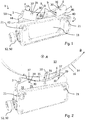
- Fig. 1 shows a schematic view of a scanning head 1 with a housing 2 and a first, arranged on the housing 2 sensor device 3 with a first sensor surface 4 and a second, arranged on the housing 2, in a circumferential direction U of a shaft or other rotatable member (not shown)
- the sensor device 5 arranged offset to the first sensor device 3 has a second sensor surface 6.
- the two sensor devices 4, 6 are set for external scanning of a shaft 13. They point to each other.
- the two sensor surfaces 4, 6 are opposite to the determination of the angular position of a material measure and scan them.
- a sensor surface 4, 6 may define a preferred direction along which the measurement is particularly efficient. Such a preferred direction can be approximately perpendicular to the extent of the sensor surface 4, 6.
- the two sensor surfaces 4, 6 are offset from each other in the circumferential direction and inclined to each other so that the respective preferred direction is directed to the axis of rotation of the rotatable component.
- the sensor surfaces 4, 6 can be arranged in at least two angular positions relative to one another.
- the first and the second sensor device 3, 5 are each pivotally mounted on the housing 2 via an axis 30.
- the optional slot-shaped recesses 8 on the sensor devices 3, 5 make it possible for the sensor devices 3, 5 to be guided guided within a continuous range.
- Each of the two sensor devices 3, 5 has a fixing device 9, for example in the form of a screw, which projects through the slot-shaped recess 8 and fixes the sensor device 3 or 5 respectively.
- the scanning head 1 shown here thus enables a fixation of first and second sensor surface 4, 6 independently of each other in an arbitrary angular position to each other within a continuous range.
- the scanning head 1 designed in this way can be adapted to different shaft diameters.
- slot-shaped recesses could be present on the housing 2 in order to enable pivoting.
- the sensor devices 3, 5 are provided with connecting elements with signal processing electronics (not shown) in a cavity 11 of Scanning head 1 connected.
- This signal processing electronics can serve, for example, to further process the sensor signals and already output a finished position signal, and / or speed signals and / or acceleration signal, which is output via the output 12.
- a scanning head 1 is shown together with a strap 14.
- the clamping band 14 is tensioned by means of a turnbuckle (not shown) on a shaft 13, whereby it rests firmly on the circumference of the shaft 13. Outside the range of the turnbuckle, the tension band 14 has a material measure 16. In this case, it is a magnetic material measure 16 that is detected by the magnetically measuring sensor devices 3, 5.
- the scanning head 1 has two sensor devices 3, 5, so that at least one sensor device 3, 5 can detect and measure the material measure 16.
- the outer surfaces of the sensor devices 3, 5 pointing toward the shaft 13 and the outer surface of the scanning head 1 facing the shaft 13 are slightly convex, so that mounting on differently sized shafts is possible. Due to the convex configuration, it is additionally possible to arrange the sensor surfaces 4, 6 in such a way that they are aligned with each other, whereby not only the rotational movement of a shaft, but also Also, a linear movement of a flat surface can be detected. Even the attachment inside a large hollow shaft is possible by this configuration.
- this has two elongated holes 21, in the fasteners, such as screws, are insertable.
- the distance between the two sensor surfaces 4, 6 can be adjusted, for example, in that the sensor units can be arranged, mounted or fastened at different distances from each other.
- the in the Fig. 1 to 4 shown sensor devices 3, 5 are independently pivotable. This makes it possible that the scanning head 1 can be arranged relative to the shaft 13 in a comparatively wide range. In the Fig. 2 the scanning head 1 could also be arranged further to the left or further to the right. To compensate for this offset, one of the two sensor devices 3 or 5 and thus the one sensor surface 4 or 6 would have to be pivoted further inwards and the other sensor unit 5 or 3 with the other sensor surface 6 or 4 further outwards.
- the two sensor devices 3, 5 and thus the two sensor surfaces 4, 6 could be pivotally coupled together, for example via a transmission (not shown) or via individual drives.
- a transmission not shown
- individual drives Such an embodiment would simplify the adaptation to the shaft diameter, since only one sensor device 3 or 5 would have to be adjusted and the other sensor device 5 or 3 would automatically be correctly adjusted.
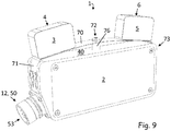
- the first sensor surface 4 and the second sensor surface 6 point at least partially in the same direction as an end face 40 of the housing 2, ie the normal directions of the sensor surfaces 4 and 6 have components that are parallel to the surface normal of the end face 40.
- the two sensor surfaces 4, 6 and the end face 40 each have from the housing 2 to the outside.
- the sensor surfaces 4, 6 are the front side 40 thereby preceded. They are located further outside than the front side 40.
- the sensor devices 3, 5 are located between the sensor surfaces 4, 6 and the end face 40.
- the sensor devices 3, 5 are each rotatable about axes of rotation 30 which extend through axes 37.
- the axes 37 are formed by projections 38 on the sensor devices 3, 5, which are arranged in holes 39 on the side plates 31 (see FIG Fig. 2 ).
- the axes of rotation 30 are located on the sensor surfaces 4, 6 forming sides 34, 36 of the sensor devices 3, 5.
- the axes of rotation 30 are thus closer to the sensor surfaces 4, 6 forming sides 34, 36 of the sensor devices 3, 5 than to the In particular, they are located centrally with respect to the sensor surfaces 4, 6. Due to this configuration, a change in the distance between the sensor surfaces 4, 6 to each other in a change in the angular position is minimized.
- the sensor devices 3, 5 are each designed as separate components and are located completely in front of the end face 40 of the housing 2.
- Fig. 2 is the readhead off Fig. 1 in fully assembled condition, ie without the in Fig. 1 missing parts shown.
- the two sensor devices 3, 5 are mounted between two lateral plates 31, which serve together with an attractable screw 32 as a locking device 33, with which the angular positions of the two sensor devices 3, 5 are simultaneously fixed.
- the locking device 33 shown here is so one-handed operation.
- the two lateral plates 31 act as clamping elements 35, between which the sensor devices 3, 5 are arranged and with which the sensor devices 3, 5 can be clamped.
- the holes 39 that receive the axles 37 and thus serve as bearings for rotation about the rotation axis 30 are at the outer ends of the side plates 31 arranged.
- the side panels 31 protrude furthest from the housing 2 with respect to a height direction H.
- the side plates 31 have a concave shape in order to be able to absorb the wave as well as possible in the case of external scanning. Laterally outwardly, the plates 31 protrude less far from the housing 2 in order to allow an as close as possible placement of the scanning head 1 on the inner surface of the hollow shaft at a ggiabtastung a hollow shaft.
- the measurement in Fig. 1 takes place tangentially.
- the two sensor surfaces 4, 6 extend in a direction which runs tangentially to the direction of movement B of the rotation of a point on the outer surface of the shaft 13.
- the sensor surfaces 4, 6 extend in a direction which is parallel to the axial direction A of the shaft 13. In the different angular positions, the sensor surfaces have different sized intermediate angles. When measured on a shaft, the two sensor surfaces are therefore not aligned.
- Fig. 3 an adjustment of the sensor devices 3, 5 is shown with which an internal scanning of a hollow shaft is possible.
- the sensor surfaces 4, 6 point away from each other. Due to the convex configuration of the outer surface of the scanning head 1, it is possible to measure even on an inner surface of the hollow shaft. For this purpose, the sensor surfaces 4, 6 are pivoted to the rest of the scanning head 1 out.
- measurement as in the measurement in the Fig. 1 to a tangential measurement.
- the sensor devices 3, 5 and / or the clamping elements 35 can have roughenings, corrugations or coatings with a high coefficient of friction.
- the scanning head 1 is turned off Fig. 3 , apart from an electrical connection element 50, a twofold rotational symmetry.
- a rotation about an axis of symmetry S by 180 ° forms the scanning head 1 again on itself.
- the sensor devices 3, 5 are interchanged, ie they change their places.
- the axis of symmetry S thereby extends centrally through the scanning head 1 and through the attractable screw 32. It extends from one side, which faces the shaft, to a side which faces away from the shaft when the scanning head 1 is mounted on the shaft for measurement ,
- Such a symmetrical design results in that the scanning head can be mounted in two different orientations and the installer does not have to pay attention to the correct orientation during assembly.
- the evaluation software which evaluates the signals coming from the scanning head 1, be designed so that it tolerates different mounting orientations.
- a measured in an outer region 51 thickness D1 of the scanning head 1, which is measured in a width direction W is smaller than a measured in an inner region 52 thickness D2 of the scanning head 1.
- the outer region 51 lies on the side on which the Sensor devices 3, 5 are.
- a third sensor means may be provided which is immovable relative to the remainder of the scanning head. This could, for example, be located between the two sensor surfaces 4, 6.
- Fig. 5 is the narrower design at the outer region 51 in a plan view clearly visible.
- the top view shows the view along a height direction H, wherein the height direction H is perpendicular to the longitudinal direction L and perpendicular to the width direction W.
- the scanning head 1 has a smaller extension than in the longitudinal direction L and in the height direction H.
- Fig. 6 two scanning heads 1 are shown, wherein a scanning head 1 scans a measuring scale 16 outside and the other scanning head 1, the measuring scale 16 scans inside. This shows that the same scanning head 1 can be used for scanning both from the inside and from the outside by rotation of the sensor devices 3, 5.
- the scanning head 1 In addition to the twofold rotational symmetry about the axis S passing through the central screw along the height direction H, the scanning head 1, like the other scanning heads, has a mirror symmetry with respect to a plane parallel to that through the height directions H and the longitudinal direction L defined plane extends and passes through the center of the housing. It is thereby achieved that in a rotation about the longitudinal direction L, as for example in the two scanning heads in Fig. 6 has occurred, no offset of the sensor devices 3, 5 along the width direction W occurs.
- a further embodiment of a scanning head 1 is shown.
- the scanning head 1 shown is set for scanning an outer surface of a shaft.
- the scanning head 1 has a leaf spring 70. On the leaf spring 70, the two sensor devices 3, 5 are fixed.
- the leaf spring 70 is fastened to the housing 2 at its ends 71, 73. This attachment is variable. At each end, there are two elongated holes 74 in the leaf spring 70, so that the ends 71, 73 in the height direction H can be variably fixed to the housing 2.
- the fastening takes place here by means of screws 75, which pinch the leaf spring 70 between the screw head and the housing 2.
- screws 75 which pinch the leaf spring 70 between the screw head and the housing 2.
- the leaf spring 70 can attach to the housing 2 in the region of the center 72 of the leaf spring 70 in height direction H be variable.
- the same angular positions can be achieved if the attachment of the leaf spring 70 is changed at the ends 71, 73 and at the center 72 by the same amount in the height direction H.
- Each of the sensor devices 3, 5 is arranged between an end 71 or 73 and the center 72 of the leaf spring 70. As a result, each of the sensor devices 3, 5 can be adjusted independently of the other sensor device 5, 3. At the same time, each sensor device 3, 5 is placed at a fixed location, since the leaf spring has an elastic projection.
- the leaf spring 70 functions here as a carrier element for fastening the sensor device 3, 5.
- the in Fig. 7 Scanning head 1 shown is also applicable to an axial measurement.
- an axial measurement is measured not on an outer or inner surface of a shaft, but on an end face of the shaft.
- the two sensor surfaces 4, 6 scan a material measure, for example in the form of a code track, which is arranged on the end face (not shown).
- the two sensor surfaces 4, 6 point towards the end face. They extend along a radial direction of the shaft and in a direction tangential to the direction of movement of the rotation of a point on the end face of the shaft. They are therefore parallel to the end face of the shaft.
- the first sensor device scans a finely resolved material measure.
- the second sensor device scans the finely resolved material measure and a roughly resolved material measure. For this purpose, it is measured wider in the radial direction than the first sensor device. It may have one wide or two narrower sensor surfaces (not shown).
- Fig. 8 the scanning head 1 is off Fig. 7 shown in FIG Fig. 8 is set for measuring or scanning an inner surface of a hollow shaft.
- the ends 71, 73 of the leaf spring 70 are pushed along the height direction H to the housing as in Fig. 8 , so that the sensor devices 3, 5 bear against the housing 2 at their outer ends.
- the leaf spring 70 is spaced from the housing 2 of a spacer element 76. This spacing element may for example be made variable, so that attachment of the leaf spring 70 at variable distances from the housing 2 is possible.
- the thickness of the leaf spring 70 and thus its hardness should be chosen so that a deformation is still possible, however, an unnecessary vibration behavior of the spring and the sensor devices 3, 5 mounted thereon is largely suppressed.
- the sensor surfaces 4, 6 upstream of an end face 40 of the housing 2.
- the sensor devices 3, 5 are again located between the sensor surfaces 4, 6 and the end face 40.
- the sensor devices 3, 5 are again separate components and are located completely in front of the end face 40.
- the sensor devices 3, 5 from the FIGS. 7 and 8 are rotatable. Unlike the previous embodiments, however, the rotation axis is not fixed to an axis 7 or 37. Rather, the axis of rotation about which the sensor devices 3, 5 are rotated, moves during the movement.
- the leaf spring 70 can be fixed in different positions fixed to the housing 2.
- a scanning head 1 can be seen, the scanning of the FIGS. 7 and 8 similar.
- a plug face 53 of a connection element 50 obliquely away from an end face 40 of the housing 2 away. This allows a more compact design than an embodiment in which the plug face 53 points in the longitudinal direction L, in which the end face 40 extends.
Landscapes
- Physics & Mathematics (AREA)
- General Physics & Mathematics (AREA)
- Length Measuring Devices With Unspecified Measuring Means (AREA)
Claims (15)
- Tête de détection (1) d'un codeur pour détection de paramètre de situation et/ou de mouvement, comme par exemple la position, la vitesse et l'accélération, entourée d'un boîtier (2) avec une face avant (40), un premier système de capteur (3) disposé sur le boîtier (2) avec une première surface de détecteur (4) dirigée du moins partiellement dans le même sens que la face avant (40), et un second système de capteur (5) disposé de manière décalée sur le boîtier (2) avec une seconde surface de détecteur (6), dirigée aussi du moins partiellement dans le même sens que la face avant (40), le premier et le second système de capteur (3, 5) pouvant être disposés dans au moins deux positions angulaires différentes des surfaces des détecteurs (4, 6) l'une par rapport à l'autre sur le boîtier (2) et les surfaces de détecteurs (4, 6) étant placées devant la face avant (40), les systèmes de capteurs (3, 5) se trouvant entre les surfaces des détecteurs (4, 6) et la face avant (40), les systèmes de capteurs (3, 5) étant des composants séparés et se trouvant entièrement devant la face avant (40) et au moins un système de capteur (3, 5) étant disposé, apposé ou fixé de manière orientable sur le boîtier (2) afin de permettre les deux positions angulaires différentes des surfaces des détecteurs (4, 6).
- Tête de détection (1) selon la revendication 1, caractérisée en ce sens qu'au moins l'un des systèmes de capteurs (3, 5) est disposé, apposé ou fixé de manière orientable sur le boîtier (2).
- Tête de détection (1) selon une des revendications précédentes, caractérisée en ce sens que les systèmes de capteurs (3, 5) sont respectivement orientables sur un axe de rotation (30) et que les axes de rotation (30) des systèmes de capteurs (3, 5) se trouvent sur les côtés (34, 36) formant les surfaces des détecteurs (4, 6) des systèmes de capteurs (3, 5).
- Tête de détection (1) selon une des revendications précédentes, caractérisée en ce sens que les systèmes de capteurs (3,5) sont respectivement orientables sur un axe de rotation (30) et que les axes de rotation (30) se trouvent à l'extérieur du boîtier (2).
- Tête de détection (1) selon une des revendications précédentes, caractérisée en ce sens que les systèmes de capteurs (3, 5) sont respectivement orientables sur un axe de rotation (30) et que les axes de rotation (30) se trouvent sur ou devant la face avant (40) du boîtier (2).
- Tête de détection (1) selon une des revendications précédentes, caractérisée en ce sens qu'il est prévu un dispositif d'arrêt (33) agissant simultanément sur les deux systèmes de capteurs (3, 5), dispositif par le biais duquel les positions angulaires des deux systèmes de capteurs (3, 5) peuvent être fixées.
- Tête de détection (1) selon la revendication 6, caractérisée en ce sens que le dispositif d'arrêt (33) présente au mois deux éléments de blocage (35) entre lesquels est disposé au moins un des systèmes de capteurs (3, 5).
- Tête de détection (1) selon une des revendications précédentes, caractérisée en ce sens qu'il est respectivement prévu une cavité (8) en forme de fente sur les systèmes de capteurs (3, 5) de sorte que les systèmes de capteurs (3, 5) puisse être orientés au sein d'une plage continue.
- Tête de détection (1) selon une des revendications précédentes, caractérisée en ce sens que la tête de détection (1), mis à part un élément de raccordement (50), présente pour l'essentiel une symétrie en rotation binaire.
- Tête de détection (1) selon une des revendications précédentes, caractérisée en ce sens que les systèmes de capteurs (3, 5) et/ ou le boîtier (2) et / ou les éléments de blocage (35) présentent des aides à l'alignement sous forme de repères visibles de l'extérieur, chaque repère étant associé à une position angulaire des systèmes de capteurs prédéterminée (3, 5).
- Tête de détection (1) selon une des revendications précédentes, caractérisée en ce sens que les systèmes de capteurs (3, 5) sont disposés sur un ressort à lame (70) lequel est fixé au boîtier (2) en au moins deux points de fixation.
- Tête de détection (1) selon la revendication 11, caractérisée en ce sens que le ressort à lame (70) est fixé au boîtier (2) à ses deux extrémités (71, 73) et en son milieu (72) et que respectivement un système de capteur (3,5) est disposé entre une extrémité (71,73) et le milieu (72).
- Tête de détection (1) selon la revendication 11 ou 12, caractérisée en ce sens que le ressort à lame (70) est peut être fixé au boîtier (2) en différentes positions bombées.
- Tête de détection (1) selon une des revendications précédents, caractérisée en ce sens qu'un élément de raccordement électrique (50) est doté d'un connecteur à configuration spéciale (53) partant en diagonale à l'opposé de la face avant (40).
- Tête de détection (1) selon une des revendications précédents, caractérisée en ce sens que les surfaces des détecteurs (4, 6) de la face avant du composant (13) orientable sont disposés à l'opposé et que, depuis les surfaces des détecteurs (4, 6), un étalon (16) prévu sur la face frontale peut être détecté.
Priority Applications (1)
| Application Number | Priority Date | Filing Date | Title |
|---|---|---|---|
| EP14167295.6A EP2801796B1 (fr) | 2013-05-07 | 2014-05-07 | Tête de sondage |
Applications Claiming Priority (2)
| Application Number | Priority Date | Filing Date | Title |
|---|---|---|---|
| EP13166894.9A EP2801795A1 (fr) | 2013-05-07 | 2013-05-07 | Tête de balayage pour un capteur |
| EP14167295.6A EP2801796B1 (fr) | 2013-05-07 | 2014-05-07 | Tête de sondage |
Publications (2)
| Publication Number | Publication Date |
|---|---|
| EP2801796A1 EP2801796A1 (fr) | 2014-11-12 |
| EP2801796B1 true EP2801796B1 (fr) | 2017-10-25 |
Family
ID=48236777
Family Applications (3)
| Application Number | Title | Priority Date | Filing Date |
|---|---|---|---|
| EP13166894.9A Ceased EP2801795A1 (fr) | 2013-05-07 | 2013-05-07 | Tête de balayage pour un capteur |
| EP14167295.6A Active EP2801796B1 (fr) | 2013-05-07 | 2014-05-07 | Tête de sondage |
| EP14723410.8A Active EP2994723B1 (fr) | 2013-05-07 | 2014-05-07 | Tête de balayage pour un capteur |
Family Applications Before (1)
| Application Number | Title | Priority Date | Filing Date |
|---|---|---|---|
| EP13166894.9A Ceased EP2801795A1 (fr) | 2013-05-07 | 2013-05-07 | Tête de balayage pour un capteur |
Family Applications After (1)
| Application Number | Title | Priority Date | Filing Date |
|---|---|---|---|
| EP14723410.8A Active EP2994723B1 (fr) | 2013-05-07 | 2014-05-07 | Tête de balayage pour un capteur |
Country Status (4)
| Country | Link |
|---|---|
| US (1) | US10066963B2 (fr) |
| EP (3) | EP2801795A1 (fr) |
| DE (2) | DE102014006456B4 (fr) |
| WO (1) | WO2014180879A1 (fr) |
Families Citing this family (2)
| Publication number | Priority date | Publication date | Assignee | Title |
|---|---|---|---|---|
| EP3153821A1 (fr) * | 2015-10-09 | 2017-04-12 | Siko GmbH | Système de détection |
| CN117010420A (zh) * | 2018-06-08 | 2023-11-07 | 深圳盈达信息科技有限公司 | 扫描头能转动的pda |
Family Cites Families (16)
| Publication number | Priority date | Publication date | Assignee | Title |
|---|---|---|---|---|
| US3674934A (en) * | 1970-02-24 | 1972-07-04 | Us Navy | Minimum shift keyed (msk) phase measurement device |
| GB1444851A (en) * | 1973-08-07 | 1976-08-04 | Oelsch Fernsteuergeraete | Photoelectric sensor head |
| US4289983A (en) * | 1979-06-29 | 1981-09-15 | International Business Machines Corporation | Encoder for monitoring bidirectional motion |
| US4414675A (en) * | 1981-08-05 | 1983-11-08 | Motorola, Inc. | MSK and OK-QPSK signal demodulator |
| US4669095A (en) * | 1985-09-27 | 1987-05-26 | Motorola, Inc. | Maximum distance from zero crossing MSK demodulator |
| JP3321224B2 (ja) * | 1992-03-13 | 2002-09-03 | ティーディーケイ株式会社 | 移動物体検出装置 |
| JP3114553B2 (ja) * | 1995-02-17 | 2000-12-04 | 富士写真光機株式会社 | 超音波診断装置 |
| DE19612337A1 (de) * | 1996-03-28 | 1997-10-02 | Vdo Schindling | Drehzahlsensor |
| DE10354458A1 (de) * | 2003-11-21 | 2005-06-23 | Valeo Schalter Und Sensoren Gmbh | Sensorhalteeinrichtung zur Halterung von Umfelderfassungssensoren |
| DE102005056207A1 (de) * | 2005-11-25 | 2007-06-06 | Robert Bosch Gmbh | Sensorsystem und Verfahren zu dessen Herstellung |
| JP5038764B2 (ja) * | 2007-04-05 | 2012-10-03 | 株式会社東芝 | 超音波診断装置 |
| DE102007022765A1 (de) * | 2007-05-15 | 2008-11-20 | Knorr-Bremse Systeme für Nutzfahrzeuge GmbH | Sensormodul mit einem schwenkbaren Sensor |
| JP5394299B2 (ja) * | 2010-03-30 | 2014-01-22 | 富士フイルム株式会社 | 超音波診断装置 |
| DE102010061737A1 (de) * | 2010-11-22 | 2012-05-24 | Baumer Innotec Ag | Absolutwertgeber mit Sprungstelle in kodierter Absolutlage |
| DE102010061738A1 (de) | 2010-11-22 | 2012-04-26 | Baumer Innotec Ag | Verfahren und Inkrementalwertgeber zur Bestimmung einer Istlage eines Körpers entlang eines Messweges mit einer wenigstens eine Lücke aufweisenden Maßverkörperung |
| SE539190C2 (sv) * | 2012-05-04 | 2017-05-09 | Leine & Linde Ab | Ett sensorhuvud för en pulsgivare |
-
2013
- 2013-05-07 EP EP13166894.9A patent/EP2801795A1/fr not_active Ceased
-
2014
- 2014-05-06 DE DE102014006456.5A patent/DE102014006456B4/de not_active Expired - Fee Related
- 2014-05-06 DE DE102014006455.7A patent/DE102014006455A1/de not_active Withdrawn
- 2014-05-07 WO PCT/EP2014/059295 patent/WO2014180879A1/fr not_active Ceased
- 2014-05-07 EP EP14167295.6A patent/EP2801796B1/fr active Active
- 2014-05-07 EP EP14723410.8A patent/EP2994723B1/fr active Active
- 2014-05-07 US US14/896,149 patent/US10066963B2/en active Active
Non-Patent Citations (1)
| Title |
|---|
| None * |
Also Published As
| Publication number | Publication date |
|---|---|
| WO2014180879A1 (fr) | 2014-11-13 |
| EP2801795A1 (fr) | 2014-11-12 |
| DE102014006455A1 (de) | 2014-11-13 |
| EP2801796A1 (fr) | 2014-11-12 |
| EP2994723A1 (fr) | 2016-03-16 |
| DE102014006456B4 (de) | 2020-10-15 |
| DE102014006456A1 (de) | 2014-11-13 |
| EP2994723B1 (fr) | 2017-09-20 |
| US10066963B2 (en) | 2018-09-04 |
| US20160131502A1 (en) | 2016-05-12 |
Similar Documents
| Publication | Publication Date | Title |
|---|---|---|
| DE102010001308B4 (de) | Hubsensor | |
| EP2689225B1 (fr) | Détecteur de couple magnéto-élastique | |
| EP2093537A1 (fr) | Système et procédé pour déterminer l'alignement de deux pièces de machine rotatives, l'alignement de deux cylindres creux, ou pour éprouver la rectitude d'u component | |
| EP1464935A1 (fr) | Appareil pour détecter le couple de rotation d'un arbre rotatif | |
| DE10240049A1 (de) | Drehmomentsensor | |
| EP1353150A2 (fr) | Capteur d'angle | |
| EP2255207B1 (fr) | Systeme de mesure angulaire et procede de fabrication d'un systeme de mesure angulaire | |
| EP2801796B1 (fr) | Tête de sondage | |
| DE112010004387T5 (de) | Drehpositionssensor an durchgangswelle | |
| EP3279615B1 (fr) | Dispositif de mesure de longueur | |
| EP0617253B1 (fr) | Dispositif de mesure pour déterminer la forme des cylindres | |
| EP2894448B1 (fr) | Dispositif de détection de l'état d'un élément de machine | |
| DE102019124972A1 (de) | Sensoranordnung zur Erfassung eines Lenkmomentes sowie einer absoluten Winkelposition und Sensorvorrichtung mit dieser Sensoranordnung | |
| DE20305732U1 (de) | Vorrichtung zum Bestimmen eines auf eine Welle ausgeübten Drehmoments | |
| EP2189763A2 (fr) | Dispositif et procédé d'agencement d'un boîtier dans une position prédéfinie par rapport à un objet de référence | |
| EP2257768B1 (fr) | Système de mesure angulaire | |
| EP1210572B1 (fr) | Mesure d'un angle de rotation a l'aide de resonateurs a conducteurs sous forme de microbandes (2,4gh, 2 degres) | |
| EP1600737B1 (fr) | Dispositif de mesure d'angle de rotation | |
| DE10001346A1 (de) | Drehmomenterfassungsvorrichtung | |
| EP3064793A1 (fr) | Système de capteur de mouvement pour véhicules sur rail | |
| EP3658861B1 (fr) | Capteur d'angle doté du guide d'ondes creux annulaire en tant qu'échelle | |
| DE102008012693A1 (de) | Drehgebersystem und Verfahren zur Einrichtung desselben | |
| DE102007033751A1 (de) | Anordnung eines Spulenpaares in einem örtlichen Messbereich | |
| EP4323727B1 (fr) | Système électromagnétique de mesure de course d'un piston, support d'aimant ainsi qu'utilisation d'un système électromagnétique de mesure de course d'un piston | |
| EP1643217B1 (fr) | Unité de balayage et arrangement pour mesurer une position |
Legal Events
| Date | Code | Title | Description |
|---|---|---|---|
| PUAI | Public reference made under article 153(3) epc to a published international application that has entered the european phase |
Free format text: ORIGINAL CODE: 0009012 |
|
| 17P | Request for examination filed |
Effective date: 20140507 |
|
| AK | Designated contracting states |
Kind code of ref document: A1 Designated state(s): AL AT BE BG CH CY CZ DE DK EE ES FI FR GB GR HR HU IE IS IT LI LT LU LV MC MK MT NL NO PL PT RO RS SE SI SK SM TR |
|
| AX | Request for extension of the european patent |
Extension state: BA ME |
|
| R17P | Request for examination filed (corrected) |
Effective date: 20150508 |
|
| RBV | Designated contracting states (corrected) |
Designated state(s): AL AT BE BG CH CY CZ DE DK EE ES FI FR GB GR HR HU IE IS IT LI LT LU LV MC MK MT NL NO PL PT RO RS SE SI SK SM TR |
|
| 17Q | First examination report despatched |
Effective date: 20170125 |
|
| GRAP | Despatch of communication of intention to grant a patent |
Free format text: ORIGINAL CODE: EPIDOSNIGR1 |
|
| INTG | Intention to grant announced |
Effective date: 20170803 |
|
| GRAS | Grant fee paid |
Free format text: ORIGINAL CODE: EPIDOSNIGR3 |
|
| GRAA | (expected) grant |
Free format text: ORIGINAL CODE: 0009210 |
|
| AK | Designated contracting states |
Kind code of ref document: B1 Designated state(s): AL AT BE BG CH CY CZ DE DK EE ES FI FR GB GR HR HU IE IS IT LI LT LU LV MC MK MT NL NO PL PT RO RS SE SI SK SM TR |
|
| REG | Reference to a national code |
Ref country code: GB Ref legal event code: FG4D Free format text: NOT ENGLISH |
|
| REG | Reference to a national code |
Ref country code: CH Ref legal event code: EP |
|
| REG | Reference to a national code |
Ref country code: AT Ref legal event code: REF Ref document number: 940349 Country of ref document: AT Kind code of ref document: T Effective date: 20171115 |
|
| REG | Reference to a national code |
Ref country code: IE Ref legal event code: FG4D Free format text: LANGUAGE OF EP DOCUMENT: GERMAN |
|
| REG | Reference to a national code |
Ref country code: DE Ref legal event code: R096 Ref document number: 502014005933 Country of ref document: DE |
|
| REG | Reference to a national code |
Ref country code: SE Ref legal event code: TRGR |
|
| REG | Reference to a national code |
Ref country code: NL Ref legal event code: MP Effective date: 20171025 |
|
| REG | Reference to a national code |
Ref country code: LT Ref legal event code: MG4D |
|
| PG25 | Lapsed in a contracting state [announced via postgrant information from national office to epo] |
Ref country code: NL Free format text: LAPSE BECAUSE OF FAILURE TO SUBMIT A TRANSLATION OF THE DESCRIPTION OR TO PAY THE FEE WITHIN THE PRESCRIBED TIME-LIMIT Effective date: 20171025 |
|
| PG25 | Lapsed in a contracting state [announced via postgrant information from national office to epo] |
Ref country code: ES Free format text: LAPSE BECAUSE OF FAILURE TO SUBMIT A TRANSLATION OF THE DESCRIPTION OR TO PAY THE FEE WITHIN THE PRESCRIBED TIME-LIMIT Effective date: 20171025 Ref country code: LT Free format text: LAPSE BECAUSE OF FAILURE TO SUBMIT A TRANSLATION OF THE DESCRIPTION OR TO PAY THE FEE WITHIN THE PRESCRIBED TIME-LIMIT Effective date: 20171025 Ref country code: NO Free format text: LAPSE BECAUSE OF FAILURE TO SUBMIT A TRANSLATION OF THE DESCRIPTION OR TO PAY THE FEE WITHIN THE PRESCRIBED TIME-LIMIT Effective date: 20180125 Ref country code: FI Free format text: LAPSE BECAUSE OF FAILURE TO SUBMIT A TRANSLATION OF THE DESCRIPTION OR TO PAY THE FEE WITHIN THE PRESCRIBED TIME-LIMIT Effective date: 20171025 |
|
| REG | Reference to a national code |
Ref country code: FR Ref legal event code: PLFP Year of fee payment: 5 |
|
| PG25 | Lapsed in a contracting state [announced via postgrant information from national office to epo] |
Ref country code: RS Free format text: LAPSE BECAUSE OF FAILURE TO SUBMIT A TRANSLATION OF THE DESCRIPTION OR TO PAY THE FEE WITHIN THE PRESCRIBED TIME-LIMIT Effective date: 20171025 Ref country code: GR Free format text: LAPSE BECAUSE OF FAILURE TO SUBMIT A TRANSLATION OF THE DESCRIPTION OR TO PAY THE FEE WITHIN THE PRESCRIBED TIME-LIMIT Effective date: 20180126 Ref country code: HR Free format text: LAPSE BECAUSE OF FAILURE TO SUBMIT A TRANSLATION OF THE DESCRIPTION OR TO PAY THE FEE WITHIN THE PRESCRIBED TIME-LIMIT Effective date: 20171025 Ref country code: BG Free format text: LAPSE BECAUSE OF FAILURE TO SUBMIT A TRANSLATION OF THE DESCRIPTION OR TO PAY THE FEE WITHIN THE PRESCRIBED TIME-LIMIT Effective date: 20180125 Ref country code: LV Free format text: LAPSE BECAUSE OF FAILURE TO SUBMIT A TRANSLATION OF THE DESCRIPTION OR TO PAY THE FEE WITHIN THE PRESCRIBED TIME-LIMIT Effective date: 20171025 Ref country code: IS Free format text: LAPSE BECAUSE OF FAILURE TO SUBMIT A TRANSLATION OF THE DESCRIPTION OR TO PAY THE FEE WITHIN THE PRESCRIBED TIME-LIMIT Effective date: 20180225 |
|
| REG | Reference to a national code |
Ref country code: DE Ref legal event code: R097 Ref document number: 502014005933 Country of ref document: DE |
|
| PG25 | Lapsed in a contracting state [announced via postgrant information from national office to epo] |
Ref country code: CZ Free format text: LAPSE BECAUSE OF FAILURE TO SUBMIT A TRANSLATION OF THE DESCRIPTION OR TO PAY THE FEE WITHIN THE PRESCRIBED TIME-LIMIT Effective date: 20171025 Ref country code: CY Free format text: LAPSE BECAUSE OF FAILURE TO SUBMIT A TRANSLATION OF THE DESCRIPTION OR TO PAY THE FEE WITHIN THE PRESCRIBED TIME-LIMIT Effective date: 20171025 Ref country code: EE Free format text: LAPSE BECAUSE OF FAILURE TO SUBMIT A TRANSLATION OF THE DESCRIPTION OR TO PAY THE FEE WITHIN THE PRESCRIBED TIME-LIMIT Effective date: 20171025 Ref country code: DK Free format text: LAPSE BECAUSE OF FAILURE TO SUBMIT A TRANSLATION OF THE DESCRIPTION OR TO PAY THE FEE WITHIN THE PRESCRIBED TIME-LIMIT Effective date: 20171025 Ref country code: SK Free format text: LAPSE BECAUSE OF FAILURE TO SUBMIT A TRANSLATION OF THE DESCRIPTION OR TO PAY THE FEE WITHIN THE PRESCRIBED TIME-LIMIT Effective date: 20171025 |
|
| PG25 | Lapsed in a contracting state [announced via postgrant information from national office to epo] |
Ref country code: SM Free format text: LAPSE BECAUSE OF FAILURE TO SUBMIT A TRANSLATION OF THE DESCRIPTION OR TO PAY THE FEE WITHIN THE PRESCRIBED TIME-LIMIT Effective date: 20171025 Ref country code: PL Free format text: LAPSE BECAUSE OF FAILURE TO SUBMIT A TRANSLATION OF THE DESCRIPTION OR TO PAY THE FEE WITHIN THE PRESCRIBED TIME-LIMIT Effective date: 20171025 Ref country code: RO Free format text: LAPSE BECAUSE OF FAILURE TO SUBMIT A TRANSLATION OF THE DESCRIPTION OR TO PAY THE FEE WITHIN THE PRESCRIBED TIME-LIMIT Effective date: 20171025 Ref country code: IT Free format text: LAPSE BECAUSE OF FAILURE TO SUBMIT A TRANSLATION OF THE DESCRIPTION OR TO PAY THE FEE WITHIN THE PRESCRIBED TIME-LIMIT Effective date: 20171025 |
|
| PLBE | No opposition filed within time limit |
Free format text: ORIGINAL CODE: 0009261 |
|
| STAA | Information on the status of an ep patent application or granted ep patent |
Free format text: STATUS: NO OPPOSITION FILED WITHIN TIME LIMIT |
|
| PG25 | Lapsed in a contracting state [announced via postgrant information from national office to epo] |
Ref country code: MT Free format text: LAPSE BECAUSE OF FAILURE TO SUBMIT A TRANSLATION OF THE DESCRIPTION OR TO PAY THE FEE WITHIN THE PRESCRIBED TIME-LIMIT Effective date: 20171025 |
|
| 26N | No opposition filed |
Effective date: 20180726 |
|
| PG25 | Lapsed in a contracting state [announced via postgrant information from national office to epo] |
Ref country code: SI Free format text: LAPSE BECAUSE OF FAILURE TO SUBMIT A TRANSLATION OF THE DESCRIPTION OR TO PAY THE FEE WITHIN THE PRESCRIBED TIME-LIMIT Effective date: 20171025 |
|
| REG | Reference to a national code |
Ref country code: BE Ref legal event code: MM Effective date: 20180531 |
|
| PG25 | Lapsed in a contracting state [announced via postgrant information from national office to epo] |
Ref country code: MC Free format text: LAPSE BECAUSE OF FAILURE TO SUBMIT A TRANSLATION OF THE DESCRIPTION OR TO PAY THE FEE WITHIN THE PRESCRIBED TIME-LIMIT Effective date: 20171025 |
|
| REG | Reference to a national code |
Ref country code: IE Ref legal event code: MM4A |
|
| PG25 | Lapsed in a contracting state [announced via postgrant information from national office to epo] |
Ref country code: LU Free format text: LAPSE BECAUSE OF NON-PAYMENT OF DUE FEES Effective date: 20180507 |
|
| PG25 | Lapsed in a contracting state [announced via postgrant information from national office to epo] |
Ref country code: IE Free format text: LAPSE BECAUSE OF NON-PAYMENT OF DUE FEES Effective date: 20180507 |
|
| PG25 | Lapsed in a contracting state [announced via postgrant information from national office to epo] |
Ref country code: BE Free format text: LAPSE BECAUSE OF NON-PAYMENT OF DUE FEES Effective date: 20180531 |
|
| PG25 | Lapsed in a contracting state [announced via postgrant information from national office to epo] |
Ref country code: TR Free format text: LAPSE BECAUSE OF FAILURE TO SUBMIT A TRANSLATION OF THE DESCRIPTION OR TO PAY THE FEE WITHIN THE PRESCRIBED TIME-LIMIT Effective date: 20171025 |
|
| PG25 | Lapsed in a contracting state [announced via postgrant information from national office to epo] |
Ref country code: HU Free format text: LAPSE BECAUSE OF FAILURE TO SUBMIT A TRANSLATION OF THE DESCRIPTION OR TO PAY THE FEE WITHIN THE PRESCRIBED TIME-LIMIT; INVALID AB INITIO Effective date: 20140507 Ref country code: PT Free format text: LAPSE BECAUSE OF FAILURE TO SUBMIT A TRANSLATION OF THE DESCRIPTION OR TO PAY THE FEE WITHIN THE PRESCRIBED TIME-LIMIT Effective date: 20171025 |
|
| PG25 | Lapsed in a contracting state [announced via postgrant information from national office to epo] |
Ref country code: MK Free format text: LAPSE BECAUSE OF NON-PAYMENT OF DUE FEES Effective date: 20171025 |
|
| PG25 | Lapsed in a contracting state [announced via postgrant information from national office to epo] |
Ref country code: AL Free format text: LAPSE BECAUSE OF FAILURE TO SUBMIT A TRANSLATION OF THE DESCRIPTION OR TO PAY THE FEE WITHIN THE PRESCRIBED TIME-LIMIT Effective date: 20171025 |
|
| PGFP | Annual fee paid to national office [announced via postgrant information from national office to epo] |
Ref country code: CH Payment date: 20200522 Year of fee payment: 7 |
|
| REG | Reference to a national code |
Ref country code: AT Ref legal event code: MM01 Ref document number: 940349 Country of ref document: AT Kind code of ref document: T Effective date: 20190507 |
|
| PGFP | Annual fee paid to national office [announced via postgrant information from national office to epo] |
Ref country code: GB Payment date: 20200522 Year of fee payment: 7 |
|
| PG25 | Lapsed in a contracting state [announced via postgrant information from national office to epo] |
Ref country code: AT Free format text: LAPSE BECAUSE OF NON-PAYMENT OF DUE FEES Effective date: 20190507 |
|
| PGFP | Annual fee paid to national office [announced via postgrant information from national office to epo] |
Ref country code: FR Payment date: 20210521 Year of fee payment: 8 |
|
| PGFP | Annual fee paid to national office [announced via postgrant information from national office to epo] |
Ref country code: SE Payment date: 20210521 Year of fee payment: 8 |
|
| REG | Reference to a national code |
Ref country code: CH Ref legal event code: PL |
|
| GBPC | Gb: european patent ceased through non-payment of renewal fee |
Effective date: 20210507 |
|
| PG25 | Lapsed in a contracting state [announced via postgrant information from national office to epo] |
Ref country code: LI Free format text: LAPSE BECAUSE OF NON-PAYMENT OF DUE FEES Effective date: 20210531 Ref country code: CH Free format text: LAPSE BECAUSE OF NON-PAYMENT OF DUE FEES Effective date: 20210531 |
|
| PG25 | Lapsed in a contracting state [announced via postgrant information from national office to epo] |
Ref country code: GB Free format text: LAPSE BECAUSE OF NON-PAYMENT OF DUE FEES Effective date: 20210507 |
|
| REG | Reference to a national code |
Ref country code: DE Ref legal event code: R081 Ref document number: 502014005933 Country of ref document: DE Owner name: BAUMER GERMANY GMBH & CO. KG, DE Free format text: FORMER OWNER: BAUMER HUEBNER GMBH, 10589 BERLIN, DE |
|
| REG | Reference to a national code |
Ref country code: SE Ref legal event code: EUG |
|
| PG25 | Lapsed in a contracting state [announced via postgrant information from national office to epo] |
Ref country code: SE Free format text: LAPSE BECAUSE OF NON-PAYMENT OF DUE FEES Effective date: 20220508 |
|
| PG25 | Lapsed in a contracting state [announced via postgrant information from national office to epo] |
Ref country code: FR Free format text: LAPSE BECAUSE OF NON-PAYMENT OF DUE FEES Effective date: 20220531 |
|
| REG | Reference to a national code |
Ref country code: DE Ref legal event code: R084 Ref document number: 502014005933 Country of ref document: DE |
|
| REG | Reference to a national code |
Ref country code: DE Ref legal event code: R084 Ref document number: 502014005933 Country of ref document: DE |
|
| PGFP | Annual fee paid to national office [announced via postgrant information from national office to epo] |
Ref country code: DE Payment date: 20250519 Year of fee payment: 12 |