EP2801877A2 - PLC-Kommunikationssystem - Google Patents
PLC-Kommunikationssystem Download PDFInfo
- Publication number
- EP2801877A2 EP2801877A2 EP14164139.9A EP14164139A EP2801877A2 EP 2801877 A2 EP2801877 A2 EP 2801877A2 EP 14164139 A EP14164139 A EP 14164139A EP 2801877 A2 EP2801877 A2 EP 2801877A2
- Authority
- EP
- European Patent Office
- Prior art keywords
- communication
- plc
- node
- processing
- route
- Prior art date
- Legal status (The legal status is an assumption and is not a legal conclusion. Google has not performed a legal analysis and makes no representation as to the accuracy of the status listed.)
- Granted
Links
Images




Classifications
-
- G—PHYSICS
- G05—CONTROLLING; REGULATING
- G05B—CONTROL OR REGULATING SYSTEMS IN GENERAL; FUNCTIONAL ELEMENTS OF SUCH SYSTEMS; MONITORING OR TESTING ARRANGEMENTS FOR SUCH SYSTEMS OR ELEMENTS
- G05B19/00—Program-control systems
- G05B19/02—Program-control systems electric
- G05B19/04—Program control other than numerical control, i.e. in sequence controllers or logic controllers
- G05B19/05—Programmable logic controllers, e.g. simulating logic interconnections of signals according to ladder diagrams or function charts
- G05B19/058—Safety, monitoring
-
- G—PHYSICS
- G05—CONTROLLING; REGULATING
- G05B—CONTROL OR REGULATING SYSTEMS IN GENERAL; FUNCTIONAL ELEMENTS OF SUCH SYSTEMS; MONITORING OR TESTING ARRANGEMENTS FOR SUCH SYSTEMS OR ELEMENTS
- G05B19/00—Program-control systems
- G05B19/02—Program-control systems electric
- G05B19/418—Total factory control, i.e. centrally controlling a plurality of machines, e.g. direct or distributed numerical control [DNC], flexible manufacturing systems [FMS], integrated manufacturing systems [IMS] or computer integrated manufacturing [CIM]
- G05B19/4185—Total factory control, i.e. centrally controlling a plurality of machines, e.g. direct or distributed numerical control [DNC], flexible manufacturing systems [FMS], integrated manufacturing systems [IMS] or computer integrated manufacturing [CIM] characterised by the network communication
-
- H—ELECTRICITY
- H04—ELECTRIC COMMUNICATION TECHNIQUE
- H04L—TRANSMISSION OF DIGITAL INFORMATION, e.g. TELEGRAPHIC COMMUNICATION
- H04L12/00—Data switching networks
- H04L12/28—Data switching networks characterised by path configuration, e.g. LAN [Local Area Networks] or WAN [Wide Area Networks]
- H04L12/40—Bus networks
- H04L12/403—Bus networks with centralised control, e.g. polling
-
- H—ELECTRICITY
- H04—ELECTRIC COMMUNICATION TECHNIQUE
- H04L—TRANSMISSION OF DIGITAL INFORMATION, e.g. TELEGRAPHIC COMMUNICATION
- H04L41/00—Arrangements for maintenance, administration or management of data switching networks, e.g. of packet switching networks
- H04L41/06—Management of faults, events, alarms or notifications
- H04L41/0677—Localisation of faults
-
- H—ELECTRICITY
- H04—ELECTRIC COMMUNICATION TECHNIQUE
- H04L—TRANSMISSION OF DIGITAL INFORMATION, e.g. TELEGRAPHIC COMMUNICATION
- H04L43/00—Arrangements for monitoring or testing data switching networks
- H04L43/08—Monitoring or testing based on specific metrics, e.g. QoS, energy consumption or environmental parameters
- H04L43/0805—Monitoring or testing based on specific metrics, e.g. QoS, energy consumption or environmental parameters by checking availability
- H04L43/0811—Monitoring or testing based on specific metrics, e.g. QoS, energy consumption or environmental parameters by checking availability by checking connectivity
-
- H—ELECTRICITY
- H04—ELECTRIC COMMUNICATION TECHNIQUE
- H04L—TRANSMISSION OF DIGITAL INFORMATION, e.g. TELEGRAPHIC COMMUNICATION
- H04L43/00—Arrangements for monitoring or testing data switching networks
- H04L43/10—Active monitoring, e.g. heartbeat, ping or trace-route
-
- G—PHYSICS
- G05—CONTROLLING; REGULATING
- G05B—CONTROL OR REGULATING SYSTEMS IN GENERAL; FUNCTIONAL ELEMENTS OF SUCH SYSTEMS; MONITORING OR TESTING ARRANGEMENTS FOR SUCH SYSTEMS OR ELEMENTS
- G05B2219/00—Program-control systems
- G05B2219/10—Plc systems
- G05B2219/15—Plc structure of the system
- G05B2219/15026—Detection of data transmission faults
-
- H—ELECTRICITY
- H04—ELECTRIC COMMUNICATION TECHNIQUE
- H04L—TRANSMISSION OF DIGITAL INFORMATION, e.g. TELEGRAPHIC COMMUNICATION
- H04L12/00—Data switching networks
- H04L12/28—Data switching networks characterised by path configuration, e.g. LAN [Local Area Networks] or WAN [Wide Area Networks]
- H04L12/44—Star or tree networks
- H04L2012/445—Star or tree networks with switching in a hub, e.g. ETHERNET switch
-
- H—ELECTRICITY
- H04—ELECTRIC COMMUNICATION TECHNIQUE
- H04L—TRANSMISSION OF DIGITAL INFORMATION, e.g. TELEGRAPHIC COMMUNICATION
- H04L43/00—Arrangements for monitoring or testing data switching networks
- H04L43/16—Threshold monitoring
-
- Y—GENERAL TAGGING OF NEW TECHNOLOGICAL DEVELOPMENTS; GENERAL TAGGING OF CROSS-SECTIONAL TECHNOLOGIES SPANNING OVER SEVERAL SECTIONS OF THE IPC; TECHNICAL SUBJECTS COVERED BY FORMER USPC CROSS-REFERENCE ART COLLECTIONS [XRACs] AND DIGESTS
- Y02—TECHNOLOGIES OR APPLICATIONS FOR MITIGATION OR ADAPTATION AGAINST CLIMATE CHANGE
- Y02P—CLIMATE CHANGE MITIGATION TECHNOLOGIES IN THE PRODUCTION OR PROCESSING OF GOODS
- Y02P90/00—Enabling technologies with a potential contribution to greenhouse gas [GHG] emissions mitigation
- Y02P90/02—Total factory control, e.g. smart factories, flexible manufacturing systems [FMS] or integrated manufacturing systems [IMS]
Definitions
- This invention relates to a system for establishing communications between a PLC (programmable logic controller) and other devices/appliances, and more particularly, to a communication system which can find an abnormal portion in case of occurrence of abnormality in a communication line.
- PLC programmable logic controller
- a programmable logic controller (hereinafter referred to as PLC or programmable controller) is operated to establish communication with other processing devices.
- PLC programmable logic controller
- the PLC judges that a communication abnormality has occurred when a data sent from one station to another was unable to be received for a predetermined time period and after a timer reached a predetermined time-up limit. Further, according to another Patent Document 2, whether the data communication was successful or not, is confirmed based on the frequency of retrial processing by displaying the number of times of retrial processing.
- a PLC communication system comprises a programmable logic controller (PLC), a plurality of processing devices, at least three communication processing nodes provided at the PLC and at the plurality of processing devices respectively to establish communication among the PLC and the plurality of processing devices and an interconnecting device and a plurality of communication lines for connecting the communication processing nodes to form a communication route among the communication processing nodes, wherein the programmable logic controller (PLC) detects a communication failure state in the communication route formed by the communication processing nodes.
- PLC programmable logic controller
- a display device is installed which displays an abnormal portion in the communication route based on the number of occurrences of the detected communication failure state in the interconnecting device and the plurality of communication lines.
- the display device displays the abnormal portion in the communication route, excluding a portion forming a normal communication route from among the communication routes which are judged to be in the communication failure state in the interconnecting device and the plurality of communication lines.
- the display device displays a communication circuit including all of the communication routes and the abnormal portion in the communication routes by differentiating the abnormal portion from the other portions.
- the display device displays a portion in which the number of occurrences of the detected communication failure state is equal to or more than a first threshold value as the abnormal portion and a portion in which the number of occurrences of the detected communication failure state is less than the first threshold value and equal to or more than a second threshold value as a warning portion, wherein the display device displays the warning portion by differentiating from the abnormal portion and the other portions.
- the display device displays the number of occurrences of the communication failure state in the interconnecting device and the plurality of communication lines, respectively.
- an FL-net (FA LINK network) is used for the communication lines and each of the communication processing nodes receives and sends a token from one communication processing node after another and when the token is not received from a previous communication processing node, a retrial processing is executed, wherein a re-issued token is sent to a next communication processing node and the PLC recognizes the communication route connecting the previous and the next communication processing nodes to be the communication route which is in the communication failure state, after the retrial processing was executed with a predetermined number of times.
- the communication processing nodes send data to another communication processing node based on an address to which the data is to be sent and when the data cannot be sent, the retrial processing is executed to resend the data, wherein the PLC recognizes a route connecting the communication processing node which sends the data and the communication processing node which receives the data to be the route indicating the state of communication failure when such retrial processing is executed with a predetermined set number of times.
- the display device further displays the number of the times of retrial processing in the each of the communication processing nodes.
- the display device displays the abnormal portion based on the number of times of forming a route indicating the state of communication failure in the respective interconnecting device and the plurality of communication lines. Accordingly, more the number of times for forming the route indicating the state of communication failure, higher the probability that the portion is in abnormal state. Therefore, by displaying the portion depending on the number of times for forming the route indicating the state of communication failure, the worker of the system can easily specify the abnormal portion.
- the display device displays the number of times forming the state of communication failure and accordingly, what type of phenomenon is occurring in the abnormal portion can be confirmed. Further, when a plurality of portions is judged to be abnormal, actual abnormality test can be performed in accordance with the number of times forming the state of communication failure from the high number to the low number. This can detect the abnormal portion in early stage.
- the abnormal portion can be surely confirmed using for example, a TCP (Transmission Control Protocol).
- TCP Transmission Control Protocol
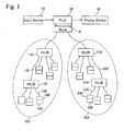
- the network system includes a programmable logic controller (PLC) 20 which controls machine tools and industrial robots and the system communicates with other processing devices.
- PLC programmable logic controller
- the network system includes, in addition to the PLC 20, an input device 10 for inputting parameters and information of communication line circuits to the PLC 20 and a display device 30 which displays the information from the PLC 20. Further, the system includes communication processing node 41 which is connected to the PLC 20. The processing node 41 is applicable to and compatible with the FL-net or DeviceNet (Registered Trademark).
- the network system in Fig. 1 establishes an FL-net network 100 and a DeviceNet network 200 through the communication processing node 41.
- the FL-net network 100 includes a plurality of processing devices 150 (hereinafter simply referred to as "devices"), a plurality of communication processing nodes 140 provided in each of the devices 150, interconnecting devices 110 (HUB) and a plurality of communication lines 120 for connecting the communication processing node 41 with each communication processing node 140 for data communication therebetween.
- the DeviceNet network 200 includes a plurality of processing devices 250 (hereinafter simply referred to as "devices”), a plurality of communication processing nodes 240 provided in each of the devices 250 serving as a slave node, interconnecting devices 210 and a plurality of communication lines 220 for connecting the communication processing node 41 as a master node to the slave nodes with each communication processing node 240 as a slave node for data communication therebetween.
- devices hereinafter simply referred to as "devices”
- interconnecting devices 210 for connecting the communication processing node 41 as a master node to the slave nodes with each communication processing node 240 as a slave node for data communication therebetween.
- Other devices 150 which are connected to the communication processing node 41 by the FL-net network 100 include, for example, other PLCs.
- Other devices 250 which are connected to the communication processing node 41 by the DeviceNet network 200 include other PLCs and I/O modules. It is noted that in the FL-net network 100 or the DeviceNet network 200, the number of devices 150 or 250 to be connected can be increased by using the HUB as the interconnecting devices 110 or 210. In the DeviceNet network 200, the interconnecting devices 210 are the HUBs such as T-branched taps.
- a worker or operator of the network inputs various values into the input device 10 for the PLC 20 and in addition, inputs setting change information to be displayed on the display device 30.
- the PLC 20 obtains state information on other devices 150 and 250 through the HUBs 110 and 210 and the communication lines 120 and 220 and executes calculations or operation processing. Further, the PLC 20 sends the result of calculations or the obtained state information of the devices to the other devices 150 and 250. Still further, the PLC 20 can confirm the ON or OFF state of the power sources of the communication processing nodes 140 and 240. The PLC 20 also detects the communication state between the communication processing nodes 140 and 240 whether the communication therebetween is in communication failure state or in normal state.
- the display device 30 displays all communication lines (network structural circuit). Further, the display device 30 displays the abnormal states and the warning states in different ways to differentiate from each other (for example, indicating with different colors). It is noted that the display device 30 may display only the information which can specify the abnormal states or the warning states, without displaying the entire system circuit.
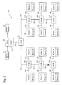
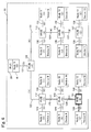
- the PLC communication system 101 corresponds to the portion of the network system illustrated in Fig. 1 and such portion includes input device 10, PLC 20, display device 30, communication processing node 41 and FL-net network 100. However, only a portion of the communication processing node in the FL-net network 100 is shown in Fig. 2 .
- the PLC communication system 101 includes the input device 10, PLC 20, display device 30, a communication processing node 1 (hereinafter simply referred to as "node” 1), nodes 2 through 13 connected with one another through the HUBs 111 through 117 as the interconnecting devices and the communication lines 121 through 139 (hereinafter referred to as simply "lines") and other devices 2 through 13 which are connected to the nodes 2 through 13 respectively.
- the PLC communication system 101 further includes hubs (HUB 111 through 117), which comply with the FL-net network, and the lines 121 through 139.
- the lines 121 through 139 connect the nodes 1 through 13 with the HUBs 111 through 117, respectively.
- each node 1 through 13 sends the data token (data transmission privilege) in a predetermined order.
- the order of sending the token is the order of node number (descending order of number).
- the order of sending the tokens is from node 1 to node 2, to node 3, to node 4, to node 5, to node 6, to node 7, to node 8, to node 9, to node 10, to node 11, to node 12 and to node 13.
- the node which holds the token can send the data to another node. In other words, only the node which holds the token can send the data to another node but the node which does not have token cannot send the data to another.
- the node 2 when the node 2 receives the token from the previous order node 1, the node 2 sends the data to the nodes 1 and 3 through 13 other than itself (node 2) within a predetermined time period from the receipt of the token and after the predetermined time period lapsed, the node 2 sends the token which has been received from the node 1, to the node 3.
- the node 6 could not receive the token from the previous order node 5 within the predetermined time period, the node 6 re-issues the token and sends the reissued token to the next order node 7. This processing is called as retrial processing. Thus, the node 6 issues a new token and sends the necessary data to other nodes 1 through 5 and 7 through 13 and then send the newly issued token to the next node 7 after the predetermined time lapsed.
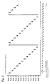
- the token is transferred to the node 3 from the node 2 and at the time t3, the token is transferred to the node 4 from the node 3 and in turn the token is transferred to the node 5 from the node 4 at the time t4.
- the token is sent to the next order node 6 from the node 5.
- the token cannot be sent to the node 6 from the node 5.
- the node 6 re-issues the token and at the time t6, the re-issued token is sent to the next node 7.
- the node 6 executes the retrial processing. It is noted here that the arrows with double line in Fig. 3 indicate that the re-issued token was transferred.
- the node 7 cannot receive the token sent from the node 6, because the line 128 is disconnected. Accordingly, the node 7 re-issues the token and the re-issued token is sent to the node 8 at the time t7. Thus, the node 7 also executes the retrial processing.
- the token is transferred from the node 8 to node 9, node 10 and node 11. Since the line 128 is broken, at the times t11 and t12, the nodes 12 and 13 cannot receive the token from the previous nodes 11 and 12, respectively. Therefore, the nodes 12 and 13 re-issue the token. In other words, the nodes 12 and 13 execute the retrial processing. At the times t14 through 26, the same process is performed as the process performed at the times t1 through t13.
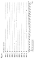
- the number of retries for each node 1 through 13 becomes the numbers shown in Fig. 4 .
- the number of retries of the nodes 1 through 5, 8 through 11 is zero from the time t1 to the time t30.
- the number of retries of the node 6 is one (1) at the time t6 and two (2) at the time t19.
- the number of retries of the node 7 is one (1) at the time t7 and two (2) at the time t20.
- the number of retries of the node 12 is one (1) at the time t12 and two (2) at the time t25.
- the number of retries of the node 13 is one (1) at the time t13 and two (2) at the time t26.
- the node with the retrial number is 1 or more than 1 is the subject node for judgment.
- the initial value "n” is 1, judgment for the node 1 is made whether the number of retrials is equal to or more than "k".
- the retrial number of the nodes 1 through 5 and 8 through 11 are all zero and accordingly the judgment indicates "No".
- the number of the nodes 6 and 7 and 12 and 13 is two (2) then, the judgment is "Yes".
- the retrial processing causing route is defined to be the route in state of communication failure (at the step S3).
- the node 6 has retried two times for sending token, the judgment at the step S2 is "Yes", and the communication route between the node 5 and the node 6 is judged to be the route of the state of communication failure.
- This route includes the route from line 135 to HUB 116, to line 134, to HUB 115, to line 131, to HUB 111, to line 122, to HUB 112, to line 125, to HUB 113, to line 128, to HUB 114 and to line 129.
- the process ends (at the step S4, Yes).
- the counter "n" of the node has not reached to the max value "n (max)" (at the step S4, No)
- number one (1) is added to the counter "n” (at the step S5) and repeats the process from the step S2.
- the PLC judges that the causing route for the retrial processing is the route of the state of communication failure, when the number of retrials is equal to or more than the number "k".
- the display 30 displays all communication lines as shown in Fig. 6 .
- the number of retrials is displayed with a bracketed numeral at each of the nodes 1 through 13.
- the numeral 2 is displayed with bracket and in the other nodes, the numeral zero (0) is displayed with bracket.
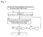
- the display device 30 performs the counting processing of the number of occurrences of communication failure.
- the counting processing for the number of occurrences of communication failure means the calculation processing for calculating values corresponding to the number of occurrences of forming the route of communication failure state in the HUBs 111 through 117 and the lines 121 through 139.
- the counter "j" of the route which is in the state of communication failure is set to be one (1) (at the step S11).
- the counter "j" corresponds to the number of the routes that indicated the state of communication failure by the processing of the PLC 20 as shown in the flowchart in Fig. 5 .
- the number one (1) is added to the number of times of the routes in the state of communication failure in the respective HUBs and the lines which become the state of communication failure (at the step S12).
- the route for forming the state of communication failure is formed by the HUBs and lines which connect the nodes 5 and 6, which are the HUBs 116, 115, 111, 112, 113 and 114 and the lines 135, 134, 131, 122, 125, 128 and 129.
- Each one (1) is added to the number which indicates the number of times forming the state of communication failure in these respective HUBs and the lines.
- the bracketed numerals which indicate the number of times of forming the route of the state of communication failure are displayed in the respective HUBs 111 through 117 and the lines 121 through 139 in the communication line circuit displayed on the display device 30.
- the bracketed numeral four (4) is indicated in the HUBs 116, 115, 111, 112, 113 and 114 and the lines 134, 131, 122, 125 and 128, while the bracketed numeral two (2) is indicated in the HUB 117 and the lines 137, 129 and 130.
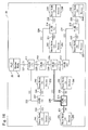
- the display device 30 judges whether a portion of the circuit is in abnormal state or in warning state. This judgment is made for the HUBs 111 through 117 and the lines 121 through 139, respectively. First, the display device 30 judges whether the number of times of the communication failure state is equal to or more than the first threshold value Th1 (at the step S21). It is noted here that the threshold value Th1 is assumed to be three (3). Accordingly, since each bracketed number indicated in the HUBs 114 and 116 is indicated as four (4) which is the number of times of forming the state of communication failure, the value is more than the assumed first threshold value 3.
- the normal communication route means that the route is in actually communicable state.
- the route connecting the node 7 and node 8 is a normal communication route.
- the portions forming this normal communication route in this case are HUBs 117, 116, 115, 111 and 112 and the lines 138, 137, 134, 131, 122 and 124 in Fig. 6 .
- the process ends without further processing.
- the portion is judged not to form a normal communication route
- the portion is judged to be in abnormal state (at the step S23, No) and then the program ends without further processing.
- the HUB 116 indicates four (4) times of forming the state of communication failure, but this Hub 116 actually forms a portion of the normal communication route and accordingly, the HUB 116 is not judged to be abnormal but judged to be normal.
- the HUB 114 and the line 128 indicate four (4) for the number of times of forming the state of communication failure and are not the portions forming the normal communication route. Accordingly, the HUB 114 and the line 128 are judged to be the abnormal portions.
- the display device 30 judges whether the indicated number is equal to or more than a second threshold value Th2 (step S24). Assuming that the value of the second threshold value Th2 is one (1), the HUB 117 and the line 129 indicating the number two (2) are judged to be the values more than the second threshold value Th2.
- the display device 30 judges whether the portion is forming a normal communication route or not (at the step S25).
- the normal communication route means as explained above that the route is in actually communicable state.
- the portion is judged to be not a normal communication route (at the step S25, No)
- the portion is judged to be in a warning state (at the step S26) and then the program ends without further processing.
- the number in the HUB 117 indicates two (2) times of forming the state of communication failure, but this Hub forms a portion of the normal communication route and accordingly, the HUB 117 is not judged to be in warning state but judged to be normal.
- the number in the line 129 indicates two (2) and is not a portion forming the normal communication route. Accordingly, the line 129 is judged to be a warning portion.
- the portion judged to be the abnormal state is illustrated with the bold double solid line and the portion judged to be the warning state is illustrated with the bold double dotted line.
- the portion judged to be normal is illustrated with thin solid line.
- the normal, abnormal and warning levels are distinctly illustrated and displayed differently.
- such distinction over the normal, abnormal and warning portions is made by differentiating the boldness of the line, type of the line or the like from one another.
- This distinction can be made by using differently colored lines for each portion or moreover, such distinction can be made by using lighting or flashing.
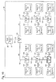
- the PLC communication system 101 displays actual abnormal portion. As shown in the drawing, assuming that the line 126 and the HUB 114 are in abnormal state, the nodes 4 through 7, 12 and 13 execute retrial processing and the display device 30 displays the state of the system 101 as shown in Fig. 10 . In Fig. 10 , the nodes 4 through 7, 12 and 13 are presumed to have executed the retrial processing two times, respectively.
- the line 128 and the HUB 114 are displayed as the abnormal portion and the lines 126, 129, 130 and 135 are illustrated as the warning portion on the display device 30 and the portions other than the abnormal or the warning portion are illustrated as the normal portion.
- the portion actually becoming abnormal includes the abnormal portion or the warning portion, the operator or worker of the system can find and specify an abnormal portion in early stage.
- the display device 30 displays the abnormal portions of the HUBs 111 through 117 and the lines 121 through 139 based on the number of times of forming the route which indicates the state of communication failure. As apparent from the explanation above, more the number of times of the route which indicates the state of communication failure, highly likely the route has an abnormal portion. Thus, by displaying the portions depending on the number of times of forming the route which is in the state communication failure on the display device 30, workers or the operators of the system can easily specify where the abnormal portions in the system are.
- the display device 30 displays the warning portions in addition to the abnormal portions distinctly differentiating from the abnormal portions. There may be some portions where likelihood of occurrence of abnormality in future is high, even though when the portions where the number of times of forming the state of communication failure is large, but not so large to form the route having the state of communication failure at present. By displaying such portions distinctly differentiating from the abnormal portions to be the warning portions, the worker of the system keeps on eyes to such warning portion not to be developed to the abnormal portion.
- the display device 30 displays all communication lines as a network and at the same time displays the abnormal and the warning portions differently from the other portions (normal portions) so that the abnormal portions can be easily located from the display.
- the display device 30 displays abnormal portions and warning portions from among the portions which have been judged to form a route of communication failure state, but excluding the portions forming the routes of normal communication state from among the HUBs 111 through 117 and the lines 121 through 139.
- the hubs are used to form a network, there would be a case wherein one communication route formed between certain two nodes may form another communication route formed between another certain two nodes and accordingly, there would be a case wherein even the communication route formed between certain two nodes is in normal state, the communication route formed between different two nodes may be in communication failure state.
- the portion forming the normal communication route may be also counted as a portion forming the abnormal communication route (the route forming the state of communication failure).
- the number of times of communication failure state in the HUB 116 is indicated as four (4). Therefore, even when the portion is counted as the state of communication failure, if such portion is actually in normal state, the portion is excluded from the counting of abnormal portions and warning portions so that an accurate counting can be performed to correctly specify the portions of actually abnormal or warning states.
- the display device 30 displays the number of times of the route forming the state of communication failure in respective HUBs 111 through 117 and the lines 121 through 139. By counting and displaying the number of times of the portions forming the state of communication failure, what is happening in the abnormal portions and the warning portions can be confirmed thereby. Further, if a plurality of portions is judged to be in abnormal state, the order of executing abnormality test can be performed, for example, in order from the largest number to the smallest. Thus, an abnormal state in the system can be detected in early stage.
- the display device 30 displays the number of retrial processing in every node of the system.
- occurrence of abnormality or warning stage can be predicted in early stage, considering the number of times of executing retrial processing.
- displaying the number of times of the retrials for each node can identify which node is in abnormal state. For example, if a plurality of portions is judged to be in abnormal state, the order of confirming an abnormality in the respective nodes can be decided, for example, in order from the largest number of times of retrial processing.
- a modified structure of the first embodiment will be explained hereinafter with reference to Fig. 11 .
- the number of times of communication failures displayed on each HUB 111 through 117 and each line 121 through 139 corresponds to the number of routes forming such communication failure state.
- the number of communication failures displayed on each HUB 111 through 117 and each line 121 through 139 corresponds to the number of times that the state of communication failure itself occurred from the time t1 to the time t30.
- the retrial processing is carried out at the time t6 from node 6 to node 7, at the time t7 from node 7 to node 8, at the time t12 from node 12 to node 13, at the time t13 from node 13 to node 1, at the time t19 from node 6 to node 7, at the time t20 from node 7 to node 8, at the time t25 from node 12 to node 13 and at the time t26 from node 13 to node 1 between the time t1 and the time t30.
- the HUB 113 forms all of the above retrial routes and is counted as eight (8) times of occurrence of communication failure state in total. Therefore, the display device 30 displays the bracketed number eight (8) for the HUB 113.
- the first threshold value Th1 for judging the abnormal portion and the second threshold value Th2 for judging the warning portion are set differently. According to this modified embodiment, the effects of the first embodiment can be similarly obtained.
- the display device 30 displays the abnormal and the warning portions excluding the portions forming the normal routes.
- the network structure which is formed by a plurality of and complex HUBs and the lines, a worker or an operator of the network can easily and surely specify the abnormal portions by structuring the system in a manner explained above. It is noted, however, that a smaller structured network may be sufficiently specify the abnormal portions even the normal portions forming the route of normal communication state are not excluded.
- Fig. 12 illustrates the judging process for the abnormal and the warning portions excluding the processes of judging whether or not forming normal route in the second embodiment.
- the step S31 whether or not the number of times of the communication failures is equal to or more than the first threshold value Th1 is judged at the step S31, if the judgment is Yes, (at the step S31, Yes), the portion is judged to be the abnormal portion (at the step S32).
- Whether or not the number of times of the communication failures is less than the first threshold value Th1 is judged at the step S31, if the judgment is No, (at the step S31, No), whether or not the number of times of the communication failures is equal to or than the second threshold value Th2 is judged at the step S33. If the judgment is Yes (at the step S33), the portion is judged to be the warning portion (step S34). If the judgment is No (at the step S33), and also if the portion is judged to be the abnormal portion (S32) or the warning portion (S34), the process ends after the judgment.
- the display device 30 displays the judging result as shown in Fig. 13 .
- the portions which have been judged to form normal state communication routes (for example, the lines 134, 137 and etc.) in Fig. 6 are displayed as either the abnormal portion or the warning portion.
- the display device 30 displays the portions as the abnormal or warning portions in addition to the portions actually abnormal. This display can be applicable to a network structure of a smaller size.
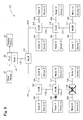
- the PLC communication system 201 corresponds to the portion of the network system illustrated in Fig. 1 , wherein the portion includes the input device 10, PLC 20, display device 30, communication processing node 41 and DeviceNet network 200.
- the node 41 which is a master node of the network, sends data to the other nodes 241 through 248, which are the slave nodes to the master node 41. Then the nodes which received the data from the master node 41 send data to the master node 41. In detail, the master node 41 sends the data to the other nodes 241 through 248 based on the destination address for the data. If the master node 41 cannot send data to a particular slave node, a retrial processing is performed to re-send the data to the particular slave node.
- TCP Transmission Control Protocol
- the network adopts the branched DeviceNet network.
- the nodes 41 and 241 through 248 are connected for data transmission through the HUBs 211 through 218 as the branch taps and the lines 221 through 236.
- Each node 241 through 248 is connected to the respective devices 251 through 258.
- the PLC 20 recognizes the retrial processing causing portions as the routes in communication failure state when the number of retrial processing is equal to or more than a set value.
- the PLC 20 recognizes the route connecting the master node 41 which is the sender of the data and the slave node which is the node of destination address and the subject node of retrial processing as the route in communication failure state.
- the data communication is performed from the master node 41 to the slave nodes 241 through 248 as time passed.
- the data cannot be sent to the slave node 245 from the master node 41 at the time t4 due to the abnormality (disconnection of the line) in the line 230.
- the retrial processing is performed.
- the retrial processing is performed for the data to the slave node 246 at the time t5. Meanwhile, the data transmission continues until the time t27.
- the display device 30 displays the system as indicated in Fig. 16 .
- the number of times the node became the subject of retrial processing is indicated in parentheses for respective slave nodes 241 through 248.
- the number of retrial processing for the slave node 245 is four (4) and similarly the number of retrial processing for the slave node 246 is three (3). These numbers are indicated in respective slave nodes.
- the number of times of forming the route which became in communication failure state is indicated in the HUBs 211 through 218 and the lines 221 through 236.
- the normal communication routes are excluded in judging whether the portion is in abnormal state or warning state.
- the line 230 and the HUB 216 are displayed as the abnormal portion and the lines 231 and 232 are displayed as the warning portion.
- the other portions are illustrated as the normal portion.
- the DeviceNet network 200 of this embodiment can exhibit the similar effects as the FL-net network 100 of the other embodiments.
- the PLC communication system associated with the invention is characterized in that the system comprises a programmable logic controller (PLC), a plurality of processing devices (150, 250, 251-258), at least three communication processing nodes (41, 140, 240,241-248) provided at the PLC and at the plurality of processing devices respectively to establish communication of the PLC and each of the processing devices and an interconnecting device (HUB) and a plurality of communication lines (120, 220, 121-139, 221-236) for connecting the communication processing nodes with one another to establish data communication among the communication processing nodes.
- the PLC detects a state of communication failure and a display device displays an abnormal portion (114, 128, 230, 216) in a communication route based on the number of occurrences of the state of communication failure in respective interconnecting device and plurality of communication lines.
Landscapes
- Engineering & Computer Science (AREA)
- Signal Processing (AREA)
- Computer Networks & Wireless Communication (AREA)
- Physics & Mathematics (AREA)
- General Physics & Mathematics (AREA)
- Automation & Control Theory (AREA)
- Cardiology (AREA)
- Health & Medical Sciences (AREA)
- Quality & Reliability (AREA)
- General Health & Medical Sciences (AREA)
- Manufacturing & Machinery (AREA)
- General Engineering & Computer Science (AREA)
- Environmental & Geological Engineering (AREA)
- Small-Scale Networks (AREA)
- Programmable Controllers (AREA)
- Maintenance And Management Of Digital Transmission (AREA)
Applications Claiming Priority (1)
| Application Number | Priority Date | Filing Date | Title |
|---|---|---|---|
| JP2013097451A JP6204058B2 (ja) | 2013-05-07 | 2013-05-07 | Plc通信システム |
Publications (3)
| Publication Number | Publication Date |
|---|---|
| EP2801877A2 true EP2801877A2 (de) | 2014-11-12 |
| EP2801877A3 EP2801877A3 (de) | 2017-07-12 |
| EP2801877B1 EP2801877B1 (de) | 2019-08-07 |
Family
ID=50442419
Family Applications (1)
| Application Number | Title | Priority Date | Filing Date |
|---|---|---|---|
| EP14164139.9A Active EP2801877B1 (de) | 2013-05-07 | 2014-04-10 | PLC-Kommunikationssystem |
Country Status (4)
| Country | Link |
|---|---|
| US (1) | US9823641B2 (de) |
| EP (1) | EP2801877B1 (de) |
| JP (1) | JP6204058B2 (de) |
| CN (1) | CN104144074B (de) |
Cited By (4)
| Publication number | Priority date | Publication date | Assignee | Title |
|---|---|---|---|---|
| EP3270543A1 (de) * | 2016-07-12 | 2018-01-17 | Omron Corporation | Informationsverarbeitungsvorrichtung, informationsverarbeitungsprogramm und informationsverarbeitungsverfahren |
| EP3355143A1 (de) * | 2017-01-31 | 2018-08-01 | Omron Corporation | Informationsverarbeitungsvorrichtung, informationsverarbeitungsprogramm und informationsverarbeitungsverfahren |
| EP3477406A4 (de) * | 2016-06-24 | 2019-07-31 | Mitsubishi Electric Corporation | Autonomes steuerungssystem zur anlagenüberwachung |
| EP3561623A1 (de) * | 2018-03-26 | 2019-10-30 | OMRON Corporation | Netzwerkverwaltungsvorrichtung, verwaltungsverfahren, verwaltungsprogramm und aufzeichnungsmedium |
Families Citing this family (8)
| Publication number | Priority date | Publication date | Assignee | Title |
|---|---|---|---|---|
| JP6281175B2 (ja) * | 2012-12-07 | 2018-02-21 | 株式会社ジェイテクト | Plc通信システム |
| JP6204058B2 (ja) * | 2013-05-07 | 2017-09-27 | 株式会社ジェイテクト | Plc通信システム |
| JP6264131B2 (ja) * | 2014-03-24 | 2018-01-24 | 住友電気工業株式会社 | 太陽光発電用監視システム及びその通信方法 |
| JP6578899B2 (ja) * | 2015-11-13 | 2019-09-25 | 株式会社ジェイテクト | 通信システムおよび通信ネットワークの情報生成方法 |
| KR20170114643A (ko) * | 2016-04-05 | 2017-10-16 | 엘에스산전 주식회사 | Plc용 통신 시스템 |
| JP7375360B2 (ja) * | 2019-08-02 | 2023-11-08 | オムロン株式会社 | ネットワークシステム、情報処理装置、および情報処理方法 |
| CN116382241A (zh) * | 2023-04-13 | 2023-07-04 | 重庆钢铁股份有限公司 | 一种plc点位非连续性故障的检测方法 |
| US12355646B2 (en) | 2023-11-29 | 2025-07-08 | Wells Fargo Bank, N.A. | Distributed ledger for application health monitoring |
Citations (2)
| Publication number | Priority date | Publication date | Assignee | Title |
|---|---|---|---|---|
| JPH02235104A (ja) | 1989-03-09 | 1990-09-18 | Omron Tateisi Electron Co | プログラマブル・コントローラ |
| JPH06324723A (ja) | 1993-05-14 | 1994-11-25 | Sharp Corp | プログラマブルコントローラ |
Family Cites Families (22)
| Publication number | Priority date | Publication date | Assignee | Title |
|---|---|---|---|---|
| JP2825630B2 (ja) * | 1990-09-07 | 1998-11-18 | 株式会社日立製作所 | 回線切替方式 |
| US5390326A (en) * | 1993-04-30 | 1995-02-14 | The Foxboro Company | Local area network with fault detection and recovery |
| JPH08320713A (ja) * | 1995-05-24 | 1996-12-03 | Fanuc Ltd | 数値制御装置 |
| JP2000101490A (ja) | 1998-09-18 | 2000-04-07 | Daiden Co Ltd | ローカルエリアネットワーク信号状態検出装置 |
| JP3653660B2 (ja) * | 1999-01-11 | 2005-06-02 | 富士通株式会社 | ネットワーク管理方法及びネットワーク管理システム |
| JP2002101490A (ja) | 2000-09-20 | 2002-04-05 | Atex Corp | 立体音響を聞くことができるヘッドフォンシステム |
| US7388872B2 (en) * | 2001-04-06 | 2008-06-17 | Montgomery Jr Charles D | Dynamic communication channel allocation method and system |
| US7337234B2 (en) * | 2002-04-05 | 2008-02-26 | Oracle International Corporation | Retry technique for multi-tier network communication systems |
| US20040158780A1 (en) * | 2003-02-11 | 2004-08-12 | Conrad Jeffrey Richard | Method and system for presenting neighbors of a device in a network via a graphical user interface |
| US20040155899A1 (en) * | 2003-02-11 | 2004-08-12 | Conrad Jeffrey Richard | Method and system for presenting an arrangement of management devices operable in a managed network |
| JP2005031928A (ja) * | 2003-07-11 | 2005-02-03 | Hitachi Ltd | 記憶システム及び記憶システムの障害特定方法 |
| US7166930B2 (en) * | 2003-07-21 | 2007-01-23 | Eaton Power Quality Corporation | Uninterruptible power supply apparatus and methods using a display with variable backlighting |
| US7512841B2 (en) * | 2004-10-22 | 2009-03-31 | Hewlett-Packard Development Company, L.P. | Method and system for network fault analysis |
| US7444186B2 (en) * | 2005-03-01 | 2008-10-28 | Omron Corporation | Programmable controller system |
| JP4461485B2 (ja) * | 2005-04-05 | 2010-05-12 | 株式会社ジェイテクト | 分散制御装置 |
| JP4412322B2 (ja) * | 2006-12-26 | 2010-02-10 | ソニー株式会社 | 通信システム及びその障害検出用の情報の提供方法 |
| JP5088957B2 (ja) * | 2008-02-18 | 2012-12-05 | パナソニック株式会社 | 電力線通信装置、電力線通信システム、および登録処理方法 |
| JP5071151B2 (ja) * | 2008-02-27 | 2012-11-14 | トヨタ自動車株式会社 | 通信システム、その異常推定方法、及び情報読出装置 |
| US9658271B2 (en) * | 2008-09-11 | 2017-05-23 | The Boeing Company | Wire fault illumination and display |
| WO2010143607A1 (ja) * | 2009-06-08 | 2010-12-16 | 日本電気株式会社 | 通信ネットワーク管理システム、方法、及び管理計算機 |
| KR101582695B1 (ko) * | 2010-01-18 | 2016-01-06 | 엘에스산전 주식회사 | 이더넷 기반 전력기기의 통신오류 감시 시스템 및 그 방법 |
| JP6204058B2 (ja) * | 2013-05-07 | 2017-09-27 | 株式会社ジェイテクト | Plc通信システム |
-
2013
- 2013-05-07 JP JP2013097451A patent/JP6204058B2/ja active Active
-
2014
- 2014-04-02 US US14/243,159 patent/US9823641B2/en active Active
- 2014-04-10 EP EP14164139.9A patent/EP2801877B1/de active Active
- 2014-04-25 CN CN201410171905.5A patent/CN104144074B/zh active Active
Patent Citations (2)
| Publication number | Priority date | Publication date | Assignee | Title |
|---|---|---|---|---|
| JPH02235104A (ja) | 1989-03-09 | 1990-09-18 | Omron Tateisi Electron Co | プログラマブル・コントローラ |
| JPH06324723A (ja) | 1993-05-14 | 1994-11-25 | Sharp Corp | プログラマブルコントローラ |
Cited By (7)
| Publication number | Priority date | Publication date | Assignee | Title |
|---|---|---|---|---|
| EP3477406A4 (de) * | 2016-06-24 | 2019-07-31 | Mitsubishi Electric Corporation | Autonomes steuerungssystem zur anlagenüberwachung |
| US11144026B2 (en) | 2016-06-24 | 2021-10-12 | Mitsubishi Electric Corporation | Plant-monitoring autonomous control system |
| EP3270543A1 (de) * | 2016-07-12 | 2018-01-17 | Omron Corporation | Informationsverarbeitungsvorrichtung, informationsverarbeitungsprogramm und informationsverarbeitungsverfahren |
| EP3355143A1 (de) * | 2017-01-31 | 2018-08-01 | Omron Corporation | Informationsverarbeitungsvorrichtung, informationsverarbeitungsprogramm und informationsverarbeitungsverfahren |
| CN108377255A (zh) * | 2017-01-31 | 2018-08-07 | 欧姆龙株式会社 | 信息处理装置、信息处理方法和记录介质 |
| US10491456B2 (en) | 2017-01-31 | 2019-11-26 | Omron Corporation | Information processing device, information processing program, and information processing method |
| EP3561623A1 (de) * | 2018-03-26 | 2019-10-30 | OMRON Corporation | Netzwerkverwaltungsvorrichtung, verwaltungsverfahren, verwaltungsprogramm und aufzeichnungsmedium |
Also Published As
| Publication number | Publication date |
|---|---|
| CN104144074B (zh) | 2019-01-01 |
| CN104144074A (zh) | 2014-11-12 |
| EP2801877B1 (de) | 2019-08-07 |
| US9823641B2 (en) | 2017-11-21 |
| EP2801877A3 (de) | 2017-07-12 |
| JP2014219774A (ja) | 2014-11-20 |
| US20140336784A1 (en) | 2014-11-13 |
| JP6204058B2 (ja) | 2017-09-27 |
Similar Documents
| Publication | Publication Date | Title |
|---|---|---|
| EP2801877B1 (de) | PLC-Kommunikationssystem | |
| JP5229343B2 (ja) | 接続異常検出方法、ネットワークシステムおよびマスター装置 | |
| EP2816428B1 (de) | Steuervorrichtung und steuerverfahren | |
| US10649820B2 (en) | Method of managing event generation for an industrial controller | |
| CN102484606A (zh) | 通信系统及通信装置状态判定方法 | |
| US9170569B2 (en) | Method for electing an active master device from two redundant master devices | |
| JP6281175B2 (ja) | Plc通信システム | |
| CN110995889A (zh) | 地址分配系统和方法 | |
| US20210064004A1 (en) | Control Device, Control Method, and Control Program | |
| JP6578899B2 (ja) | 通信システムおよび通信ネットワークの情報生成方法 | |
| CN104781792B (zh) | 判断在工业控制系统中的故障的冗余设备单元和方法,工业控制系统和包括冗余设备单元的工业系统 | |
| CN104426793A (zh) | 用于控制网络信息流通量的装置 | |
| US9871616B2 (en) | Error detection and recovery in a DMX512 network | |
| CN105934720A (zh) | 可编程控制器以及可编程控制器系统 | |
| CN108983695A (zh) | 一种基于复杂可编程逻辑器件的主从切换方法和装置 | |
| EP3311275B1 (de) | Steuerungssystem mit fehlererkennung | |
| RU2546574C1 (ru) | Арбитр интерфейса rs-485 | |
| CN102340781B (zh) | 用于运行自动化网络的方法 | |
| CN113328917A (zh) | 用于epa链路诊断的方法、epa设备和计算机存储介质 | |
| JP2005267398A (ja) | Plc間通信システムおよびその伝送異常検出方法 | |
| CN104483926A (zh) | 一种主控单元分布式控制方法 | |
| KR20150025759A (ko) | 스니핑 기반의 plc 제어 시스템 | |
| KR20140089113A (ko) | 우선순위 기반의 무선 통신 장치 | |
| JP2019022167A (ja) | 通信装置および通信システム | |
| RU193222U1 (ru) | Модуль контроля и управления технологическими процессами |
Legal Events
| Date | Code | Title | Description |
|---|---|---|---|
| PUAI | Public reference made under article 153(3) epc to a published international application that has entered the european phase |
Free format text: ORIGINAL CODE: 0009012 |
|
| 17P | Request for examination filed |
Effective date: 20140410 |
|
| AK | Designated contracting states |
Kind code of ref document: A2 Designated state(s): AL AT BE BG CH CY CZ DE DK EE ES FI FR GB GR HR HU IE IS IT LI LT LU LV MC MK MT NL NO PL PT RO RS SE SI SK SM TR |
|
| AX | Request for extension of the european patent |
Extension state: BA ME |
|
| PUAL | Search report despatched |
Free format text: ORIGINAL CODE: 0009013 |
|
| AK | Designated contracting states |
Kind code of ref document: A3 Designated state(s): AL AT BE BG CH CY CZ DE DK EE ES FI FR GB GR HR HU IE IS IT LI LT LU LV MC MK MT NL NO PL PT RO RS SE SI SK SM TR |
|
| AX | Request for extension of the european patent |
Extension state: BA ME |
|
| RIC1 | Information provided on ipc code assigned before grant |
Ipc: H04L 12/24 20060101ALI20170602BHEP Ipc: G05B 19/418 20060101AFI20170602BHEP Ipc: H04L 12/403 20060101ALI20170602BHEP Ipc: G05B 19/05 20060101ALI20170602BHEP |
|
| STAA | Information on the status of an ep patent application or granted ep patent |
Free format text: STATUS: REQUEST FOR EXAMINATION WAS MADE |
|
| R17P | Request for examination filed (corrected) |
Effective date: 20171206 |
|
| STAA | Information on the status of an ep patent application or granted ep patent |
Free format text: STATUS: EXAMINATION IS IN PROGRESS |
|
| 17Q | First examination report despatched |
Effective date: 20180308 |
|
| GRAP | Despatch of communication of intention to grant a patent |
Free format text: ORIGINAL CODE: EPIDOSNIGR1 |
|
| STAA | Information on the status of an ep patent application or granted ep patent |
Free format text: STATUS: GRANT OF PATENT IS INTENDED |
|
| INTG | Intention to grant announced |
Effective date: 20190221 |
|
| RAP1 | Party data changed (applicant data changed or rights of an application transferred) |
Owner name: JTEKT CORPORATION Owner name: TOYOTA JIDOSHA KABUSHIKI KAISHA |
|
| GRAS | Grant fee paid |
Free format text: ORIGINAL CODE: EPIDOSNIGR3 |
|
| GRAA | (expected) grant |
Free format text: ORIGINAL CODE: 0009210 |
|
| STAA | Information on the status of an ep patent application or granted ep patent |
Free format text: STATUS: THE PATENT HAS BEEN GRANTED |
|
| AK | Designated contracting states |
Kind code of ref document: B1 Designated state(s): AL AT BE BG CH CY CZ DE DK EE ES FI FR GB GR HR HU IE IS IT LI LT LU LV MC MK MT NL NO PL PT RO RS SE SI SK SM TR |
|
| REG | Reference to a national code |
Ref country code: GB Ref legal event code: FG4D |
|
| REG | Reference to a national code |
Ref country code: CH Ref legal event code: EP Ref country code: AT Ref legal event code: REF Ref document number: 1164799 Country of ref document: AT Kind code of ref document: T Effective date: 20190815 |
|
| REG | Reference to a national code |
Ref country code: DE Ref legal event code: R096 Ref document number: 602014051145 Country of ref document: DE |
|
| REG | Reference to a national code |
Ref country code: IE Ref legal event code: FG4D |
|
| REG | Reference to a national code |
Ref country code: NL Ref legal event code: MP Effective date: 20190807 |
|
| REG | Reference to a national code |
Ref country code: LT Ref legal event code: MG4D |
|
| PG25 | Lapsed in a contracting state [announced via postgrant information from national office to epo] |
Ref country code: NO Free format text: LAPSE BECAUSE OF FAILURE TO SUBMIT A TRANSLATION OF THE DESCRIPTION OR TO PAY THE FEE WITHIN THE PRESCRIBED TIME-LIMIT Effective date: 20191107 Ref country code: FI Free format text: LAPSE BECAUSE OF FAILURE TO SUBMIT A TRANSLATION OF THE DESCRIPTION OR TO PAY THE FEE WITHIN THE PRESCRIBED TIME-LIMIT Effective date: 20190807 Ref country code: HR Free format text: LAPSE BECAUSE OF FAILURE TO SUBMIT A TRANSLATION OF THE DESCRIPTION OR TO PAY THE FEE WITHIN THE PRESCRIBED TIME-LIMIT Effective date: 20190807 Ref country code: LT Free format text: LAPSE BECAUSE OF FAILURE TO SUBMIT A TRANSLATION OF THE DESCRIPTION OR TO PAY THE FEE WITHIN THE PRESCRIBED TIME-LIMIT Effective date: 20190807 Ref country code: SE Free format text: LAPSE BECAUSE OF FAILURE TO SUBMIT A TRANSLATION OF THE DESCRIPTION OR TO PAY THE FEE WITHIN THE PRESCRIBED TIME-LIMIT Effective date: 20190807 Ref country code: BG Free format text: LAPSE BECAUSE OF FAILURE TO SUBMIT A TRANSLATION OF THE DESCRIPTION OR TO PAY THE FEE WITHIN THE PRESCRIBED TIME-LIMIT Effective date: 20191107 Ref country code: NL Free format text: LAPSE BECAUSE OF FAILURE TO SUBMIT A TRANSLATION OF THE DESCRIPTION OR TO PAY THE FEE WITHIN THE PRESCRIBED TIME-LIMIT Effective date: 20190807 Ref country code: PT Free format text: LAPSE BECAUSE OF FAILURE TO SUBMIT A TRANSLATION OF THE DESCRIPTION OR TO PAY THE FEE WITHIN THE PRESCRIBED TIME-LIMIT Effective date: 20191209 |
|
| REG | Reference to a national code |
Ref country code: AT Ref legal event code: MK05 Ref document number: 1164799 Country of ref document: AT Kind code of ref document: T Effective date: 20190807 |
|
| PG25 | Lapsed in a contracting state [announced via postgrant information from national office to epo] |
Ref country code: GR Free format text: LAPSE BECAUSE OF FAILURE TO SUBMIT A TRANSLATION OF THE DESCRIPTION OR TO PAY THE FEE WITHIN THE PRESCRIBED TIME-LIMIT Effective date: 20191108 Ref country code: LV Free format text: LAPSE BECAUSE OF FAILURE TO SUBMIT A TRANSLATION OF THE DESCRIPTION OR TO PAY THE FEE WITHIN THE PRESCRIBED TIME-LIMIT Effective date: 20190807 Ref country code: AL Free format text: LAPSE BECAUSE OF FAILURE TO SUBMIT A TRANSLATION OF THE DESCRIPTION OR TO PAY THE FEE WITHIN THE PRESCRIBED TIME-LIMIT Effective date: 20190807 Ref country code: RS Free format text: LAPSE BECAUSE OF FAILURE TO SUBMIT A TRANSLATION OF THE DESCRIPTION OR TO PAY THE FEE WITHIN THE PRESCRIBED TIME-LIMIT Effective date: 20190807 Ref country code: IS Free format text: LAPSE BECAUSE OF FAILURE TO SUBMIT A TRANSLATION OF THE DESCRIPTION OR TO PAY THE FEE WITHIN THE PRESCRIBED TIME-LIMIT Effective date: 20191207 Ref country code: ES Free format text: LAPSE BECAUSE OF FAILURE TO SUBMIT A TRANSLATION OF THE DESCRIPTION OR TO PAY THE FEE WITHIN THE PRESCRIBED TIME-LIMIT Effective date: 20190807 |
|
| PG25 | Lapsed in a contracting state [announced via postgrant information from national office to epo] |
Ref country code: TR Free format text: LAPSE BECAUSE OF FAILURE TO SUBMIT A TRANSLATION OF THE DESCRIPTION OR TO PAY THE FEE WITHIN THE PRESCRIBED TIME-LIMIT Effective date: 20190807 |
|
| PG25 | Lapsed in a contracting state [announced via postgrant information from national office to epo] |
Ref country code: RO Free format text: LAPSE BECAUSE OF FAILURE TO SUBMIT A TRANSLATION OF THE DESCRIPTION OR TO PAY THE FEE WITHIN THE PRESCRIBED TIME-LIMIT Effective date: 20190807 Ref country code: IT Free format text: LAPSE BECAUSE OF FAILURE TO SUBMIT A TRANSLATION OF THE DESCRIPTION OR TO PAY THE FEE WITHIN THE PRESCRIBED TIME-LIMIT Effective date: 20190807 Ref country code: PL Free format text: LAPSE BECAUSE OF FAILURE TO SUBMIT A TRANSLATION OF THE DESCRIPTION OR TO PAY THE FEE WITHIN THE PRESCRIBED TIME-LIMIT Effective date: 20190807 Ref country code: AT Free format text: LAPSE BECAUSE OF FAILURE TO SUBMIT A TRANSLATION OF THE DESCRIPTION OR TO PAY THE FEE WITHIN THE PRESCRIBED TIME-LIMIT Effective date: 20190807 Ref country code: DK Free format text: LAPSE BECAUSE OF FAILURE TO SUBMIT A TRANSLATION OF THE DESCRIPTION OR TO PAY THE FEE WITHIN THE PRESCRIBED TIME-LIMIT Effective date: 20190807 Ref country code: EE Free format text: LAPSE BECAUSE OF FAILURE TO SUBMIT A TRANSLATION OF THE DESCRIPTION OR TO PAY THE FEE WITHIN THE PRESCRIBED TIME-LIMIT Effective date: 20190807 |
|
| PG25 | Lapsed in a contracting state [announced via postgrant information from national office to epo] |
Ref country code: CZ Free format text: LAPSE BECAUSE OF FAILURE TO SUBMIT A TRANSLATION OF THE DESCRIPTION OR TO PAY THE FEE WITHIN THE PRESCRIBED TIME-LIMIT Effective date: 20190807 Ref country code: IS Free format text: LAPSE BECAUSE OF FAILURE TO SUBMIT A TRANSLATION OF THE DESCRIPTION OR TO PAY THE FEE WITHIN THE PRESCRIBED TIME-LIMIT Effective date: 20200224 Ref country code: SM Free format text: LAPSE BECAUSE OF FAILURE TO SUBMIT A TRANSLATION OF THE DESCRIPTION OR TO PAY THE FEE WITHIN THE PRESCRIBED TIME-LIMIT Effective date: 20190807 Ref country code: SK Free format text: LAPSE BECAUSE OF FAILURE TO SUBMIT A TRANSLATION OF THE DESCRIPTION OR TO PAY THE FEE WITHIN THE PRESCRIBED TIME-LIMIT Effective date: 20190807 |
|
| REG | Reference to a national code |
Ref country code: DE Ref legal event code: R097 Ref document number: 602014051145 Country of ref document: DE |
|
| PLBE | No opposition filed within time limit |
Free format text: ORIGINAL CODE: 0009261 |
|
| STAA | Information on the status of an ep patent application or granted ep patent |
Free format text: STATUS: NO OPPOSITION FILED WITHIN TIME LIMIT |
|
| PG2D | Information on lapse in contracting state deleted |
Ref country code: IS |
|
| 26N | No opposition filed |
Effective date: 20200603 |
|
| PG25 | Lapsed in a contracting state [announced via postgrant information from national office to epo] |
Ref country code: SI Free format text: LAPSE BECAUSE OF FAILURE TO SUBMIT A TRANSLATION OF THE DESCRIPTION OR TO PAY THE FEE WITHIN THE PRESCRIBED TIME-LIMIT Effective date: 20190807 |
|
| PG25 | Lapsed in a contracting state [announced via postgrant information from national office to epo] |
Ref country code: MC Free format text: LAPSE BECAUSE OF FAILURE TO SUBMIT A TRANSLATION OF THE DESCRIPTION OR TO PAY THE FEE WITHIN THE PRESCRIBED TIME-LIMIT Effective date: 20190807 |
|
| REG | Reference to a national code |
Ref country code: CH Ref legal event code: PL |
|
| PG25 | Lapsed in a contracting state [announced via postgrant information from national office to epo] |
Ref country code: CH Free format text: LAPSE BECAUSE OF NON-PAYMENT OF DUE FEES Effective date: 20200430 Ref country code: LI Free format text: LAPSE BECAUSE OF NON-PAYMENT OF DUE FEES Effective date: 20200430 Ref country code: FR Free format text: LAPSE BECAUSE OF NON-PAYMENT OF DUE FEES Effective date: 20200430 Ref country code: LU Free format text: LAPSE BECAUSE OF NON-PAYMENT OF DUE FEES Effective date: 20200410 |
|
| REG | Reference to a national code |
Ref country code: BE Ref legal event code: MM Effective date: 20200430 |
|
| PG25 | Lapsed in a contracting state [announced via postgrant information from national office to epo] |
Ref country code: BE Free format text: LAPSE BECAUSE OF NON-PAYMENT OF DUE FEES Effective date: 20200430 |
|
| GBPC | Gb: european patent ceased through non-payment of renewal fee |
Effective date: 20200410 |
|
| PG25 | Lapsed in a contracting state [announced via postgrant information from national office to epo] |
Ref country code: IE Free format text: LAPSE BECAUSE OF NON-PAYMENT OF DUE FEES Effective date: 20200410 Ref country code: GB Free format text: LAPSE BECAUSE OF NON-PAYMENT OF DUE FEES Effective date: 20200410 |
|
| PG25 | Lapsed in a contracting state [announced via postgrant information from national office to epo] |
Ref country code: MT Free format text: LAPSE BECAUSE OF FAILURE TO SUBMIT A TRANSLATION OF THE DESCRIPTION OR TO PAY THE FEE WITHIN THE PRESCRIBED TIME-LIMIT Effective date: 20190807 Ref country code: CY Free format text: LAPSE BECAUSE OF FAILURE TO SUBMIT A TRANSLATION OF THE DESCRIPTION OR TO PAY THE FEE WITHIN THE PRESCRIBED TIME-LIMIT Effective date: 20190807 |
|
| PG25 | Lapsed in a contracting state [announced via postgrant information from national office to epo] |
Ref country code: MK Free format text: LAPSE BECAUSE OF FAILURE TO SUBMIT A TRANSLATION OF THE DESCRIPTION OR TO PAY THE FEE WITHIN THE PRESCRIBED TIME-LIMIT Effective date: 20190807 |
|
| PGFP | Annual fee paid to national office [announced via postgrant information from national office to epo] |
Ref country code: DE Payment date: 20250305 Year of fee payment: 12 |