EP2802053A1 - Système de stabilisation de réseau électrique et procédé de stabilisation de réseau électrique - Google Patents
Système de stabilisation de réseau électrique et procédé de stabilisation de réseau électrique Download PDFInfo
- Publication number
- EP2802053A1 EP2802053A1 EP12864565.2A EP12864565A EP2802053A1 EP 2802053 A1 EP2802053 A1 EP 2802053A1 EP 12864565 A EP12864565 A EP 12864565A EP 2802053 A1 EP2802053 A1 EP 2802053A1
- Authority
- EP
- European Patent Office
- Prior art keywords
- power storage
- power
- compensation operation
- storage systems
- information
- Prior art date
- Legal status (The legal status is an assumption and is not a legal conclusion. Google has not performed a legal analysis and makes no representation as to the accuracy of the status listed.)
- Withdrawn
Links
Images





Classifications
-
- G—PHYSICS
- G05—CONTROLLING; REGULATING
- G05F—SYSTEMS FOR REGULATING ELECTRIC OR MAGNETIC VARIABLES
- G05F1/00—Automatic systems in which deviations of an electric quantity from one or more predetermined values are detected at the output of the system and fed back to a device within the system to restore the detected quantity to its predetermined value or values, i.e. retroactive systems
- G05F1/66—Regulating electric power
-
- H—ELECTRICITY
- H02—GENERATION; CONVERSION OR DISTRIBUTION OF ELECTRIC POWER
- H02J—ELECTRIC POWER NETWORKS; CIRCUIT ARRANGEMENTS OR SYSTEMS FOR SUPPLYING OR DISTRIBUTING ELECTRIC POWER; SYSTEMS FOR STORING ELECTRIC ENERGY
- H02J3/00—Circuit arrangements for AC mains or AC distribution networks
- H02J3/28—Arrangements for balancing of the load in networks by storage of energy
- H02J3/32—Arrangements for balancing of the load in networks by storage of energy using batteries or super capacitors with converting means
-
- H—ELECTRICITY
- H02—GENERATION; CONVERSION OR DISTRIBUTION OF ELECTRIC POWER
- H02J—ELECTRIC POWER NETWORKS; CIRCUIT ARRANGEMENTS OR SYSTEMS FOR SUPPLYING OR DISTRIBUTING ELECTRIC POWER; SYSTEMS FOR STORING ELECTRIC ENERGY
- H02J3/00—Circuit arrangements for AC mains or AC distribution networks
- H02J3/38—Arrangements for feeding a single network from two or more generators or sources in parallel; Arrangements for feeding already energised networks from additional generators or sources in parallel
- H02J3/381—Dispersed generators
-
- H—ELECTRICITY
- H02—GENERATION; CONVERSION OR DISTRIBUTION OF ELECTRIC POWER
- H02J—ELECTRIC POWER NETWORKS; CIRCUIT ARRANGEMENTS OR SYSTEMS FOR SUPPLYING OR DISTRIBUTING ELECTRIC POWER; SYSTEMS FOR STORING ELECTRIC ENERGY
- H02J3/00—Circuit arrangements for AC mains or AC distribution networks
- H02J3/38—Arrangements for feeding a single network from two or more generators or sources in parallel; Arrangements for feeding already energised networks from additional generators or sources in parallel
- H02J3/46—Controlling the sharing of generated power between the generators, sources or networks
-
- H—ELECTRICITY
- H02—GENERATION; CONVERSION OR DISTRIBUTION OF ELECTRIC POWER
- H02J—ELECTRIC POWER NETWORKS; CIRCUIT ARRANGEMENTS OR SYSTEMS FOR SUPPLYING OR DISTRIBUTING ELECTRIC POWER; SYSTEMS FOR STORING ELECTRIC ENERGY
- H02J2101/00—Supply or distribution of decentralised, dispersed or local electric power generation
- H02J2101/20—Dispersed power generation using renewable energy sources
Definitions
- the present invention relates to a power system stabilization system and a power system stabilization method.
- PV solar photovoltaic generation
- wind-power generation wind-power generation
- the typical renewable energies mentioned above are dispersed power sources, and they are generally unstable in output compared with conventional thermal power generation or hydraulic power generation. Therefore, in cases where dispersed power sources are connected to a power system, a technical measure for dealing with sharp output variations is required.
- Patent Literature 1 a configuration in which the output variations of dispersed power sources are suppressed using NAS (sodium-sulfur) batteries and capacitors is partly disclosed (Patent Literature 1).
- Patent Literature 2 a configuration is disclosed in which a secondary battery for peak power smoothing is connected with a capacitor in parallel for complementing between charging and discharging of the secondary battery (Patent Literature 2).
- An object of the present invention is to provide a power system stabilization system and a power system stabilization method for appropriately suppressing disturbances occurring in a power system by using plural power storage systems.
- the power system stabilization system of the present invention that is a system for stabilizing a power system includes a plurality of power storage systems provided in a power system and a management system connected, via a communication network, to the plurality of power storage systems.
- the plurality of power storage systems each include a power storage device and a control device for controlling the power storage device
- the control device includes a storage unit for storing performance information about the power storage system including the control device, location information indicating a location in the power system of the power storage system including the control device, and order information indicating an order of operation allocated, for each disturbance location, to the power storage system including the control device, and a compensation operation control unit which performs, when a disturbance occurs in the power system, a predetermined compensation operation based on the location information and the order information.
- the plurality of power storage systems may be grouped beforehand according to predetermined districts set for the power system.
- the storage units of those power storage systems, among the plurality of power storage systems, belonging to a same group share the location information and the order information.
- the compensation operation control units of the power storage systems belonging to a same group each perform the predetermined compensation operation according to the order of operation indicated by the order information.
- each of the compensation operation control units may obtain, from the management system, information indicating whether or not the order of operation specified in the order information has arrived and, when the order of operation is determined to have arrived, may perform the predetermined compensation operation.
- At least a part of the present invention can be realized as a computer program or a hardware circuit.
- the computer program can be distributed using a communication medium like the Internet or using a recording medium such as a hard disk or a flash memory device.
- plural power storage systems distributed in power system share location information indicating their locations in the power system and order information indicating an order in which they operate.
- the plural power storage systems can collaboratively perform compensation operations in the order specified by the order information.
- Each of the plural power storage systems has identification information indicating its order number in the power storage system.
- the order of operation of each power storage system is preset. The order of operations is determined such that the power storage systems closer to the location of a disturbance operate earlier. The power storage systems farther from the location of a disturbance are lower in the order of operations. Note that the closeness to or farness from a disturbance location is determined based on the routing of power lines.
- FIG. 1 shows a power system configuration including a power system stabilization system 1 according to a first embodiment of the present invention.
- a substation 2 which transforms the power received from a large-scale centralized power station into a predetermined voltage and distributes the transformed power is connected with a transmission line 3 from which plural distribution lines 4A and 4B are branched.
- the distribution lines 4A and 4B will be each referred to as a "distribution line 4.”
- the transmission line 3 or distribution lines 4 are connected with power storage systems 10 and 50.
- the power storage system 10 is an object of control in the present embodiment.
- the other power storage system 50 is not an object of control in the present embodiment. It is shown for comparison purposes. The configuration of the power storage system 10 will be described later.
- a dispersed power source 20 is connected to the transmission line 3 or distribution line 4.
- the dispersed power source 20 includes, for example, a solar photovoltaic system 21 or a wind power station 22.
- the dispersed power source 20 is not limited to a solar photovoltaic system or a wind power station. It may be, for example, a solar thermal power system.
- Loads 30(1) and 30(2) are various electrical loads held by users.
- the load 30(1) is, for example, a load of a relatively large capacity such as a large electric motor.
- the power storage system 10 can recognize starting and stopping of the large-scale load 30(1).
- the load 30(1) to be monitored by the power storage system 10 is not limited to one.
- the power storage system 10 can remotely monitor startings and stoppings of plural loads 30(1).
- the other load 30(2) is, for example, a general household electrical product, an air conditioner for building, an illumination device, or a passenger conveyor.
- the loads 30(1) and 30(2) will be each referred to as a "load 30.”
- a detector 40 detects condition process quantities of the power system and transmits detected signals to the power storage system 10.
- the condition process quantities of the power system include frequencies, phases and voltages.
- the detector 40 may be configured like, for example, an instrument voltage transformer (VT) or an instrument current transformer (CT). Even though only one detector 40 is shown in the figure, plural detectors 40 may be connected to the power storage system 10. Note that, even though the power system includes plural switches and voltage regulators, their illustrations are omitted in describing the present embodiment.
- Each power storage system 10 includes, for example, a power storage device (11, 12) and a control device 100.
- the power storage system 10 is bidirectionally communicatably connected to a management system 60 via a communication network CN1.
- the power storage device (11, 12) includes, for example, a capacitor 11 and a storage battery 12.
- the capacitor 11 may be configured like, for example, a lithium ion capacitor. It may also be configured like an alternative type of capacitor such as an electric double layer capacitor.
- the capacitor 11 is higher in responsiveness than the storage battery and can instantaneously charge or discharge large power.
- the storage battery 12 is configured like, for example, a lead storage battery, a lithium ion secondary battery, a nickel-hydrogen secondary battery, or a sodium-sulfur secondary battery (NAS battery: registered trademark).
- the storage battery 12 is low in responsiveness compared with the capacitor 11, but it can charge and discharge power over a relatively long period of time. Namely, the storage battery 12 can be configured to be larger in a total chargeable/dischargeable amount of energy than the capacitor 11.
- the power storage device (11, 12) will also be referred to simply as a power storage device without any reference numeral.
- the power storage device includes the capacitor 11 and the storage battery 12 that, as described above, differ from each other in charging/discharging characteristics.
- the control device 100 uses either the capacitor 11 or the storage battery 12 depending on the compensation operation to be performed. For example, the control device 100 has the capacitor 11 perform charging/discharging to deal with sharply varying transient responses or has the storage battery 12 perform charging/discharging to deal with prolonged variations.
- the charge/discharge performance of the capacitor 11 and the storage battery 12 does not particularly matter.
- the control device 100 is a device for, when a disturbance occurs in the power system, causing a predetermined compensation operation to be performed to suppress the disturbance and stabilize the power system.
- the control device 100 includes, for example, a microprocessor (shown as "CPU” (Central processing Unit) in the figure) 110, a storage unit 120, an input/output unit (shown as “I/O” in the figure) 130, and a communication interface unit (shown as "I/F” in the figure) 140. These circuits 110 to 140 are connected to a bus 150.
- the storage unit 120 may be configured to include, for example, a ROM (Read Only Memory), a RAM (Random Access Memory), a hard disk device, and a flash memory device.
- the storage unit 120 stores, in addition to a basic program such as an operating system (not shown), computer programs for realizing a charge/discharge control unit P10 and an information setting unit P20.
- the microprocessor 110 realizes the functions being described later by executing computer programs read from the storage unit 120.
- the storage unit 120 stores, for example, unique identification information T10 and basic system information. T11. Also, the storage unit 120 can store topology information being described later with reference to FIG. 4 . Furthermore, the storage unit 120 can also store schedule control information T12 being described later with reference to FIG. 5 .
- the input/output unit 130 is a circuit for exchanging signals with, for example, the power storage device (11, 12), the detector 40, and the specific load 30(1).
- the communication interface unit 140 is a circuit for communicating with the management system 60 via the communication network CN1.
- the management system 60 manages compensation operations of plural power storage systems 10.
- the management system 60 holds the basic system information T11.
- the management system 60 maybe configured, for example, as a part of a power feed instruction center.
- the power feed instruction center is a control system managed by a business operator managing the power system.
- the management system 60 may be configured as a system different from the power feed instruction center or may be configured in one of the plural power storage systems 10 so as to provide the power storage system 10 with the function of the management system 60.
- the management system 60 may be configured with one computer or may be configured by having plural computers operate in collaboration.
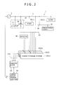
- FIG. 2 shows connections for communication between the management system 60 and plural power storage systems 10(1), 10(2), and 10(3).
- the power storage systems 10(1) to 10(3) will be each referred to as a "power storage system 10.”
- Each power storage system 10 is connected to the management system 60 via the communication network CN1. Each power storage system 10 is also connected to the detector 40. Furthermore, each power storage system 10 is also connected to the load 30(1) that is an object of monitoring.
- the management system 60 can also communicate with a large-scale power station (centralized power station), for example, a thermal power station.
- the management system 60 can control, in collaboration with the operation of the large-scale power station 70, the compensation operation performed by each power storage system 10.
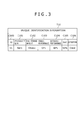
- FIG. 3 shows an example of composition of the unique identification information T10.
- the unique identification information T10 is information for identifying an individual power storage system 10 and includes performance information about a power storage device.
- the unique identification information T10 associatively manages, for example, a system identifier C100, a product serial number C101, a maximum storage amount C102, charge performance C103, discharge performance C104, a remaining power amount (SoC: State of Charge) C105, and condition C106.
- SoC State of Charge
- the system identifier C100 is for identifying a power storage system 10 managed by the management system 60.
- the system identifier C100 can be made corresponding to the location where a power storage system 10 is installed. When the system identifier is known, where in the power system the power storage system 10 is located can be known.
- the product serial number C101 indicates the product serial number of the power storage system 10.
- the maximum storage amount C102 indicates the maximum amount of power that can be stored in the power storage device.
- the charge performance C103 indicates the charge performance of the power storage device.
- the discharge performance C104 indicates the discharge performance of the power storage device.
- the remaining power amount C105 indicates the amount of power remaining in the power storage device. This is indicated without distinguishing the capacitor 11 and the storage battery 12. In reality, the performance of each of the capacitor 11 and the storage battery 12 is managed separately.
- the condition C106 indicates the condition of the power storage system 10.
- the condition may be normal, faulty, or stopped.
- Information not indicated in FIG. 3 for example, a producer name, a production date, and version information can also be managed in the unique identification information T10.
- FIG. 4 shows an example of composition of the basic system information T11.
- the basic system information T11 manages, regarding the power storage systems 10 in the power system, their locations, their conditions, the groups they belong to, their orders of operations, and their schedules.
- the basic system information T11 includes, for example, management numbers C110, system identifiers C111, product serial numbers and additional information C112, presence flags C113, operability flags C114, topology confirmation flags C115, group numbers C116, orders of operations C117, and schedule control C118.
- the management numbers C110 are consecutive row numbers.
- the system identifiers C111 identify the power storage systems 10, respectively. They include the identifier C100 described with reference to FIG. 3 .
- the product serial numbers and additional information C112 include the product serial number and information about the charge/discharge performance of each power storage system 10.
- the presence flags C113 indicate whether or not the power storage systems 10 are currently present, respectively. For each power storage system 10, this flag is set to "1" when the system is present or set to "0" when the system is not present. For example, when a power storage system 10 is removed, the corresponding presence flag is set to "0.”
- the operability flags C114 indicate whether or not the power storage systems 10 are currently operable, respectively. For each power storage system 10, this flag is set to "1" when the system is operable or set to "0" when the system is not operable. When a power storage system 10 is operable, it is ready to perform a predetermined compensation operation normally. For example, when a power storage system 10 is deactivated for repair or inspection, the corresponding operability flag C114 is set to "0.” For example, when a power storage system 10 develops a fault, the operability flag C114 for the system is set to "0.”
- the topology confirmation flags C115 indicate whether or not the power storage systems 10 have confirmed and stored topology information on the power system configuration in their storage units 120.
- the topology information is equivalent to the "location information.” It indicates to which parts of which distribution lines each power storage system 10 and the load 30 are connected.
- the topology confirmation flag C115 for the system is set to "1.”
- the topology confirmation flag C115 for the system is set to "0.”
- the group numbers C116 identify the groups to which the power storage systems 10 belong, respectively.
- Each group represents a district predetermined in connection with the power system.
- plural groups can be set by dividing a geographical area associated with the power system into plural districts according to electrical characteristics, for example, "a northern redevelopment district, " "an eastern residential district,” and "a western industrial district.”
- a geographical area can be divided according to locations where transformers, substations, switches, circuit breakers, etc. are installed.
- the orders of operations C117 indicate the orders of compensation operations to be performed by the respective power storage systems 10.
- the orders of operations C117 included in the basic system information T11 are equivalent to the "order information."
- the highest order is represented by order no. "1" and larger order numbers represent lower orders of operations.
- the power storage system 10 allocated with the highest order of operation can immediately start a predetermined compensation operation when a disturbance occurs in the group to which it belongs without waiting for any instruction or notification from the management system 60.
- Each of the remaining power storage systems 10 starts a predetermined compensation operation only after all other power storage systems allocated with smaller order numbers than the order number allocated to itself started compensation operations.
- a disturbance as referred to in the present specification represents a state in which a voltage, frequency or phase variation has exceeded a predetermined threshold. Namely, when a pre-specified condition process quantity exits a specified tolerable range, it is determined that a disturbance has occurred.
- a predetermined compensation operation is an operation to be performed to suppress a disturbance and stabilize the power system.
- the relevant power storage system 10 supplies, as a responsive compensation operation, reactive power from the power storage device to the power system.
- the power storage system 10 operates contrarily to the above as compensation operation.
- the relevant power storage system 10 supplies, in a responsive compensation operation, active power from the power storage device to the power system.
- the relevant power storage system 10 operates contrarily to the above as compensation operation.
- the schedule control C118 is information for identifying the schedule control information T12 set in each power storage system 10.
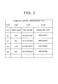
- the schedule control information T12 associatively manages, for example, management numbers C120, target device numbers C121, time and date information C122, and operation types C123.
- the management numbers C120 are consecutive numbers for managing individual schedules.
- the target devices C121 provide information for identifying the power storage element (either the capacitor 11 or the storage battery 12) to operate according to each schedule.
- the time and date information C122 indicates the time and date when each power storage element is to operate.
- the operation types C123 indicate the type of operation (either discharging or charging) to be performed by each power storage element.
- schedule control for suppressing associated load variations is planned.
- Schedule control for suppressing load variations caused by rice cooking is set in each power storage system belonging to the group associated with the residential district.
- the quick-responding capacitor 11 may be made to discharge first to be then followed by the storage battery 12. In this way, such periodic load variations occurring in the residential district can be prevented.
- schedule control for suppressing associated load variations is planned.
- schedule control for suppressing load variations caused by startings and stoppings of electrical devices (production equipment, etc.) at factories is set.
- the quick-responding capacitor 11 may be made to discharge first to be then followed by the storage battery 12. In this way, such periodic load variations occurring in the industrial district can be prevented.
- an area receiving electric power from a power system to be an object of stabilization is divided into plural districts according to electrical characteristics (e.g., according to whether districts require power supply for general households or require high-voltage power supply for industrial use) , and a group is set for each district.
- the power storage systems 10 located in each district are made to belong to the group associated with the district.
- each group corresponds to a district determined as a result of dividing an area receiving electric power from a power system to be an object of stabilization
- periodical load variations related with the electrical characteristics of the district can occur in the group. For example, in a district in which there are many general households, power consumption characteristically increases during evening hours when they cook rice and take a bath, whereas power consumption is relatively small during daytime hours. In a district in which there are many factories, power consumption characteristically varies based on factory work hours.
- schedule control planned based on the characteristics of each district associated with each group is set beforehand in each power storage system 10 belonging to the group. It is, therefore, possible to prevent, in the district associated with each group, periodic load variations and keep the power system stable. Furthermore, in the present embodiment, the order of operation is set beforehand for each power storage system 10 belonging to each group as being described later, and the power storage system 10 allocated with order-of-operation no. 1 can start compensation operation immediately. Therefore, even when an abrupt load variation (disturbance) occurs in a district associated with a group, the load variation caused by the irregularity can be quickly suppressed to stabilize the power system.
- FIG. 6 is a flowchart of processing performed by the management system 60 to set predetermined information in each power storage system 10.
- the manager of the power system stabilization system (e.g., the manager of the power system) can enter predetermined information in each power storage system 10 via the management system 60.
- a case of entering information in a power storage system 10 will be described below.
- Information can be entered in plural power storage systems 10 by repeating the processing shown in FIG. 6 .
- the management system 60 determines whether the target power storage system for information setting is a power storage system 10 to be managed by the management system 60 (S10). This is because the power system possibly includes power storage systems 50 not to be managed by the management system 60.
- the management system 60 excludes the power storage system 50 from the power system stabilization system (S11). Excluding the power storage system 50 from the power system stabilization system is prohibiting, when a disturbance occurs in the power system, the power storage system 50 not to be managed by the management system 60 from performing discharging operation responding to the disturbance.
- the management system 60 requests, using communication means such as an electronic mail, the personnel in charge of managing the power storage system 50 not to allow the power storage system 50 to perform charging/discharging operation responding to occurrence of a disturbance.
- the management system 60 determines whether the power storage system 10 is operable (S12). Namely, the management system 60 determines whether the power storage system 10 is in a normal operable state and also whether the remaining power amount (SoC) of the power storage system 10 is enough for performing compensation operation.
- SoC remaining power amount
- the management system 60 determines that the power storage system 60 is inoperable (S12: NO).
- the management system 60 excludes the power storage system 10 determined to be inoperable from the power system stabilization system (S13).
- the power storage system 10 excluded from the power system stabilization system does not execute, when a disturbance occurs, compensation operation.
- the management system 60 sets, for the power storage system to be excluded, the operability flag C114 included in the basic system information T11 to "0." In the group to which the excluded power storage system belongs, only the remaining operable power storage systems are to deal with occurrence of a disturbance in the power system.
- the management system 60 sets the basic system information T11 and schedule control information T12 in the storage unit 120 of the power storage system 10 (S14).
- the management system 60 may set the basic system information T11 and other information in plural power storage systems 10 either approximately simultaneously or sequentially. A case of removing an existing power storage system 10 will be discussed below. In cases where there is a backup power storage system 10 located near the power storage system 10 to be removed, the management system 60 sets the same information as the basic system information T11 and other information set in the power storage system 10 to be removed in the backup power storage system 10 before the backup power storage system 10 is put in operation.
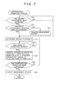
- FIG. 7 is a flowchart for compensation operation processing performed in a power storage system 10.
- the power storage system 10 keeps monitoring whether a disturbance has occurred in the power system based on a detection signal from the detector 40 (S20).
- a system disturbance will be referred to simply as a "disturbance.”
- the power storage system 10 determines whether the location of the disturbance has been determined by analyzing a detection signal from the detector 40 (S21) . When the disturbance location has not been determined (S21: NO), the power storage system gives an inquiry to the management system 60 regarding information about disturbance occurrence (S22). In cases where a disturbance to be quickly responded to occurs, an inquiry may be sent upon detection of the disturbance (S20: YES) to the management system 60 regarding information about disturbance occurrence (S22).
- the power storage system 10 determines a device (capacitor 11 or storage battery 12) to perform compensation operation (S22). For example, when the disturbance requires to be quickly responded to, the quick-responding capacitor 11 is selected.
- the power storage system 10 refers to the order of operation C117. included in the basic system information T11 and confirms the order of operation allocated thereto (S24). When the power storage system 10 determines that the order of operation allocated thereto has arrived (S24: YES), the power storage system 10 starts a predetermined compensation operation (S25).
- the power storage system 10 is the first power storage system to respond to occurrence of a disturbance in the district associated with the group.
- the power storage system 10 allocated with order-of-operation no. 1 starts compensation operation immediately without waiting for a notification from the management system 60 so as to suppress or mitigate the disturbance.
- the power storage system 10 waits for a notification from the management system 60 and starts compensation operation only after confirming that the order of operation allocated thereto has arrived. For example, a power storage system 10 allocated with order-of-operation no. 3 starts compensation operation after the power storage systems allocated with order-of-operation no. 1 and no. 2, respectively, started compensation operations.
- the power storage system 10 determines whether the compensation operation has been completed (S26). When the disturbance has been removed by the charging/discharging operation of the first-selected device only (e.g., by the capacitor 11) (S26: YES), the power storage system 10 notifies the management system 60 accordingly (S27).
- processing returns to S23 to select a next device to perform charging/discharging (e.g., the storage battery 12).
- the power storage system 60 starts compensation operation using the newly selected device (S25).
- the power storage system 10 determines that the compensation operation has been completed (S26: YES) and notifies the management system 60 of the completion of the compensation operation (S27).
- the power storage system 10 can make a next device (e.g., the storage battery 12) perform charging/discharging operation (S25, S26).
- a configuration may be used in which a waiting time unique to the power system is set as a time for confirming the effect of compensation by charging/discharging operation and in which a next device is made to perform charging/discharging after elapsing of the waiting time unique to the power system.
- a mode may be entered in which charging/discharging operation is prohibited until elapsing of a predetermined time.
- compensation operation by another power storage system 10 can be started after elapsing of a predetermined amount of time.
- the timing of starting compensation operation by the power storage systems 10 allocated with order-of-operation no. 2 or lower is adjusted by the management system 60.
- the order of operation to be allocated to and the type of compensation operation to be performed by each power storage system 10 can be determined by a prior simulation.
- the management system 60 assumes various types of disturbances and determines, for each disturbance, all patterns of compensation operation to be performed by power storage systems 10 located near the location of the disturbance.
- the management system 60 forecasts the effect of compensation operation of each of the determined patterns and sets the order of operation to be allocated to and the type of compensation operation to be performed by each power storage system 10 in the basic system information T11.
- the basic system information T11 shown in FIG. 4 shows only one order of operation for each power storage system.
- plural orders of operation may be set for each power storage system corresponding to plural disturbances.
- a power storage system 10 may be allocated with order-of-operation no. 1 for one disturbance and with order-of-operation no. 3 for another disturbance.
- the management system 60 can appropriately update the basic system information T11 by conducting simulations periodically or irregularly.
- the latest basic system information T11 updated in the management system 60 is preferably set approximately simultaneously in all power storage systems 10 managed by the management system 60. In cases where all the power storage systems 10 cannot be updated approximately simultaneously, the management system 60 may first update the basic system information T11 in such power storage systems 10 which allow updating of the basic system information T11.
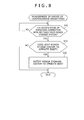
- FIG. 8 is a flowchart for management by the management system 60 of the order of compensation operations.
- the management system 60 is notified of completion of compensation operation from a power storage system 10 (S30: YES).
- the management system 60 determines, by referring to the basic system information T11, whether a power storage system 10 to operate next exists (S31) . When a power storage system 10 to operate next exists (S31: YES), the management system 60 notifies the power storage system 10 that compensation operation can be started (S32).
- the management system 60 ends the processing.
- the management system 60 may select one or more power storage systems 10 belonging to a different group and have them start compensation operation.
- the management system 10 may request cooperation of the computer system installed in the power feed instruction center managing the power system.
- the power feed instruction center severs the connection between the distribution line 4 where the disturbance is present and the power system or adjusts the output of the large-scale power station 70.
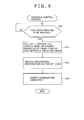
- FIG. 9 is a flowchart for schedule control processing.
- FIG. 9 will be described using the load 30 (the load 30(1) shown in FIG. 1 ) as an example load, information on the operating state, activated or stopped, of which can be obtained by the power storage system 10.
- the power storage system 10 refers to the schedule control information T12 and determines whether a time specified in the schedule control information T12 has arrived (S40).
- the power storage system 10 calculates a required compensation amount based on dynamic properties of the target load 30 and reads the corresponding preset reference data (S41). The power storage system 10 obtains operational information on the target load 30 (S42).
- the power storage system 10 starts a predetermined compensation operation upon detection of activation of the target load 30 (S43).
- the power storage system 10 may start the predetermined compensation operation before activation of the target load 30.
- the power storage system 10 may be made to start the predetermined compensation operation when the target load 30 is stopped.
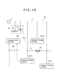
- FIG. 10 is a diagram for explaining how to deal with a disturbance occurring in a looped power system.
- Power storage systems 10(4) , 10(5), and 10(6) are connected to a looped power system.
- the power storage systems 10(5) and 10(6) are located as if sandwiching a disturbance DP. In other words, assume that the disturbance DP has occurred between the power storage system 10(5) and the power storage system 10(6).
- the power storage system 10(5) When, for the disturbance DP, the power storage system 10(5) is allocated with order-of-operation no. 1 and the power storage system 10(6) is allocated with order-of-operation no. 2, the power storage system 10(5) of order-of-operation no. 1 immediately starts compensation operation.
- the power storage system 10(6) allocated with order-of-operation no. 2 starts compensation operation after being notified by the management system 60.
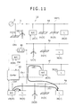
- FIG. 11 shows a power system provided with many dispersed power sources (21 (1) to 21 (5) and 22 (1) to 22(3), many loads 30 (3) to 30(7), and many power storage systems 10(7) to 10(10).
- the power storage system 10(10) located closest to the load 30 (6) and allocated with order-of-operation no. 1 immediately starts compensation operation as indicated by arrow (I).
- the power storage system 10(10) located closest to the load 30(7) and allocated with order-of-operation no. 1 immediately starts compensation operation (discharging) as indicated by arrow (II).
- the power storage system 10(9) connected to another distribution line 4f supplies power to the distribution line 4g as indicated by arrow (III).
- the phase is assumed to be set as follows.
- phase of the power storage system 10 when power is fed from a power storage system 10 to the power system (at a time of discharging), the phase of the power storage system 10 is a little advanced from the phase of the power system while maintaining a phase difference likelihood range for achieving synchronization.
- phase of the power storage system 10 When power is fed from the power system to a power storage system 10 (at a time of charging), the phase of the power storage system 10 is a little delayed from the phase of the power system while maintaining the phase difference likelihood range for achieving synchronization. Adjusting the phase in this way makes it possible to achieve a control result in the direction of power feed in discharging and in charging.
- the power system includes plural power storage systems 10 distributed over a wide planar area.
- the plural power storage systems 10 perform compensation operations at their respective locations.
- plural small-scale power storage systems 10 respectively perform compensation operations, so that the generation of useless power flows is prevented as much as possible.
- the above phase adjustment is performed with the timing of closing the circuit breaker also taken into account.
- a power supply system 10 near the location of the disturbance starts compensation operation, so that the area affected by the disturbance can be prevented from spreading.
- plural power storage systems 10 are managed in a group and, in the group, the order of operations by the power storage systems 10 is set. Therefore, in the present embodiment, the plural power storage systems 10 distributed in the power system can collaboratively stabilize the power system. Regarding the order of operations, plural power storage systems 10 may be allocated with a same order of operation. Because doing so does not cause any confusion in cause-and-effect relationship in terms of control, and it is consequently important to achieve an improved system stabilizing effect.
- charging/discharging for returning to a standby state (charging/discharging for resetting) is to be performed under quantitative control within a range where no adverse influence is generated.
- power storage systems inversely characterized in terms of an increase/decrease inclination exist in the neighborhood it is necessary, for example, to adjust timing so as to cancel out the effects on the system of operations of such power storage systems.
- the power storage system 10 allocated with order-of-operation no. 1 immediately starts compensation operation without waiting for any notification from the management system 60, whereas the other power storage systems 10 each start compensation operation after receiving a notification from the management system 60. Therefore, the plural power storage systems relevant to a disturbance are prevented from respectively starting compensation operation, and they orderly start compensation operation according to the order of operations predetermined for them. In this way, it is possible to prevent hunting or overshooting and to effectively stabilize the power system.
- operation mode is automatically switched according to the state of communication between the management system 60 and the power storage system 10.
- FIG. 12 is a flowchart for mode switching processing performed by a power storage system 10.
- the power storage system 10 is assumed to periodically communicate with the management system 60 to determine the state of communication (S50).
- the power storage system 10 Upon detection of occurrence of a communication failure (S50: YES), the power storage system 10 changes to autonomous mode (S51). In autonomous mode, the power storage system 10 immediately starts compensation operation upon detection of a disturbance by the detector 40 without waiting for any notification from the management system 60. This is because of the possibility that the power storage system 10 cannot receive any notification from the management system 60 due to a communication failure between the power storage system 10 and the management system 60.
- the power storage system 10 Upon detecting that the communication between the power storage system 10 and the management system 60 has returned to a normal state (S52: YES), the power storage system 10 changes to collaboration mode (S53). In collaboration mode, the power storage system 10 performs compensation operation in collaboration with the other power storage systems 10 in the group as described in detail in connection with the first embodiment.
- the present embodiment configured as described above generates the same effect as the first embodiment. Furthermore, in the present embodiment, when a communication failure occurs between the power storage system 10 and the management system 60, the power storage system 10 exits collaboration mode and enters autonomous mode. In this way, it does not occur that starting of compensation operation is delayed with the power storage system 10 just waiting for a notification from the management system 60.
- a configuration may be used in which the capacity of compensation in autonomous mode is smaller than the capacity of compensation in collaboration mode.
- a third embodiment will be described with reference to FIG. 13 .
- the third embodiment will be described based on a case in which plural disturbances to be compensated for in different ways are detected.
- FIG. 13 is a flowchart for compensation operation processing to be performed by a power storage system 10 according to the present embodiment. This processing entirely includes the processing performed in steps S20 through S27 shown in FIG. 7 . Furthermore, this processing includes additional steps S60 and S61.
- the power storage system 10 determines whether any other disturbance of a different inclination has occurred (S60).
- a disturbance of a different inclination is a disturbance which differs in content from the disturbance detected in step S20 and which requires a different type of compensation operation to be performed. Assume, for example, that a disturbance has resulted from an increase in the demand for power and, as compensation operation, discharging is required. In this case, a disturbance of a different inclination may be one resulting from a decrease in the demand for power and requiring charging to be performed as compensation operation.
- the power storage system 10 changes to lock mode (S61). In lock mode, no compensation operation is performed.
- the present embodiment configured as described above generates the same effect as the first embodiment. Furthermore, in the present embodiment, when differently inclined disturbances occur at a time, the power storage system 10 changes to lock mode and performs no compensation operation. In this way, neither disturbance can be suppressed, but it is at least possible to prevent either one of the disturbances from enlarging.
- a fourth embodiment will be described with reference to FIG. 14 .
- the functions of the management system 60 are provided in a specified one of plural power storage systems 10.
- the power storage system 10 having the functions of the management system 60 manages all the power storage systems 10 in the relevant district.
- the power storage system 10 is connected with a second management system 61 via the communication network CN2.
- the manager gives predetermined instructions to a predetermined one of plural power storage systems 10 via the second management system 61. This causes the predetermined power storage system 10 to perform the functions as a management system for managing the other power storage systems 10.
- the present invention can also be represented as an invention of a power storage system as follows.
- a power storage system for stabilizing a power system comprising:
- the present invention can also be represented as an invention according to which power storage systems are made to operate in order of proximity to the location of a disturbance with lower orders of operations set for power storage systems located farther from the disturbance location based on the routing of power lines.
- Power system stabilization system 10: Power storage system, 20: Dispersed power source, 30: Load, 40: Detector, 60: Management system
Landscapes
- Engineering & Computer Science (AREA)
- Power Engineering (AREA)
- Physics & Mathematics (AREA)
- Electromagnetism (AREA)
- General Physics & Mathematics (AREA)
- Radar, Positioning & Navigation (AREA)
- Automation & Control Theory (AREA)
- Supply And Distribution Of Alternating Current (AREA)
Applications Claiming Priority (1)
| Application Number | Priority Date | Filing Date | Title |
|---|---|---|---|
| PCT/JP2012/050151 WO2013103011A1 (fr) | 2012-01-06 | 2012-01-06 | Système de stabilisation de réseau électrique et procédé de stabilisation de réseau électrique |
Publications (2)
| Publication Number | Publication Date |
|---|---|
| EP2802053A1 true EP2802053A1 (fr) | 2014-11-12 |
| EP2802053A4 EP2802053A4 (fr) | 2015-11-11 |
Family
ID=48745081
Family Applications (1)
| Application Number | Title | Priority Date | Filing Date |
|---|---|---|---|
| EP12864565.2A Withdrawn EP2802053A4 (fr) | 2012-01-06 | 2012-01-06 | Système de stabilisation de réseau électrique et procédé de stabilisation de réseau électrique |
Country Status (5)
| Country | Link |
|---|---|
| US (1) | US9671807B2 (fr) |
| EP (1) | EP2802053A4 (fr) |
| JP (1) | JP5702000B2 (fr) |
| CN (1) | CN104040822B (fr) |
| WO (1) | WO2013103011A1 (fr) |
Cited By (1)
| Publication number | Priority date | Publication date | Assignee | Title |
|---|---|---|---|---|
| EP2916417A1 (fr) * | 2014-03-04 | 2015-09-09 | Samsung SDI Co., Ltd. | Système de stockage d'énergie et son procédé de contrôle |
Families Citing this family (30)
| Publication number | Priority date | Publication date | Assignee | Title |
|---|---|---|---|---|
| US11211641B2 (en) | 2012-10-18 | 2021-12-28 | Ambri Inc. | Electrochemical energy storage devices |
| US11387497B2 (en) | 2012-10-18 | 2022-07-12 | Ambri Inc. | Electrochemical energy storage devices |
| US10541451B2 (en) | 2012-10-18 | 2020-01-21 | Ambri Inc. | Electrochemical energy storage devices |
| US11721841B2 (en) | 2012-10-18 | 2023-08-08 | Ambri Inc. | Electrochemical energy storage devices |
| US12347832B2 (en) | 2013-09-18 | 2025-07-01 | Ambri, LLC | Electrochemical energy storage devices |
| DK3058605T3 (da) | 2013-10-16 | 2024-03-04 | Ambri Inc | Tætninger til anordninger af reaktivt højtemperaturmateriale |
| WO2015058165A1 (fr) | 2013-10-17 | 2015-04-23 | Ambri Inc. | Systèmes de gestion de batterie pour des dispositifs de stockage d'énergie |
| US12142735B1 (en) | 2013-11-01 | 2024-11-12 | Ambri, Inc. | Thermal management of liquid metal batteries |
| KR101878405B1 (ko) * | 2014-04-14 | 2018-07-16 | 엘에스산전 주식회사 | 점검 기능을 가지는 에너지 저장 장치 |
| KR102243021B1 (ko) * | 2014-05-26 | 2021-04-21 | 에스케이이노베이션 주식회사 | 하이브리드 에너지 저장 시스템 및 그 제어 방법 |
| JP6296910B2 (ja) * | 2014-06-10 | 2018-03-20 | 大阪瓦斯株式会社 | 電力需給システム |
| JP6450142B2 (ja) * | 2014-10-17 | 2019-01-09 | 株式会社日立製作所 | 電力系統制御システム、電力系統制御方法、および電力変換装置 |
| JP6402002B2 (ja) * | 2014-10-30 | 2018-10-10 | 株式会社日立製作所 | 電力貯蔵システムの評価装置、評価方法および評価プログラム |
| JP6420457B2 (ja) * | 2015-02-25 | 2018-11-07 | 京セラ株式会社 | 電力変換装置、分電盤及び運転切替方法 |
| US10181800B1 (en) * | 2015-03-02 | 2019-01-15 | Ambri Inc. | Power conversion systems for energy storage devices |
| WO2016141354A2 (fr) | 2015-03-05 | 2016-09-09 | Ambri Inc. | Céramiques et joints pour dispositifs de matériau réactif à haute température |
| JP6793321B2 (ja) * | 2015-08-07 | 2020-12-02 | パナソニックIpマネジメント株式会社 | 蓄電制御システム、蓄電システム、蓄電制御装置、充放電制御装置、及び蓄電装置 |
| JP6289423B2 (ja) * | 2015-08-26 | 2018-03-07 | 東京電力ホールディングス株式会社 | 蓄電池システム制御方法 |
| DE102015119186A1 (de) * | 2015-11-06 | 2017-05-11 | EnBW Energie Baden-Württemberg AG | Kraftwerk, Kraftwerkverbund mit einem Kraftwerk sowie Betriebsverfahren |
| JP6468216B2 (ja) * | 2016-02-25 | 2019-02-13 | オムロン株式会社 | 蓄電制御装置、蓄電制御方法、および蓄電制御プログラム |
| JP6650606B2 (ja) * | 2016-07-07 | 2020-02-19 | パナソニックIpマネジメント株式会社 | 逆潮流制御システム、蓄電装置および逆潮流制御方法 |
| US11929466B2 (en) | 2016-09-07 | 2024-03-12 | Ambri Inc. | Electrochemical energy storage devices |
| DE102017202209A1 (de) | 2017-02-13 | 2018-08-16 | Siemens Aktiengesellschaft | Verfahren und Vorrichtung zur Stabilisierung einer Frequenz in einem Wechselspannungsnetz |
| CN110731027B (zh) | 2017-04-07 | 2024-06-18 | 安保瑞公司 | 具有固体金属阴极的熔盐电池 |
| WO2019203719A1 (fr) | 2018-04-20 | 2019-10-24 | Gycom Connected Residence Ab | Procédé et système d'équilibrage de puissance |
| WO2020131617A1 (fr) | 2018-12-17 | 2020-06-25 | Ambri Inc. | Systèmes et procédés de stockage d'énergie à haute température |
| JP7492859B2 (ja) * | 2020-05-19 | 2024-05-30 | 株式会社日立製作所 | 電力系統制御装置および発電システム |
| US12500436B2 (en) * | 2021-10-20 | 2025-12-16 | China Energy Investment Corporation Limited | Controller, system, and method for managing discharge or charge of heterogeneous battery packs |
| JP7843197B2 (ja) * | 2022-08-01 | 2026-04-09 | 株式会社東芝 | 系統管理装置、系統管理方法及びプログラム |
| JP2025043172A (ja) * | 2023-09-15 | 2025-03-28 | 株式会社東芝 | 制御装置、エネルギーマネジメントシステム及びコンピュータプログラム |
Family Cites Families (32)
| Publication number | Priority date | Publication date | Assignee | Title |
|---|---|---|---|---|
| JP2000006693A (ja) * | 1998-06-19 | 2000-01-11 | Nissin Electric Co Ltd | き電電圧の調整方法及び調整装置 |
| JP2003006693A (ja) * | 2001-06-21 | 2003-01-10 | Nabco Ltd | 自動ドアの保守管理方法及び自動ドアシステム |
| US6685334B2 (en) * | 2002-04-30 | 2004-02-03 | G-5 Electronics | System and method of power management for a solar powered device |
| JP2004129412A (ja) | 2002-10-03 | 2004-04-22 | Nissin Electric Co Ltd | 電力貯蔵装置 |
| JP3681735B2 (ja) * | 2003-05-21 | 2005-08-10 | 本田技研工業株式会社 | 蓄電装置の充放電制御装置、及び充放電制御方法 |
| JP4445361B2 (ja) * | 2004-09-24 | 2010-04-07 | 関西電力株式会社 | 二次電池を用いた電力系統制御方法及び電力系統制御装置 |
| US7633284B2 (en) * | 2005-03-08 | 2009-12-15 | Tennessee Valley Authority | Method and apparatus for managing ultracapacitor energy storage systems for a power transmission system |
| JP2007135355A (ja) | 2005-11-11 | 2007-05-31 | Mitsubishi Electric Corp | 系統安定化装置 |
| EP2097289A2 (fr) * | 2006-12-11 | 2009-09-09 | V2green, Inc. | Programmation et commande dans un systeme d'agregation de puissance pour ressources electriques reparties |
| JP4306775B2 (ja) * | 2007-08-31 | 2009-08-05 | トヨタ自動車株式会社 | 電動車両 |
| JP5113789B2 (ja) * | 2009-03-26 | 2013-01-09 | 株式会社日立産機システム | 充放電制御装置および充放電制御方法 |
| JP2010233353A (ja) * | 2009-03-27 | 2010-10-14 | Tokyo Electric Power Co Inc:The | 電力供給システムおよび電力供給方法 |
| US20100308765A1 (en) * | 2009-04-01 | 2010-12-09 | Eaglepicher Technologies, Llc | Hybrid energy storage system, renewable energy system including the storage system, and method of using same |
| US8655495B2 (en) * | 2009-06-24 | 2014-02-18 | Vestas Wind Systems A/S | Current control of a wind park |
| JP5479182B2 (ja) * | 2009-09-30 | 2014-04-23 | 三洋電機株式会社 | 発電システムおよび充放電制御装置 |
| US8314587B2 (en) | 2009-10-09 | 2012-11-20 | Alcatel Lucent | Method and apparatus of stored energy management in battery powered vehicles |
| EP2507674A1 (fr) * | 2009-12-03 | 2012-10-10 | A123 Systems, Inc. | Dispositif et procédé de synchronisation de charge de réseau électrique |
| KR101097259B1 (ko) * | 2009-12-11 | 2011-12-21 | 삼성에스디아이 주식회사 | 전력 저장을 위한 장치 및 제어 방법 |
| EP2518856B1 (fr) * | 2009-12-24 | 2018-01-24 | Hitachi, Ltd. | Système de contrôle d'alimentation en électricité utilisant des véhicules électriques, appareil de contrôle d'alimentation en électricité, appareil de distribution d'informations et procédé de distribution d'informations |
| US8588989B1 (en) * | 2010-04-29 | 2013-11-19 | Google Inc. | Power-consuming facilities as a source of reserve power |
| KR101158214B1 (ko) * | 2010-09-27 | 2012-06-19 | 삼성전기주식회사 | 에너지 저장체의 전압 안정화 장치 및 그 방법 |
| KR101273811B1 (ko) * | 2010-10-25 | 2013-06-11 | 삼성전기주식회사 | 에너지 저장체의 전압 안정화 장치 및 그 방법 |
| EP2485356A1 (fr) * | 2011-02-02 | 2012-08-08 | Arista Power, Inc. | Stockage de l'énergie et système de gestion de l'alimentation |
| KR20120133459A (ko) * | 2011-05-31 | 2012-12-11 | 삼성전기주식회사 | 에너지 저장체의 전압 안정화 장치 |
| WO2013030952A1 (fr) * | 2011-08-30 | 2013-03-07 | 株式会社日立製作所 | Système de stabilisation de système électrique |
| DE102011055225A1 (de) * | 2011-11-10 | 2013-05-16 | Evonik Degussa Gmbh | Verfahren zur Bereitstellung von Regelleistung |
| DE102011055228A1 (de) * | 2011-11-10 | 2013-05-16 | Evonik Degussa Gmbh | Verfahren zur Bereitstellung von Regelleistung mit einem Energiespeicher unter Ausnutzung von Toleranzen beim Zeitpunkt der Regelleistungserbringung |
| US10756543B2 (en) * | 2012-09-13 | 2020-08-25 | Stem, Inc. | Method and apparatus for stabalizing power on an electrical grid using networked distributed energy storage systems |
| US9634508B2 (en) * | 2012-09-13 | 2017-04-25 | Stem, Inc. | Method for balancing frequency instability on an electric grid using networked distributed energy storage systems |
| WO2014132321A1 (fr) * | 2013-02-26 | 2014-09-04 | 株式会社 日立製作所 | Dispositif source d'énergie |
| EP2992581B1 (fr) * | 2013-04-29 | 2017-07-12 | Caterva GmbH | Système électrique permettant de fournir un service de réseau à un réseau électrique |
| EP2827467A3 (fr) * | 2013-07-18 | 2015-04-22 | Solantro Semiconductor Corp. | Génération de puissance stabilisée |
-
2012
- 2012-01-06 JP JP2013552373A patent/JP5702000B2/ja active Active
- 2012-01-06 EP EP12864565.2A patent/EP2802053A4/fr not_active Withdrawn
- 2012-01-06 CN CN201280066364.9A patent/CN104040822B/zh not_active Expired - Fee Related
- 2012-01-06 WO PCT/JP2012/050151 patent/WO2013103011A1/fr not_active Ceased
- 2012-01-06 US US14/370,071 patent/US9671807B2/en not_active Expired - Fee Related
Cited By (2)
| Publication number | Priority date | Publication date | Assignee | Title |
|---|---|---|---|---|
| EP2916417A1 (fr) * | 2014-03-04 | 2015-09-09 | Samsung SDI Co., Ltd. | Système de stockage d'énergie et son procédé de contrôle |
| US10763682B2 (en) | 2014-03-04 | 2020-09-01 | Samsung Sdi Co., Ltd. | Energy storage system and controlling method thereof |
Also Published As
| Publication number | Publication date |
|---|---|
| US20140365027A1 (en) | 2014-12-11 |
| CN104040822A (zh) | 2014-09-10 |
| EP2802053A4 (fr) | 2015-11-11 |
| CN104040822B (zh) | 2016-12-07 |
| JPWO2013103011A1 (ja) | 2015-05-11 |
| WO2013103011A1 (fr) | 2013-07-11 |
| JP5702000B2 (ja) | 2015-04-15 |
| US9671807B2 (en) | 2017-06-06 |
Similar Documents
| Publication | Publication Date | Title |
|---|---|---|
| US9671807B2 (en) | Power grid stabilization system and power grid stabilization method | |
| US12224583B2 (en) | Highly flexible, electrical distribution grid edge energy manager and router | |
| US11043811B2 (en) | Reactive power control method, device and system | |
| US20210013717A1 (en) | Highly Flexible Electrical Distribution Grid Edge Energy Manager and Router | |
| US11070057B2 (en) | Method for starting an energy generation network | |
| WO2018024234A1 (fr) | Procédé de commande de puissance, dispositif, appareil onduleur et contrôleur de centrale électrique | |
| US10033220B1 (en) | High-voltage energy storage system | |
| CN102948030A (zh) | 可再生能量发电管理 | |
| Dolan et al. | Modelling and delivery of an active network management scheme for the Northern Isles new energy solutions project | |
| CN104917278A (zh) | 冗余不间断电源系统 | |
| Adnan et al. | Cascading failures assessment in renewable integrated power grids under multiple faults contingencies | |
| US20210294406A1 (en) | Datacenter power management using current injection | |
| US20210344217A1 (en) | Datacenter current injection for power management | |
| CN116683644A (zh) | 管理数据中心中的电力 | |
| JP5797122B2 (ja) | 分散型電力管理システム | |
| US12519313B2 (en) | Dispatchable datacentre energy system and a method of operation | |
| Cengizer et al. | Optimization based approach to solve phase balancing problem in the distribution system | |
| Wang et al. | Development of a microgrid control system for a solar-plus-battery microgrid to support a critical facility | |
| WO2023027137A1 (fr) | Dispositif de commande d'énergie, système de commande d'énergie et procédé de commande d'énergie | |
| CN120341946B (zh) | 一种微电网中储能装置的监测控制方法 | |
| CN120377465B (zh) | 一种配电方舱控制方法、系统、智能终端及存储介质 | |
| US12537383B1 (en) | Microgrid configuration optimization for battery agnostic systems | |
| EP3542434B1 (fr) | Infrastructure de commande décentralisée sans communication de production d'energie distribuée dans des micro-réseaux | |
| WO2021145018A1 (fr) | Dispositif serveur, dispositif de conversion de puissance, système de réseau électrique, et procédé de gestion de dispositif de conversion de puissance | |
| Arcanjo et al. | Hybrid PV-Battery Storage System for Substation Resilience: Field Deployment and Operational Assessment |
Legal Events
| Date | Code | Title | Description |
|---|---|---|---|
| PUAI | Public reference made under article 153(3) epc to a published international application that has entered the european phase |
Free format text: ORIGINAL CODE: 0009012 |
|
| 17P | Request for examination filed |
Effective date: 20140806 |
|
| AK | Designated contracting states |
Kind code of ref document: A1 Designated state(s): AL AT BE BG CH CY CZ DE DK EE ES FI FR GB GR HR HU IE IS IT LI LT LU LV MC MK MT NL NO PL PT RO RS SE SI SK SM TR |
|
| DAX | Request for extension of the european patent (deleted) | ||
| RA4 | Supplementary search report drawn up and despatched (corrected) |
Effective date: 20151008 |
|
| RIC1 | Information provided on ipc code assigned before grant |
Ipc: H02J 3/46 20060101ALI20151002BHEP Ipc: H02J 3/32 20060101AFI20151002BHEP |
|
| STAA | Information on the status of an ep patent application or granted ep patent |
Free format text: STATUS: EXAMINATION IS IN PROGRESS |
|
| 17Q | First examination report despatched |
Effective date: 20200312 |
|
| STAA | Information on the status of an ep patent application or granted ep patent |
Free format text: STATUS: THE APPLICATION IS DEEMED TO BE WITHDRAWN |
|
| 18D | Application deemed to be withdrawn |
Effective date: 20200723 |