EP2916417A1 - Système de stockage d'énergie et son procédé de contrôle - Google Patents
Système de stockage d'énergie et son procédé de contrôle Download PDFInfo
- Publication number
- EP2916417A1 EP2916417A1 EP15157048.8A EP15157048A EP2916417A1 EP 2916417 A1 EP2916417 A1 EP 2916417A1 EP 15157048 A EP15157048 A EP 15157048A EP 2916417 A1 EP2916417 A1 EP 2916417A1
- Authority
- EP
- European Patent Office
- Prior art keywords
- charge
- battery rack
- power
- battery
- state
- Prior art date
- Legal status (The legal status is an assumption and is not a legal conclusion. Google has not performed a legal analysis and makes no representation as to the accuracy of the status listed.)
- Granted
Links
Images


Classifications
-
- H—ELECTRICITY
- H02—GENERATION; CONVERSION OR DISTRIBUTION OF ELECTRIC POWER
- H02J—ELECTRIC POWER NETWORKS; CIRCUIT ARRANGEMENTS OR SYSTEMS FOR SUPPLYING OR DISTRIBUTING ELECTRIC POWER; SYSTEMS FOR STORING ELECTRIC ENERGY
- H02J3/00—Circuit arrangements for AC mains or AC distribution networks
- H02J3/28—Arrangements for balancing of the load in networks by storage of energy
- H02J3/32—Arrangements for balancing of the load in networks by storage of energy using batteries or super capacitors with converting means
-
- H—ELECTRICITY
- H02—GENERATION; CONVERSION OR DISTRIBUTION OF ELECTRIC POWER
- H02J—ELECTRIC POWER NETWORKS; CIRCUIT ARRANGEMENTS OR SYSTEMS FOR SUPPLYING OR DISTRIBUTING ELECTRIC POWER; SYSTEMS FOR STORING ELECTRIC ENERGY
- H02J7/00—Circuit arrangements for charging or discharging batteries or for supplying loads from batteries
- H02J7/50—Circuit arrangements for charging or discharging batteries or for supplying loads from batteries acting upon multiple batteries simultaneously or sequentially
-
- H—ELECTRICITY
- H02—GENERATION; CONVERSION OR DISTRIBUTION OF ELECTRIC POWER
- H02J—ELECTRIC POWER NETWORKS; CIRCUIT ARRANGEMENTS OR SYSTEMS FOR SUPPLYING OR DISTRIBUTING ELECTRIC POWER; SYSTEMS FOR STORING ELECTRIC ENERGY
- H02J7/00—Circuit arrangements for charging or discharging batteries or for supplying loads from batteries
- H02J7/50—Circuit arrangements for charging or discharging batteries or for supplying loads from batteries acting upon multiple batteries simultaneously or sequentially
- H02J7/52—Circuit arrangements for charging or discharging batteries or for supplying loads from batteries acting upon multiple batteries simultaneously or sequentially for charge balancing, e.g. equalisation of charge between batteries
-
- H—ELECTRICITY
- H02—GENERATION; CONVERSION OR DISTRIBUTION OF ELECTRIC POWER
- H02J—ELECTRIC POWER NETWORKS; CIRCUIT ARRANGEMENTS OR SYSTEMS FOR SUPPLYING OR DISTRIBUTING ELECTRIC POWER; SYSTEMS FOR STORING ELECTRIC ENERGY
- H02J7/00—Circuit arrangements for charging or discharging batteries or for supplying loads from batteries
- H02J7/60—Circuit arrangements for charging or discharging batteries or for supplying loads from batteries including safety or protection arrangements
-
- H—ELECTRICITY
- H02—GENERATION; CONVERSION OR DISTRIBUTION OF ELECTRIC POWER
- H02J—ELECTRIC POWER NETWORKS; CIRCUIT ARRANGEMENTS OR SYSTEMS FOR SUPPLYING OR DISTRIBUTING ELECTRIC POWER; SYSTEMS FOR STORING ELECTRIC ENERGY
- H02J7/00—Circuit arrangements for charging or discharging batteries or for supplying loads from batteries
- H02J7/70—Circuit arrangements for charging or discharging batteries or for supplying loads from batteries characterised by the mechanical construction
-
- H—ELECTRICITY
- H02—GENERATION; CONVERSION OR DISTRIBUTION OF ELECTRIC POWER
- H02J—ELECTRIC POWER NETWORKS; CIRCUIT ARRANGEMENTS OR SYSTEMS FOR SUPPLYING OR DISTRIBUTING ELECTRIC POWER; SYSTEMS FOR STORING ELECTRIC ENERGY
- H02J9/00—Circuit arrangements for emergency or stand-by power supply, e.g. for emergency lighting
- H02J9/04—Circuit arrangements for emergency or stand-by power supply, e.g. for emergency lighting in which the distribution system is disconnected from the normal source and connected to a standby source
- H02J9/06—Circuit arrangements for emergency or stand-by power supply, e.g. for emergency lighting in which the distribution system is disconnected from the normal source and connected to a standby source with automatic change-over, e.g. UPS systems
- H02J9/062—Circuit arrangements for emergency or stand-by power supply, e.g. for emergency lighting in which the distribution system is disconnected from the normal source and connected to a standby source with automatic change-over, e.g. UPS systems for AC powered loads
Definitions
- the present invention relates to an energy storage system and a controlling method thereof, and, more particularly, to an energy storage system and a controlling method thereof, enabling the frequency of power flowing in an electric-power system to be continuously regulated, in other words to provide frequency regulation in an electric power system.
- An energy storage system is a system that uses the new renewable energy, a battery system and an existing electric-power system in conjunction with each other.
- Such an energy storage system is configured to include a battery system that stores power, and a power conversion system that properly converts power of the battery system, a power generation system, and an electric-power system and then supplies the converted power.
- the energy storage system may perform an uninterruptible power supply (UPS) operation. Further, if the frequency is changed depending on a change in consumption of power flowing in the electric-power system, the energy storage system may perform frequency regulation to maintain a desired frequency by charging or discharging power stored in the battery system, thus allowing a frequency to be kept constant.
- UPS uninterruptible power supply
- the energy storage system When the energy storage system is operated to regulate the frequency, it is required to continuously and randomly charge or discharge the battery system. However, when the battery system comes into a full charge state or a full discharge state due to the accumulation of the charging or discharging operations, the charging or discharging operation may be stopped. In this case, the state of charge (SOC) of the battery system should be regulated to 50% again and then resume the charging or discharging operation to perform the frequency regulation again, thus causing inconvenience.
- SOC state of charge
- an object of the present invention is to provide an energy storage system and a controlling method thereof, enabling the frequency of power flowing in an electric-power system to be continuously regulated.
- an energy storage system including a power conversion system configured to produce a control signal for regulating a frequency of power flowing from a power generation system to an electric-power system; and a battery system including a first battery rack and a second battery rack, wherein the battery system further includes a charge/discharge unit configured to perform a charging/discharging operation of the second battery rack; and a rack battery management system (BMS) configured to control the charging/discharging operation of the first and second battery racks using the control signal, and to control the charge/discharge unit, thus controlling a state of charge (SOC) of the second battery rack.
- BMS rack battery management system
- the control signal may include a charge control signal causing the power to be charged into the first or second battery rack when the frequency of the power flowing in the electric-power system exceeds a predetermined value, and a discharge control signal causing the first or second battery rack to be discharged, thus supplying power to the electric-power system when the frequency of the power flowing in the electric-power system falls to be less than the predetermined value.
- the rack BMS may perform control such that the power is charged into the first battery rack when a state of charge of the first battery rack is less than a first preset state of charge, and may perform control such that the power is charged into the second battery rack when the state of charge of the first battery rack is equal to or more than the first preset state of charge.
- the rack BMS may control the charge/discharge unit such that the state of charge of the second battery rack maintains the second preset state of charge, thus discharging the second battery rack.
- the rack BMS may perform control such that the first battery rack is discharged when a state of charge of the first battery rack is more than a third preset state of charge, and may perform control such that the second battery rack is discharged when the state of charge of the first battery rack is equal to or less than the third preset state of charge.
- the rack BMS may control the charge/discharge unit such that the state of charge of the second battery rack maintains the fourth preset state of charge, thus charging the second battery rack.
- the rack BMS may control the charge/discharge unit such that the state of charge of the second battery rack has a fifth preset state of charge.
- the fifth preset state of charge may be about 50%.
- a discharge rate of the second battery rack may be larger than a discharge rate of the first battery rack.
- a method of controlling an energy storage system including a battery system having a first battery rack, a second battery rack, and a charge/discharge unit configured to charge or discharge the second battery rack; and a power conversion system configured to transmit a control signal, regulating a frequency of power flowing from a power generation system to an electric-power system, to the battery system, the method including determining a priority of charging/discharging the first battery rack or the second battery rack using the control signal and a state of charge of the first battery rack; charging/discharging the first battery rack or the second battery rack to regulate the frequency depending on the determined priority; and controlling a state of charge of the second battery rack to a preset state of charge using the charge/discharge unit.
- the present invention it is possible to continuously carry out a charging/discharging operation of a battery system that is performed so as to regulate a frequency in an energy storage system.
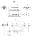
- the energy storage system 1 is configured to supply power to a load 4, in conjunction with a power generation system 2 and an electric-power system 3.
- the power generation system 2 is a system that produces power using an energy source.
- the power generation system 2 is configured to supply produced power to the energy storage system 1.
- the power generation system 2 may be a solar-light power generation system, a wind power generation system, a tidal power generation system, etc. However, they are to be regarded as illustrative but the power generation system 2 is not limited to the above-mentioned things.
- the power generation system 2 may include all kinds of power generation systems that produce power using new renewable energy such as solar heat or geothermal heat. Particularly, since it is easy to install a solar cell configured to produce electrical energy using solar-light in a home, a factory, etc., the solar cell is suitable for the energy storage system 1 in the home or factory.
- the power generation system 2 may be provided with a plurality of power generation modules arranged in parallel and produce power every power generation module, thus constituting a high-capacity energy system.
- the electric-power system 3 includes a power plant, a substation, a power line, etc.
- the electric-power system 3 When the electric-power system 3 is in a normal state, it supplies power to the energy storage system 1 to render the power to be supplied to the load 4 and/or the battery system 20, and the electric-power system 3 is supplied with power from the energy storage system 1.
- the electric-power system 3 when the electric-power system 3 is in an abnormal state, the supply of power from the electric-power system 3 to the energy storage system 1 is stopped, and the supply of power from the energy storage system 1 to the electric-power system 3 is likewise stopped.
- the load 4 consumes power produced from the power generation system 2, power stored in the battery system 20, or power supplied from the electric-power system 3.
- a home, factory, or the like may be an example of the load 4.
- the energy storage system 1 includes the battery system 20 configured to store power, and a power conversion system 10 configured to properly convert the power from the battery system 20, the power generation system 2, the electric-power system 3 and then supply the converted power.
- the energy storage system 1 may store power, produced from the power generation system 2, in the battery system 20, and may supply the produced power to the electric-power system 3.
- the energy storage system 1 may supply power stored in the battery system 20 to the electric-power system 3, or may store power, supplied from the electric-power system 3, in the battery system 20.
- the electric-power system 3 When the electric-power system 3 is in an abnormal state, for example, a power failure occurs, the energy storage system 1 performs a UPS operation to supply power to the load 4. Meanwhile, even when the electric-power system 3 is in a normal state, the energy storage system 1 may supply power produced from the power generation system 2 or power stored in the battery system 20 to the load 4.
- the energy storage system may perform frequency regulation to maintain a desired frequency by charging or discharging power stored in the battery system 20, thus allowing a frequency to be kept constant. That is, for the purpose of regulating the frequency, when the frequency of power flowing in the electric-power system is high, the energy storage system 1 may supply power, produced from the power generation system 2, to the battery system 20. On the other hand, when the frequency is low, the energy storage system 1 may discharge the power stored in the battery system 20 and then supply it to the electric-power system 3.
- FIG. 2 is a block diagram showing the configuration of the energy storage system 1 according to an embodiment of the present invention.
- the energy storage system 1 includes the power conversion system 10 configured to control power conversion, the battery system 20, a first switch 30, a second switch 40, and others.
- the power conversion system 10 converts power supplied from the power generation system 2, the electric-power system 3, and the battery system 20 into a form suitable for the electric-power system 3, the load 4, and the battery system 20.
- the power conversion system 10 performs the conversion of power to an input/output terminal or the conversion of power from the input/output terminal.
- the power conversion may be DC/AC conversion and conversion between first and second voltages.
- the power conversion system 10 supplies converted power to a desired place depending on an operation mode under the control of an integrated controller 15.
- the power conversion system 10 includes a power conversion unit 11, a DC link unit 12, an inverter 13, a converter 14, and the integrated controller 15.
- the power conversion unit 11 is a power conversion device that is connected between the power generation system 2 and the DC link unit 12.
- the power conversion unit 11 is configured to transmit power, produced from the power generation system 2, to the DC link unit 12.
- An output voltage from the power conversion unit 11 is a DC link voltage.
- the power conversion unit 11 may comprise a power conversion circuit, such as a converter or a rectifier circuit, depending on the kind of the power generation system 2. For example, if the power generation system 2 produces DC power, the power conversion unit 11 may include a converter for converting the voltage level of the DC power of the power generation system 2 into the voltage level of the DC power of the DC link unit 12. However, if the power generation system 2 produces AC power, the power conversion unit 11 may be a rectifier circuit for converting alternating current into direct current.
- a power conversion circuit such as a converter or a rectifier circuit
- the power conversion unit 11 may include an MPPT converter that performs a maximum power point tracking control to maximally obtain power produced from the power generation system 2 depending on several conditions such as a quantity of solar radiation or a temperature.
- the power conversion unit 11 may stop operating so as to minimize power consumption when no power is produced from the power generation system 2.
- the DC link voltage may become unstable due to an instantaneous voltage drop of the power generation system 2 or the electric-power system 3, a sudden change in the load 4 or the requirement of high load.
- the DC link voltage should be stabilized to normally operate the converter 14 and the inverter 13.
- the DC link unit 12 is connected between the power conversion unit 11 and the inverter 13 to keep the DC link voltage constant.
- a high-capacity capacitor may be included as the DC link unit 12.
- the inverter 13 is a power conversion device that is connected between the DC link unit 12 and the first switch 30.
- the inverter 13 may comprise an inverter that converts DC output voltage from the DC link unit 12 into AC voltage of the electric-power system 3 in a discharge mode. Further, the inverter 13 may include a rectifier circuit that rectifies the AC voltage of the electric-power system 3, converts the AC voltage into the DC link voltage, and outputs the converted voltage so as to store the power of the electric-power system 3 in the battery system 20 in a charge mode. That is, the inverter 13 may be a bi-directional inverter that is changeable in input and output directions.
- the inverter 13 may include a filter for removing harmonic waves from AC voltage that is output to the electric-power system 3. Further, the inverter 13 may include a phase locked loop (PLL) circuit for synchronizing an AC voltage phase that is output from the inverter 13 with an AC voltage phase of the electric-power system 3 so as to suppress reactive power loss. Moreover, the inverter 13 may perform several functions, for example, restriction on a voltage fluctuation range, improvement on a power factor, removal of a DC component, and protection against transient phenomena. When the inverter 13 is not in use, it may stop operating so as to minimize power consumption.
- PLL phase locked loop
- the converter 14 is a power conversion device that is connected between the DC link unit 12 and the battery system 20.
- the converter 14 includes a DC-DC converter that converts the voltage of power output from the battery system 20 into the DC link voltage for the inverter 13 in the discharge mode.
- the converter 14 may include a DC-DC converter that converts the voltage of power output from the power conversion unit 11 or the inverter 13 into the voltage for the battery system 20 in the charge mode. That is, the converter 14 may be a bi-directional converter that is changeable in input and output directions. When the converter 14 is not used to charge or discharge the battery system 20, the converter 14 stops operating, thus minimizing power consumption.
- the integrated controller 15 monitors the state of the power generation system 2, the electric-power system 3, the battery system 20 and the load 4, and controls the operation of the power conversion unit 11, the inverter 13, the converter 14, the battery system 20, the first switch 30, and the second switch 40 depending on the monitored result.
- the integrated controller 15 may monitor whether a power failure occurs in the electric-power system 3 or not and whether power produces from the power generation system 2 or not, and may monitor a production amount of the power if it is produced from the power generation system 2, the charging state of the battery system 20, the power consumption of the load 4, a time, etc.
- the integrated controller 15 may control the load 4 to determine the priority of power utilization devices included in the load 4, and supply power to a power utilization device having a high priority.
- the integrated controller 15 may perform frequency regulation for maintaining a desired frequency by charging or discharging power stored in the battery system 20, thus maintaining a constant frequency. That is, if the frequency of the power flowing in the electric-power system 3 for regulating the frequency is high, power produced from the power generation system 2 is supplied to the battery system 20. Meanwhile, if the frequency is low, power stored in the battery system 20 may be discharged and supplied to the electric-power system 3.
- the integrated controller 15 may transmit a control signal for regulating the frequency to the battery system 20.
- the control signal may include a charge control signal causing the power to be charged into the battery system 20 when the frequency of the power flowing in the electric-power system 3 exceeds a predetermined value, and a discharge control signal causing the power stored in the battery system 20 to be discharged, thus supplying the power to the electric-power system 3 when the frequency of the power flowing in the electric-power system 3 falls to be less than the predetermined value.
- the battery system operated in response to the control signal for regulating the frequency will be described below in detail with reference to FIGS. 3 and 4 .
- the first switch 30 and the second switch 40 are connected between the inverter 13 and the electric-power system 3 in series, and perform an ON/OFF operation under the control of the integrated controller 15, thus controlling a current flow between the power generation system 2 and the electric-power system 3.
- the ON/OFF state of the first switch 30 and the second switch 40 may be determined depending on the state of the power generation system 2, the electric-power system 3 and the battery system 20.
- the first switch 30 is turned on.
- the second switch 40 is turned on.
- the first and second switches 30 and 40 it is possible to use a switching device such as a relay that may withstand a large magnitude of current.
- the second switch 40 When a power failure occurs in the electric-power system 3, the second switch 40 is turned off and the first switch 30 is turned on. That is, while power is supplied from the power generation system 2 and/or the battery system 20 to the load 4, the power supplied to the load 4 is prevented from flowing towards the electric-power system 3.
- the energy storage system 1 is disconnected from the electric-power system 3 where a power failure occurs, thus preventing power from being supplied to the electric-power system 3. Hence, this prevents a worker who works on a power line or the like of the electric-power system 3, for example, repairs the power failure of the electric-power system 3 from getting a shock from the energy storage system 1.
- the battery system 20 is supplied with power from the power generation system 2 and/or the electric-power system 3 to store the power, and supplies the power stored in the load 4 or the electric-power system 3.
- the battery system 20 may include a power storing portion and a portion for controlling and protecting the power storing portion.
- the battery system 20 will be described in detail with reference to FIG. 3 .
- FIG. 3 is a view showing the configuration of a battery system according to an embodiment of the present invention.
- the battery system 20 may include a battery rack 110, a rack battery management system (BMS) 120, a rack protection circuit 130, and a charge/discharge unit 140.
- BMS rack battery management system
- the battery rack 110 stores power supplied from an outside, namely, the power generation system 2 and/or the electric-power system 3, and supplies the stored power to the power generation system 2 and/or the electric-power system 3.
- the battery rack 110 may include one or more battery trays that are connected in series and/or in parallel to serve as a plurality of subunits. Further, each battery tray may include a plurality of battery cells as the subunits.
- Various secondary batteries that are rechargeable may be used for the battery cells.
- the secondary battery used for the battery cell may include one or more batteries selected from a group including a nickel-cadmium battery, a lead storage battery, a nickel metal hydride battery (NiMH), a lithium ion battery, a lithium polymer battery, etc.
- the battery rack 110 may include a first battery rack 111 and a second battery rack 113.
- the first battery rack 111 may include battery cells suitable for low-speed operation
- the second battery rack 113 may include battery cells suitable for high-speed operation.
- the discharge rate of the battery cells included in the second battery rack 113 may be larger than the discharge rate of the battery cells included in the first battery rack 111. That is, the second battery rack 113 may perform a charging/discharging operation at higher speeds in comparison to the first battery rack 111, and the state of charge of the second battery rack 113 may be rapidly controlled by a separate charge/discharge unit 140 that will be described below.
- the rack BMS 120 is connected to the battery rack 110, and controls the charging/discharging operation of the battery rack 110 using a control signal Sf transmitted from the integrated controller 15 of the power conversion system 10 to regulate a frequency. Further, the rack BMS 120 may perform an overcharge protection function, an over-discharge protection function, an overcurrent protection function, an overvoltage protection function, an overheat protection function, a cell balancing function, etc. To this end, the rack BMS 120 may receive monitoring data Dm on a voltage, a current, a temperature, a remaining power, a life span, a charging state, a state of charge (SOC), and others from the battery rack 110, and may produce a control signal Sc in response to the monitored result to control the battery rack 110.
- SOC state of charge
- the rack BMS 120 performs control using the charge/discharge unit 140 such that the state of charge of the second battery rack has a constant value. Further, the rack BMS 120 may apply the received monitoring data Dm to the integrated controller 15 of the power conversion system 10, and may receive instructions on the control of the battery rack 110 from the integrated controller 15.
- the rack protection circuit 130 is connected between input/output terminals (I/O T+, I/O T-) that are connected to the battery rack 110 and the converter 14 of the power conversion system 10, thus preventing the battery rack 110 from being damaged.
- the rack protection circuit 130 may receive a control signal Sp from the rack BMS 120 to control the flow of a current in response to the control signal Sp. Further, the rack protection circuit 130 may measure the output voltage or output current of the battery rack 110 and then transmit a measured signal Sd to the rack BMS 120.
- the rack protection circuit 130 may be physically separated from the rack BMS 120.
- the rack BMS 120 is configured to be separated from the rack protection circuit 130 located on a high current path, thus allowing the rack BMS 120 to be protected from high current.
- the charge/discharge unit 140 performs the charging/discharging operation of the second battery rack 113.
- the charge/discharge unit 140 may forcibly charge the second battery rack 113 using external power or may forcibly discharge the second battery rack 113 by connecting it to an external load, under the control of the rack BMS 120.
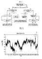
- FIG. 4 is a flowchart showing a method of controlling the energy storage system for regulating the frequency according to an embodiment of the present invention.
- the frequency regulating method of the battery system according to the embodiment of the present invention will be described below with reference to FIGS. 3 and 4 .
- the rack BMS 120 receives a control signal for controlling the frequency of power flowing in the electric-power system 3, from the power conversion system 10, at step S101.
- control signal may include a charge control signal causing the power to be charged into the battery system 20 when the frequency of the power flowing in the electric-power system 3 exceeds a predetermined value, and a discharge control signal causing the power stored in the battery system 20 to be discharged, thus supplying the power to the electric-power system 3 when the frequency of the power flowing in the electric-power system 3 falls to be less than the predetermined value.
- the rack BMS 120 determines whether the control signal is the charge control signal or the discharge control signal, at step S103.
- the rack BMS 120 compares the state of charge of the first battery rack 111 with a first preset state of charge so as to determine the priority of charging the first battery rack 111 and the second battery rack 113, at step S105.
- the first preset state of charge is a value determining that the battery rack will come into the full charge state if a charging operation further proceeds because the state of charge of the first battery rack 111 is sufficiently high, this value being predetermined through pre-experiments.
- the rack BMS 120 performs control such that the first battery rack 111 is charged with power produced from the power generation system 2 when the state of charge of the first battery rack 111 is less than the first preset state of charge, at step S107. In contrast, the rack BMS 120 performs control such that the second battery rack 113 is charged with power produced from the power generation system 2 when the state of charge of the first battery rack 111 is equal to or more than the first preset state of charge, at step S109.
- the rack BMS 120 compares the state of charge of the second battery rack 113 with a second preset state of charge, at step S111.
- the second state of charge is a value determining that the battery rack will come into the full charge state if a charging operation further proceeds because the state of charge of the second battery rack 113 is sufficiently high, this value being predetermined through pre-experiments.
- the rack BMS 120 When the state of charge of the second battery rack 113 increases to exceed the second preset state of charge, the rack BMS 120 forcibly discharges the second battery rack 113 using the charge/discharge unit 140 so that the state of charge of the second battery rack 113 maintains the second state of charge, at step S113.
- power discharged from the second battery rack 113 may be larger than power transmitted from the power generation system 2. That is, the battery cell constituting the second battery rack 113 may be a battery cell having a discharge rate high enough to perform a rapid charging/discharging operation.
- the charging operation is performed using the first battery rack 111 suitable for the low-speed operation. If there is a risk that the first battery rack 111 will be fully charged, the charging operation is performed using the second battery rack 113 suitable for the high-speed operation. Meanwhile, if there is a risk that the second battery rack 113 will be fully charged due to the charging operation, the second battery rack 113 is forcibly discharged by the separate charge/discharge unit 140, thus preventing the second battery rack 113 from being fully discharged. Consequently, the battery system 20 can continuously perform the charging operation for the frequency regulation without a stop resulting from the full charge.
- the rack BMS 120 compares the state of charge of the first battery rack 111 with a third preset state of charge so as to determine the priority of charging the first battery rack 111 and the second battery rack 113, at step S115.
- the third state of charge is a value determining that the battery rack will come into a full discharge state if a discharging operation further proceeds because the state of charge of the first battery rack 111 is sufficiently low, this value being predetermined through pre-experiments.
- the rack BMS 120 When the state of charge of the first battery rack 111 exceeds the third state of charge, the rack BMS 120 performs control such that the first battery rack 111 is discharged, at step S117. In contrast, when the state of charge of the first battery rack 111 is equal to or less than the third state of charge, the rack BMS 120 performs control such that the second battery rack 113 is discharged, at step S119.
- the rack BMS 120 compares the state of charge of the second battery rack 113 with a fourth preset state of charge, at step S121.
- the fourth state of charge is a value determining that the battery rack will come into the full discharge state if a discharging operation further proceeds because the state of charge of the second battery rack 113 is sufficiently low, this value being predetermined through pre-experiments.
- the rack BMS 120 When the state of charge of the second battery rack 113 falls to be less than the fourth state of charge, the rack BMS 120 forcibly charges the second battery rack 113 using the charge/discharge unit 140 such that the state of charge of the second battery rack 113 maintains the fourth state of charge, at step S123.
- power charged in the second battery rack 113 via the charge/discharge unit 140 may be larger than power discharged to regulate a frequency.
- the discharging operation is performed using the first battery rack 111 suitable for the low-speed operation. If there is a risk that the first battery rack 111 is fully discharged, the discharging operation is performed using the second battery rack 113 suitable for the high-speed operation. Further, if there is a risk that the second battery rack 113 is fully discharged due to the discharging operation, the second battery rack 113 is forcibly charged via a separate charge/discharge unit 140, thus preventing the second battery rack 113 from being fully discharged. Consequently, the battery system 20 can continuously perform the discharging operation for the frequency regulation without a stop resulting from the full discharge.
- the rack BMS 120 performs control such that the state of charge of the second battery rack 113 is equal to a fifth preset state of charge via the charge/discharge unit 140, at step S125.
- the fifth state of charge may be about 50%.
- the rack BMS 120 controls the charge/discharge unit 140 such that the state of charge of the second battery rack 113 is about 50% when the first battery rack 111 is charged or discharged. In other words, by resetting the state of charge of the second battery rack 113 to about 50%, power can be charged into or discharged from the second battery rack 113 as much as possible.
- FIG. 5 is a view showing a change in power of a battery rack when regulating a frequency using a single battery rack according to the related art.
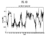
- FIG. 6 is a view showing change in power of the first and second battery racks when regulating a frequency using the first and second battery racks, according to an embodiment of the present invention.
Landscapes
- Engineering & Computer Science (AREA)
- Power Engineering (AREA)
- Business, Economics & Management (AREA)
- Emergency Management (AREA)
- Charge And Discharge Circuits For Batteries Or The Like (AREA)
- Supply And Distribution Of Alternating Current (AREA)
Applications Claiming Priority (1)
| Application Number | Priority Date | Filing Date | Title |
|---|---|---|---|
| KR1020140025368A KR102234703B1 (ko) | 2014-03-04 | 2014-03-04 | 에너지 저장 시스템 및 이의 제어 방법 |
Publications (2)
| Publication Number | Publication Date |
|---|---|
| EP2916417A1 true EP2916417A1 (fr) | 2015-09-09 |
| EP2916417B1 EP2916417B1 (fr) | 2017-11-08 |
Family
ID=52595163
Family Applications (1)
| Application Number | Title | Priority Date | Filing Date |
|---|---|---|---|
| EP15157048.8A Active EP2916417B1 (fr) | 2014-03-04 | 2015-02-27 | Système de stockage d'énergie et son procédé de contrôle |
Country Status (4)
| Country | Link |
|---|---|
| US (1) | US10763682B2 (fr) |
| EP (1) | EP2916417B1 (fr) |
| KR (1) | KR102234703B1 (fr) |
| CN (1) | CN104901324B (fr) |
Cited By (5)
| Publication number | Priority date | Publication date | Assignee | Title |
|---|---|---|---|---|
| EP3148042A1 (fr) * | 2015-09-24 | 2017-03-29 | Samsung SDI Co., Ltd. | Alimentation électrique ne pouvant être interrompue |
| WO2018146174A1 (fr) * | 2017-02-09 | 2018-08-16 | Abb Schweiz Ag | Surveillance d'une batterie ups |
| EP3148037B1 (fr) * | 2015-09-24 | 2019-01-02 | Samsung SDI Co., Ltd. | Systeme de stockage d'energie |
| CN113364046A (zh) * | 2021-05-30 | 2021-09-07 | 国网福建省电力有限公司 | 一种支撑电网频率的储能电站群协调控制方法 |
| EP4303601A4 (fr) * | 2021-03-25 | 2024-07-10 | Huawei Digital Power Technologies Co., Ltd. | Procédé de commande de système de stockage d'énergie et système de stockage d'énergie |
Families Citing this family (20)
| Publication number | Priority date | Publication date | Assignee | Title |
|---|---|---|---|---|
| US9899864B2 (en) | 2015-04-10 | 2018-02-20 | Enovate Medical, Llc | Bidirectional power converter |
| CN107230994B (zh) * | 2016-03-23 | 2019-09-27 | 北京睿能世纪科技有限公司 | 一种控制储能系统出力的方法及装置 |
| US10141776B2 (en) * | 2016-06-20 | 2018-11-27 | General Electric Company | Distribution of power commands in an energy storage system |
| CN106532893B (zh) * | 2016-11-21 | 2019-02-01 | 珠海格力电器股份有限公司 | 光伏空调器、电池管理系统及其控制方法 |
| JP2018166967A (ja) * | 2017-03-30 | 2018-11-01 | キヤノンメディカルシステムズ株式会社 | 医用画像診断装置 |
| KR102491098B1 (ko) * | 2017-07-04 | 2023-01-20 | 주식회사 케이티 | 신재생 발전소에서 발생되는 전력의 출력 변동을 제어하는 시스템, 에너지 저장 장치 및 방법 |
| US11594883B2 (en) * | 2018-01-23 | 2023-02-28 | Tdk Corporation | Direct current power supplying system |
| TWI672843B (zh) * | 2018-05-23 | 2019-09-21 | 廣達電腦股份有限公司 | 電池裝置及其操作方法 |
| KR102110140B1 (ko) * | 2018-12-28 | 2020-05-13 | 군산대학교산학협력단 | 다중 배터리 기반의 독립형 신재생에너지 시스템 |
| US11509153B2 (en) * | 2019-07-18 | 2022-11-22 | Save The Planet Co., Ltd. | Charge/discharge control method for storage system and charge/discharge control device |
| KR102202878B1 (ko) * | 2019-10-29 | 2021-01-15 | 한국생산기술연구원 | 전력선 통신 기반 전기자전거 제어 시스템 및 이의 제어 방법 |
| KR102837099B1 (ko) * | 2020-02-03 | 2025-07-22 | 주식회사 엘지에너지솔루션 | 배터리 랙의 개별 방전 시스템 및 방법 |
| WO2021251512A1 (fr) * | 2020-06-09 | 2021-12-16 | Battery R&D Association Of Korea | Système de charge/décharge hybride |
| AU2021300164B2 (en) * | 2020-06-29 | 2024-06-20 | E2 Ip Holding Llc | Providing rapid threshold amount of power to customer load during transfer between primary and secondary power supplies |
| EP4176505A1 (fr) * | 2020-07-01 | 2023-05-10 | Vestas Wind Systems A/S | Test de batterie en fonctionnement |
| CN112117807B (zh) * | 2020-09-25 | 2022-11-15 | 阳光电源股份有限公司 | 储能dc/dc变换模块及其控制器和储能功率变换系统 |
| KR102566354B1 (ko) * | 2021-03-25 | 2023-08-17 | 주식회사 이엘티 | 배터리 화재 예방시스템이 적용된 dc 배전 컨테이너형 하우스 |
| WO2022264303A1 (fr) * | 2021-06-16 | 2022-12-22 | 東芝三菱電機産業システム株式会社 | Dispositif d'alimentation sans interruption |
| KR20230073473A (ko) | 2021-11-19 | 2023-05-26 | 주식회사 엘지에너지솔루션 | 재사용 배터리를 포함하는 에너지 저장 시스템 및 에너지 저장 시스템 운영 방법 |
| US12452799B2 (en) | 2022-02-28 | 2025-10-21 | Samsung Electronics Co., Ltd. | Electronic apparatus and controlling method thereof |
Citations (2)
| Publication number | Priority date | Publication date | Assignee | Title |
|---|---|---|---|---|
| US20120091967A1 (en) * | 2010-10-14 | 2012-04-19 | Shinya Kawamoto | Power stabilization system and power stabilizing method |
| WO2013103011A1 (fr) * | 2012-01-06 | 2013-07-11 | 株式会社日立製作所 | Système de stabilisation de réseau électrique et procédé de stabilisation de réseau électrique |
Family Cites Families (7)
| Publication number | Priority date | Publication date | Assignee | Title |
|---|---|---|---|---|
| JP2004357481A (ja) * | 2003-05-30 | 2004-12-16 | Sanyo Electric Co Ltd | 複数のバッテリを充電する方法と放電する方法 |
| EP2293406B1 (fr) | 2009-09-07 | 2015-08-05 | ABB Research Ltd. | Systèmes de stockage d'énergie |
| WO2012043134A1 (fr) * | 2010-09-30 | 2012-04-05 | 三洋電機株式会社 | Dispositif de commande de charge/décharge de batterie rechargeable et procédé de commande de charge/décharge de batterie rechargeable |
| KR101147202B1 (ko) * | 2010-10-13 | 2012-05-25 | 삼성에스디아이 주식회사 | 전력 저장 장치 |
| KR20120110478A (ko) | 2011-03-29 | 2012-10-10 | (주)인텍에프에이 | 신재생에너지 발전용 에너지 저장 시스템 및 그 제어방법 |
| KR101493355B1 (ko) | 2011-12-26 | 2015-02-13 | 주식회사 케이티 | 에너지 저장 장치의 soc 보정 방법 및 이를 이용하는 soc 보정 시스템 |
| KR101769776B1 (ko) | 2012-03-08 | 2017-08-21 | 에스케이이노베이션 주식회사 | 주파수 제어 시스템 및 방법 |
-
2014
- 2014-03-04 KR KR1020140025368A patent/KR102234703B1/ko active Active
-
2015
- 2015-02-10 US US14/618,954 patent/US10763682B2/en active Active
- 2015-02-27 EP EP15157048.8A patent/EP2916417B1/fr active Active
- 2015-03-03 CN CN201510094844.1A patent/CN104901324B/zh active Active
Patent Citations (3)
| Publication number | Priority date | Publication date | Assignee | Title |
|---|---|---|---|---|
| US20120091967A1 (en) * | 2010-10-14 | 2012-04-19 | Shinya Kawamoto | Power stabilization system and power stabilizing method |
| WO2013103011A1 (fr) * | 2012-01-06 | 2013-07-11 | 株式会社日立製作所 | Système de stabilisation de réseau électrique et procédé de stabilisation de réseau électrique |
| EP2802053A1 (fr) * | 2012-01-06 | 2014-11-12 | Hitachi, Ltd. | Système de stabilisation de réseau électrique et procédé de stabilisation de réseau électrique |
Cited By (6)
| Publication number | Priority date | Publication date | Assignee | Title |
|---|---|---|---|---|
| EP3148042A1 (fr) * | 2015-09-24 | 2017-03-29 | Samsung SDI Co., Ltd. | Alimentation électrique ne pouvant être interrompue |
| EP3148037B1 (fr) * | 2015-09-24 | 2019-01-02 | Samsung SDI Co., Ltd. | Systeme de stockage d'energie |
| US10284009B2 (en) | 2015-09-24 | 2019-05-07 | Samsung Sdi Co., Ltd. | Uninterruptible power supply |
| WO2018146174A1 (fr) * | 2017-02-09 | 2018-08-16 | Abb Schweiz Ag | Surveillance d'une batterie ups |
| EP4303601A4 (fr) * | 2021-03-25 | 2024-07-10 | Huawei Digital Power Technologies Co., Ltd. | Procédé de commande de système de stockage d'énergie et système de stockage d'énergie |
| CN113364046A (zh) * | 2021-05-30 | 2021-09-07 | 国网福建省电力有限公司 | 一种支撑电网频率的储能电站群协调控制方法 |
Also Published As
| Publication number | Publication date |
|---|---|
| EP2916417B1 (fr) | 2017-11-08 |
| KR102234703B1 (ko) | 2021-04-01 |
| US10763682B2 (en) | 2020-09-01 |
| CN104901324B (zh) | 2020-07-10 |
| CN104901324A (zh) | 2015-09-09 |
| KR20150103840A (ko) | 2015-09-14 |
| US20150255999A1 (en) | 2015-09-10 |
Similar Documents
| Publication | Publication Date | Title |
|---|---|---|
| EP2916417B1 (fr) | Système de stockage d'énergie et son procédé de contrôle | |
| EP2884575B1 (fr) | Système de batterie et procédé de connexion de module de batterie à un support de batterie | |
| EP2566007B1 (fr) | Procédé et dispositif d'équilibrage de cellule | |
| KR101084215B1 (ko) | 에너지 저장 시스템 및 이의 제어 방법 | |
| US8854004B2 (en) | Energy storage system and controlling method thereof | |
| US11063447B2 (en) | Battery pack and energy storage system comprising same | |
| KR101364094B1 (ko) | 배터리 시스템 및 이를 포함하는 에너지 저장 시스템 | |
| KR101084216B1 (ko) | 에너지 저장 시스템 및 이의 제어 방법 | |
| US9071056B2 (en) | Apparatus and method for managing battery cell, and energy storage system | |
| KR101193168B1 (ko) | 전력 저장 시스템, 그 제어방법 및 이를 실행시키기 위한 프로그램을 저장한 기록매체 | |
| KR102234290B1 (ko) | 에너지 저장 시스템 및 그의 구동방법 | |
| EP3148037A1 (fr) | Systeme de stockage d'energie | |
| US20150222117A1 (en) | Battery tray, battery rack, energy system, and method of operating the battery tray | |
| EP2574075A2 (fr) | Système de batteries | |
| KR20150081731A (ko) | 배터리 팩, 배터리 팩을 포함하는 에너지 저장 시스템, 배터리 팩의 작동 방법 | |
| KR20120111406A (ko) | 배터리 시스템 및 이를 포함하는 에너지 저장 시스템 | |
| KR20150085383A (ko) | 배터리 시스템 및 배터리 시스템을 포함하는 에너지 저장 시스템 | |
| KR20130049706A (ko) | 배터리 관리 장치, 배터리 셀 밸런싱 방법, 및 전력 저장 시스템 | |
| KR20170036328A (ko) | 무정전 전원 공급장치 | |
| KR101698267B1 (ko) | 에너지 저장 시스템의 제어 방법 |
Legal Events
| Date | Code | Title | Description |
|---|---|---|---|
| PUAI | Public reference made under article 153(3) epc to a published international application that has entered the european phase |
Free format text: ORIGINAL CODE: 0009012 |
|
| AK | Designated contracting states |
Kind code of ref document: A1 Designated state(s): AL AT BE BG CH CY CZ DE DK EE ES FI FR GB GR HR HU IE IS IT LI LT LU LV MC MK MT NL NO PL PT RO RS SE SI SK SM TR |
|
| AX | Request for extension of the european patent |
Extension state: BA ME |
|
| 17P | Request for examination filed |
Effective date: 20160309 |
|
| RBV | Designated contracting states (corrected) |
Designated state(s): AL AT BE BG CH CY CZ DE DK EE ES FI FR GB GR HR HU IE IS IT LI LT LU LV MC MK MT NL NO PL PT RO RS SE SI SK SM TR |
|
| 17Q | First examination report despatched |
Effective date: 20160420 |
|
| GRAP | Despatch of communication of intention to grant a patent |
Free format text: ORIGINAL CODE: EPIDOSNIGR1 |
|
| STAA | Information on the status of an ep patent application or granted ep patent |
Free format text: STATUS: GRANT OF PATENT IS INTENDED |
|
| INTG | Intention to grant announced |
Effective date: 20170523 |
|
| GRAS | Grant fee paid |
Free format text: ORIGINAL CODE: EPIDOSNIGR3 |
|
| GRAA | (expected) grant |
Free format text: ORIGINAL CODE: 0009210 |
|
| STAA | Information on the status of an ep patent application or granted ep patent |
Free format text: STATUS: THE PATENT HAS BEEN GRANTED |
|
| GRAT | Correction requested after decision to grant or after decision to maintain patent in amended form |
Free format text: ORIGINAL CODE: EPIDOSNCDEC |
|
| AK | Designated contracting states |
Kind code of ref document: B1 Designated state(s): AL AT BE BG CH CY CZ DE DK EE ES FI FR GB GR HR HU IE IS IT LI LT LU LV MC MK MT NL NO PL PT RO RS SE SI SK SM TR |
|
| REG | Reference to a national code |
Ref country code: GB Ref legal event code: FG4D |
|
| REG | Reference to a national code |
Ref country code: CH Ref legal event code: EP Ref country code: AT Ref legal event code: REF Ref document number: 945038 Country of ref document: AT Kind code of ref document: T Effective date: 20171115 |
|
| REG | Reference to a national code |
Ref country code: IE Ref legal event code: FG4D |
|
| REG | Reference to a national code |
Ref country code: DE Ref legal event code: R096 Ref document number: 602015005777 Country of ref document: DE |
|
| REG | Reference to a national code |
Ref country code: FR Ref legal event code: PLFP Year of fee payment: 4 |
|
| REG | Reference to a national code |
Ref country code: NL Ref legal event code: MP Effective date: 20171108 |
|
| REG | Reference to a national code |
Ref country code: LT Ref legal event code: MG4D |
|
| REG | Reference to a national code |
Ref country code: AT Ref legal event code: MK05 Ref document number: 945038 Country of ref document: AT Kind code of ref document: T Effective date: 20171108 |
|
| PG25 | Lapsed in a contracting state [announced via postgrant information from national office to epo] |
Ref country code: SE Free format text: LAPSE BECAUSE OF FAILURE TO SUBMIT A TRANSLATION OF THE DESCRIPTION OR TO PAY THE FEE WITHIN THE PRESCRIBED TIME-LIMIT Effective date: 20171108 Ref country code: LT Free format text: LAPSE BECAUSE OF FAILURE TO SUBMIT A TRANSLATION OF THE DESCRIPTION OR TO PAY THE FEE WITHIN THE PRESCRIBED TIME-LIMIT Effective date: 20171108 Ref country code: NL Free format text: LAPSE BECAUSE OF FAILURE TO SUBMIT A TRANSLATION OF THE DESCRIPTION OR TO PAY THE FEE WITHIN THE PRESCRIBED TIME-LIMIT Effective date: 20171108 Ref country code: FI Free format text: LAPSE BECAUSE OF FAILURE TO SUBMIT A TRANSLATION OF THE DESCRIPTION OR TO PAY THE FEE WITHIN THE PRESCRIBED TIME-LIMIT Effective date: 20171108 Ref country code: ES Free format text: LAPSE BECAUSE OF FAILURE TO SUBMIT A TRANSLATION OF THE DESCRIPTION OR TO PAY THE FEE WITHIN THE PRESCRIBED TIME-LIMIT Effective date: 20171108 Ref country code: NO Free format text: LAPSE BECAUSE OF FAILURE TO SUBMIT A TRANSLATION OF THE DESCRIPTION OR TO PAY THE FEE WITHIN THE PRESCRIBED TIME-LIMIT Effective date: 20180208 |
|
| PG25 | Lapsed in a contracting state [announced via postgrant information from national office to epo] |
Ref country code: LV Free format text: LAPSE BECAUSE OF FAILURE TO SUBMIT A TRANSLATION OF THE DESCRIPTION OR TO PAY THE FEE WITHIN THE PRESCRIBED TIME-LIMIT Effective date: 20171108 Ref country code: HR Free format text: LAPSE BECAUSE OF FAILURE TO SUBMIT A TRANSLATION OF THE DESCRIPTION OR TO PAY THE FEE WITHIN THE PRESCRIBED TIME-LIMIT Effective date: 20171108 Ref country code: IS Free format text: LAPSE BECAUSE OF FAILURE TO SUBMIT A TRANSLATION OF THE DESCRIPTION OR TO PAY THE FEE WITHIN THE PRESCRIBED TIME-LIMIT Effective date: 20180308 Ref country code: GR Free format text: LAPSE BECAUSE OF FAILURE TO SUBMIT A TRANSLATION OF THE DESCRIPTION OR TO PAY THE FEE WITHIN THE PRESCRIBED TIME-LIMIT Effective date: 20180209 Ref country code: RS Free format text: LAPSE BECAUSE OF FAILURE TO SUBMIT A TRANSLATION OF THE DESCRIPTION OR TO PAY THE FEE WITHIN THE PRESCRIBED TIME-LIMIT Effective date: 20171108 Ref country code: AT Free format text: LAPSE BECAUSE OF FAILURE TO SUBMIT A TRANSLATION OF THE DESCRIPTION OR TO PAY THE FEE WITHIN THE PRESCRIBED TIME-LIMIT Effective date: 20171108 Ref country code: BG Free format text: LAPSE BECAUSE OF FAILURE TO SUBMIT A TRANSLATION OF THE DESCRIPTION OR TO PAY THE FEE WITHIN THE PRESCRIBED TIME-LIMIT Effective date: 20180208 |
|
| PG25 | Lapsed in a contracting state [announced via postgrant information from national office to epo] |
Ref country code: CZ Free format text: LAPSE BECAUSE OF FAILURE TO SUBMIT A TRANSLATION OF THE DESCRIPTION OR TO PAY THE FEE WITHIN THE PRESCRIBED TIME-LIMIT Effective date: 20171108 Ref country code: CY Free format text: LAPSE BECAUSE OF FAILURE TO SUBMIT A TRANSLATION OF THE DESCRIPTION OR TO PAY THE FEE WITHIN THE PRESCRIBED TIME-LIMIT Effective date: 20171108 Ref country code: EE Free format text: LAPSE BECAUSE OF FAILURE TO SUBMIT A TRANSLATION OF THE DESCRIPTION OR TO PAY THE FEE WITHIN THE PRESCRIBED TIME-LIMIT Effective date: 20171108 Ref country code: DK Free format text: LAPSE BECAUSE OF FAILURE TO SUBMIT A TRANSLATION OF THE DESCRIPTION OR TO PAY THE FEE WITHIN THE PRESCRIBED TIME-LIMIT Effective date: 20171108 Ref country code: SK Free format text: LAPSE BECAUSE OF FAILURE TO SUBMIT A TRANSLATION OF THE DESCRIPTION OR TO PAY THE FEE WITHIN THE PRESCRIBED TIME-LIMIT Effective date: 20171108 |
|
| REG | Reference to a national code |
Ref country code: DE Ref legal event code: R097 Ref document number: 602015005777 Country of ref document: DE |
|
| PG25 | Lapsed in a contracting state [announced via postgrant information from national office to epo] |
Ref country code: RO Free format text: LAPSE BECAUSE OF FAILURE TO SUBMIT A TRANSLATION OF THE DESCRIPTION OR TO PAY THE FEE WITHIN THE PRESCRIBED TIME-LIMIT Effective date: 20171108 Ref country code: SM Free format text: LAPSE BECAUSE OF FAILURE TO SUBMIT A TRANSLATION OF THE DESCRIPTION OR TO PAY THE FEE WITHIN THE PRESCRIBED TIME-LIMIT Effective date: 20171108 Ref country code: IT Free format text: LAPSE BECAUSE OF FAILURE TO SUBMIT A TRANSLATION OF THE DESCRIPTION OR TO PAY THE FEE WITHIN THE PRESCRIBED TIME-LIMIT Effective date: 20171108 Ref country code: PL Free format text: LAPSE BECAUSE OF FAILURE TO SUBMIT A TRANSLATION OF THE DESCRIPTION OR TO PAY THE FEE WITHIN THE PRESCRIBED TIME-LIMIT Effective date: 20171108 |
|
| PLBE | No opposition filed within time limit |
Free format text: ORIGINAL CODE: 0009261 |
|
| REG | Reference to a national code |
Ref country code: CH Ref legal event code: PL |
|
| STAA | Information on the status of an ep patent application or granted ep patent |
Free format text: STATUS: NO OPPOSITION FILED WITHIN TIME LIMIT |
|
| PG25 | Lapsed in a contracting state [announced via postgrant information from national office to epo] |
Ref country code: MC Free format text: LAPSE BECAUSE OF FAILURE TO SUBMIT A TRANSLATION OF THE DESCRIPTION OR TO PAY THE FEE WITHIN THE PRESCRIBED TIME-LIMIT Effective date: 20171108 |
|
| 26N | No opposition filed |
Effective date: 20180809 |
|
| REG | Reference to a national code |
Ref country code: IE Ref legal event code: MM4A |
|
| REG | Reference to a national code |
Ref country code: BE Ref legal event code: MM Effective date: 20180228 |
|
| PG25 | Lapsed in a contracting state [announced via postgrant information from national office to epo] |
Ref country code: LI Free format text: LAPSE BECAUSE OF NON-PAYMENT OF DUE FEES Effective date: 20180228 Ref country code: LU Free format text: LAPSE BECAUSE OF NON-PAYMENT OF DUE FEES Effective date: 20180227 Ref country code: CH Free format text: LAPSE BECAUSE OF NON-PAYMENT OF DUE FEES Effective date: 20180228 Ref country code: SI Free format text: LAPSE BECAUSE OF FAILURE TO SUBMIT A TRANSLATION OF THE DESCRIPTION OR TO PAY THE FEE WITHIN THE PRESCRIBED TIME-LIMIT Effective date: 20171108 |
|
| PG25 | Lapsed in a contracting state [announced via postgrant information from national office to epo] |
Ref country code: IE Free format text: LAPSE BECAUSE OF NON-PAYMENT OF DUE FEES Effective date: 20180227 |
|
| PG25 | Lapsed in a contracting state [announced via postgrant information from national office to epo] |
Ref country code: BE Free format text: LAPSE BECAUSE OF NON-PAYMENT OF DUE FEES Effective date: 20180228 |
|
| PG25 | Lapsed in a contracting state [announced via postgrant information from national office to epo] |
Ref country code: MT Free format text: LAPSE BECAUSE OF NON-PAYMENT OF DUE FEES Effective date: 20180227 |
|
| PG25 | Lapsed in a contracting state [announced via postgrant information from national office to epo] |
Ref country code: TR Free format text: LAPSE BECAUSE OF FAILURE TO SUBMIT A TRANSLATION OF THE DESCRIPTION OR TO PAY THE FEE WITHIN THE PRESCRIBED TIME-LIMIT Effective date: 20171108 |
|
| PG25 | Lapsed in a contracting state [announced via postgrant information from national office to epo] |
Ref country code: PT Free format text: LAPSE BECAUSE OF FAILURE TO SUBMIT A TRANSLATION OF THE DESCRIPTION OR TO PAY THE FEE WITHIN THE PRESCRIBED TIME-LIMIT Effective date: 20171108 |
|
| PG25 | Lapsed in a contracting state [announced via postgrant information from national office to epo] |
Ref country code: MK Free format text: LAPSE BECAUSE OF NON-PAYMENT OF DUE FEES Effective date: 20171108 Ref country code: HU Free format text: LAPSE BECAUSE OF FAILURE TO SUBMIT A TRANSLATION OF THE DESCRIPTION OR TO PAY THE FEE WITHIN THE PRESCRIBED TIME-LIMIT; INVALID AB INITIO Effective date: 20150227 |
|
| PG25 | Lapsed in a contracting state [announced via postgrant information from national office to epo] |
Ref country code: AL Free format text: LAPSE BECAUSE OF FAILURE TO SUBMIT A TRANSLATION OF THE DESCRIPTION OR TO PAY THE FEE WITHIN THE PRESCRIBED TIME-LIMIT Effective date: 20171108 |
|
| P01 | Opt-out of the competence of the unified patent court (upc) registered |
Effective date: 20230528 |
|
| PGFP | Annual fee paid to national office [announced via postgrant information from national office to epo] |
Ref country code: GB Payment date: 20260128 Year of fee payment: 12 |
|
| PGFP | Annual fee paid to national office [announced via postgrant information from national office to epo] |
Ref country code: DE Payment date: 20260128 Year of fee payment: 12 |
|
| PGFP | Annual fee paid to national office [announced via postgrant information from national office to epo] |
Ref country code: FR Payment date: 20260121 Year of fee payment: 12 |