EP2803256A1 - Moissonneuse dotée d'un réglage de la vitesse de propulsion anticipé - Google Patents
Moissonneuse dotée d'un réglage de la vitesse de propulsion anticipé Download PDFInfo
- Publication number
- EP2803256A1 EP2803256A1 EP14165608.2A EP14165608A EP2803256A1 EP 2803256 A1 EP2803256 A1 EP 2803256A1 EP 14165608 A EP14165608 A EP 14165608A EP 2803256 A1 EP2803256 A1 EP 2803256A1
- Authority
- EP
- European Patent Office
- Prior art keywords
- harvester
- flow rate
- mass flow
- crop
- value
- Prior art date
- Legal status (The legal status is an assumption and is not a legal conclusion. Google has not performed a legal analysis and makes no representation as to the accuracy of the status listed.)
- Granted
Links
Images


Classifications
-
- A—HUMAN NECESSITIES
- A01—AGRICULTURE; FORESTRY; ANIMAL HUSBANDRY; HUNTING; TRAPPING; FISHING
- A01D—HARVESTING; MOWING
- A01D34/00—Mowers; Mowing apparatus of harvesters
- A01D34/006—Control or measuring arrangements
-
- A—HUMAN NECESSITIES
- A01—AGRICULTURE; FORESTRY; ANIMAL HUSBANDRY; HUNTING; TRAPPING; FISHING
- A01D—HARVESTING; MOWING
- A01D41/00—Combines, i.e. harvesters or mowers combined with threshing devices
- A01D41/12—Details of combines
- A01D41/127—Control or measuring arrangements specially adapted for combines
-
- A—HUMAN NECESSITIES
- A01—AGRICULTURE; FORESTRY; ANIMAL HUSBANDRY; HUNTING; TRAPPING; FISHING
- A01D—HARVESTING; MOWING
- A01D41/00—Combines, i.e. harvesters or mowers combined with threshing devices
- A01D41/12—Details of combines
- A01D41/127—Control or measuring arrangements specially adapted for combines
- A01D41/1271—Control or measuring arrangements specially adapted for combines for measuring crop flow
-
- A—HUMAN NECESSITIES
- A01—AGRICULTURE; FORESTRY; ANIMAL HUSBANDRY; HUNTING; TRAPPING; FISHING
- A01D—HARVESTING; MOWING
- A01D41/00—Combines, i.e. harvesters or mowers combined with threshing devices
- A01D41/12—Details of combines
- A01D41/127—Control or measuring arrangements specially adapted for combines
- A01D41/1274—Control or measuring arrangements specially adapted for combines for drives
Definitions
- the invention relates to a harvesting machine, the propulsion speed of which is regulated by means of an arrangement for the predictive, non-contact detection of a standing before the harvester crop stock in advance in terms of compliance with a predetermined mass flow rate.
- the signal also provides information about the density of the plant population, because in incomplete stocks on the ground penetrating rays lead to greater variations in the maturity and thus the evaluated distances as dense stocks that provide more homogeneous range values.
- a radar rangefinder is used whose rays penetrate the plant population and enable the creation of a soil profile, which is used in conjunction with the measured values of the laser rangefinder to determine the plant height.
- the intensities and transit times of radar waves reflected by plants are recorded to evaluate the geometric population density (ie the volume of plants per unit volume or area of field), the moisture of the plants and the bulk density of the plants.
- the DE 101 30 665 A1 describes a combine with a laser rangefinder, which oscillates around the vertical axis and scans the crop in front of the combine successively in the lateral direction.
- the transit times of the reflected waves are detected by a receiver, which determines the vertical surface of the crop stock based on the transit times and the geometric arrangement of the rangefinder.
- the volumetric density (degree of space filling) of the crop is estimated on the basis of the intensity of the reflected waves.
- a multiplication of the volume density with the vertical area and the velocity gives an expected throughput rate measured in units of volume per time.
- Another moisture sensor looking ahead to the inventory, determines the moisture content of the crop to determine the mass density and, ultimately, the throughput rate to determine the expected mass flow rate.
- This mass flow rate serves for the automatic, anticipatory determination of the propulsion speed.
- the throughput rate can be calibrated on the basis of a measured value of a good throughput sensor which is sensed on board the combine harvester and detects, for example, the drive torque of a threshing drum.
- the DE 10 2011 085 380 A1 describes another harvesting machine with forward-looking on the plant stock looking, working with electromagnetic waves sensors from whose signals statistical parameters are derived, which are compared with recorded by the harvester crop sensors cooperating signals compared to automatically correlations between the statistical parameters and the crop characteristics determine and then use the signals of the predictive sensors, taking into account the evaluated context for the automatic control of the harvester.
- the crop parameters include stock density and moisture.
- the predictive sensors can, for. B. detect the intensities and polarizations of the reflected waves.
- DE 101 30 665 A1 and DE 10 2011 085 380 A1 also take into account sensor values obtained on board the harvester, in order to obtain the signals from the Subsequently, the quantities obtained from non-contact sensors can be more accurately evaluated on the basis of learned relationships.
- a correction table is generated which corrects the flow rates determined by the electromagnetic sensor on the basis of the throughputs measured on board.
- the DE 10 2011 085 380 A1 determines correlations between statistical parameters of the crop and the recorded throughputs.
- the sensor values obtained on board the harvesting machine are thus indirectly used to first convert the values of the non-contact sensors into a more accurate material throughput, which then again serves as the only control input for the speed control.
- the speed control function relies on absolute readings from non-contact sensors, but in practice this accuracy is not always sufficient to achieve satisfactory results.
- the methods under steady state conditions are not always accurate and have long reaction times due to the required evaluation times of the statistical parameters.
- the object underlying the invention is seen to provide a harvester, in which the above-mentioned disadvantages are not present or to a lesser extent.
- a harvester includes propulsion means for moving the harvester at a speed v across a field.
- a suitable arrangement is for the continuous, proactive, non-contact detection of a harvester crop standing in front of the harvester and for providing data regarding an expected mass flow rate in the harvester.
- a controller is configured to automatically control the advancing speed of the harvester in consideration of the expected mass flow rate calculated using the data of said assembly to maintain a desired value of the mass flow rate.
- a sensor is used to detect one of the actual Mass flow rate of harvester dependent size. The controller is configured to compare the output value of the sensor with a value that depends on the expected mass flow rate and to use the result of the comparison continuously as a feedback value for controlling the feed rate.
- mass flow rate data are anticipated by the aforementioned arrangement for predictive, non-contact detection of a harvester crop standing in front of the harvester
- a representative of the mass flow rate is additionally sensed on board the harvester and compared to a value that is is a value expected by the controller in terms of mass flow. Any deviations between the measured value of the sensor and the expected value are used as feedback value for the propulsion speed setting.
- This approach is particularly useful for arrangements that can clearly see changes in crop throughput, but not the absolute values of crop throughput.
- the latter are considered according to the present invention by the sensor for detecting the mass-flow rate of the harvester dependent variable and its comparison with the expected value as well as the feedback of the result of the comparison to the velocity determination.
- the arrangement for the predictive, non-contact detection of the harvester standing in front of the harvester and for providing data on an expected mass flow rate in the harvester is preferably a rangefinder with a transmitter for successively loading a standing before the harvester crop inventory with electromagnetic waves, a receiver for receiving of waves reflected from the crop stock and an evaluation unit which uses the durations and / or amplitudes of the received waves to calculate data against which an expected mass throughput in the harvester is evaluable.
- Other embodiments of the mentioned arrangement are conceivable, in particular cameras with image processing systems.
- the range finder is a radar sensor in which the electromagnetic waves radiated by the transmitter are horizontally and / or vertically polarized radar waves and the receiver receives from the plant population reflected, vertically polarized radar waves and / or horizontally polarized radar waves.
- This radar waves can a single Frequency or different frequencies are used.
- the evaluation unit evaluates in particular the temporal derivation of the space filling factor of the plant population with dry matter and water as well as the recorded volume.
- any other rangefinder may be used, for example in the visible or infrared laser rangefinder and the like.
- the senor detects a pressure in a hydraulic cylinder which adjusts a belt variator for driving an axial threshing and / or separating rotor.
- the sensor can also detect any other variables, such as the drive torque of a feeder or a tangential threshing drum or the layer thickness in the feeder and the moisture of the crop.
- the control expediently takes into account the time delay between the generation of the expected throughput-dependent value and the detection by the sensor.
- the value can be delayed (stored) and supplied to a comparator only when the plants covered by the rangefinder interact with the sensor.
- the controller may convert the result of the comparison into a mass flow rate subtracted from a mass flow rate calculated from the data of said array.
- the controller may further include a model of the harvester that is used to determine the expected throughput dependent value that is used in addition to specifying the propulsion speed.
- the value dependent on the expected throughput is predicted model-based.
- the model receives the result of the comparison between the sensor output value and the mass flow rate dependent value as an input value and is dynamically adjusted to the actual circumstances. Using the actual measured values, the estimation and prediction of the model is constantly refined and adjusted.
- the arrangement according to the invention can be used on self-propelled harvesters or harvesters pulled or mounted by a vehicle, for example combine harvesters, balers or forage harvesters.
- FIG. 1 shows an agricultural combine 10 having a supporting structure 12 provided with wheels 14 engaged with the ground.
- the combine harvester 10 is illustrated with wheels, it could be provided with two or four caterpillars.
- a header 16 is used to harvest crop material and feeds it to a feeder 18.
- the inclined conveyor 18 includes a conveyor to feed the harvested crop to a beater 20.
- the guide drum 20 leads the goods up through an inlet transition section 22 and a rotatable, arranged for threshing and separating crop processing device 24 to.
- the crop processing device 24 shown is arranged axially in the combine harvester, but it could also be arranged in other orientations relative to the longitudinal axis of the combine 10.
- the present invention is described in terms of a crop processor 24 having a rotor, it could also be used on a combine 10 having a conventional transversely disposed threshing drum cooperating with a concave.
- the crop processing device 24 threshes and separates the harvested good.
- the grain and chaff fall through grates at the bottom of the cropper 24 into a cleaning system 26.
- the cleaning system 26 removes the chaff and feeds the clean grain to a clean grain elevator (not shown).
- the clean grain elevator deposits the grain in a grain tank 28.
- the clean grain in the grain tank 28 may be fed by a discharge auger 30 to a truck or trailer.
- broken straw cleared of the grain is fed from the crop processor 24 through an outlet 32 to an ejection drum 34.
- the ejection drum 34 ejects the straw again at the back of the combine 10. It should be noted that the ejection drum 34 could also feed the grain freed directly to a straw chopper.
- the operation of the combine 10 is controlled from an operator's cab 35.
- the crop processing device 24 comprises a cylindrical rotor housing 36 and a rotatable rotor 37 arranged in the rotor housing 36.
- the front part of the rotor 37 and the rotor housing 36 define a charging section 38. Downstream of the charging section 38 are a threshing section 39, a separating section 40 and an outlet section 41
- the rotor 37 is provided in the loading section 38 with a conical rotor drum having helical loading elements for engaging in good received from the guide drum 20 and the inlet transition section 22.
- the threshing section 39 Immediately downstream of the loading section 38 is the threshing section 39.
- the rotor 37 has a cylindrical rotor drum provided with a number of threshing elements for threshing the crop obtained from the loading section 38.
- the separating section 40 Downstream of the threshing section 39 is the separating section 40, in which the grain still contained in the threshed crop is released and falls through a bottom-side grate in the rotor housing 36 into the cleaning system 28.
- the separating section 40 merges into the outlet section 41, in which the grain-free material (straw) is ejected from the crop processing device 24.
- the front wheels 14 of the combine harvester 10 are driven by a hydrostatic transmission 50 as shown in FIG.
- the hydrostatic transmission 50 is driven in a conventional manner by an internal combustion engine, not shown.
- the hydrostatic transmission 50 in turn drives a manual transmission 52.
- Two driving shafts 54 extend outwardly from the manual transmission 52 and drive end drives 56 of the front wheels 14.
- the hydrostatic transmission 50 includes a pump unit and a motor unit.
- the pump unit and / or the motor unit are equipped with adjustable swash plates.
- the adjustable swash plates control the output speed of the transmission 50 and its direction of rotation.
- Electromagnetically controlled control valves control the positions of the swash plates.
- the steerable rear wheels 14 may also be driven by wheel motors directly attached to the wheels 14. The speed of the wheel motors may be controlled by the flow rate control system described below.
- An adjustable drive 60 with variable torque drives the rotor 37.
- the variable displacement drive 60 is a belt drive that includes a variable diameter driving pulley, not shown, and a variable diameter driven pulley.
- a belt 64 extends between the driving pulley and the driven pulley 62 for rotational performance transferred to. Hydraulic cylinders control the diameter of the pulleys.
- the hydraulic cylinder 66 is coupled to the driven pulley 62 and moves the end plates 68 of the pulley 62 inwardly and outwardly, respectively, to control the effective diameter of the pulley 62 against the belt 64.
- the effective speed of the driven pulley 62 is changed.
- hydraulic line 70 hydraulic fluid pressurized by a valve assembly 72 is supplied to the hydraulic cylinder 66.
- the rotor 37 is driven by the variable diameter pulleys at a constant, selected rotor speed.
- the torque transmitted by the belt 64 and the pulleys varies with the mass flow rate of the crop.
- An electronic controller 80 controls the propulsion speed v of the combine 10. That is, the electronic controller 80 adjusts the forward speed (harvesting speed) of the combine 10 by adjusting the position of the swash plates of the hydrostatic transmission 50 by controlling the operation of the electromagnetically actuated control valves Line 82 is controlled.
- the controller 80 receives a current hydraulic pressure signal from a hydraulic pressure sensor 86 through the line 84.
- the hydraulic pressure sensor 86 senses the hydraulic pressure of the hydraulic cylinder 66 that adjusts the variable torque drive 60. It has been found that the hydraulic pressure with which the hydraulic cylinder 66 displaces the drive 60 is related to the mass flow rate.
- the controller 80 is connected to a non-contact rangefinder 90, which in this embodiment as an arrangement for the predictive, non-contact detection of standing before the harvester 10 Erntegut suitss 96 and to provide data regarding an expected mass flow rate in the harvester 10th serves and comprises a transmitter 92 and a receiver 94 and is attached to the top of the cabin 35.
- the transmitter 92 radiates in operation electromagnetic waves in the radar frequency range obliquely forward to the crop stock 96 on the field in front of the combine harvester 10 from.
- the receiver 94 receives from the crop stock 96 and possibly reflected from the ground waves.
- An evaluation unit 98 which could also be integrated into the controller 80, evaluates the propagation times and amplitudes of the waves received by the receiver 94.
- the polarization of the waves emitted by the transmitter 92 is vertical and the receiver 94 receives separately horizontally and vertically polarized waves.
- a suitable frequency is 77 GHz.
- the rangefinder 90 may oscillate about an approximately vertical or forwardly inclined axis 100 to scan the crop stock 96 across the cutting width of the header 16 in the lateral direction, or may include a suitable number of transmitters 92 and receivers 94 arranged laterally side by side to simultaneously obtain a number of running times and amplitudes across the cutting width of the header 16.
- a speed sensor 102 supplies the controller 80 and the evaluation unit 98 with a speed signal with respect to the current propulsion speed v of the combine 10.
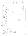
- the FIG. 3 shows the structure and operation of the controller 80 in detail. It comprises a mass flow computer 104, which is supplied with signals from the rangefinder 90 and the speed sensor 102.
- the mass flow calculator 104 determines an expected mass flow rate ⁇ m>', ie the mass of the crop conveyed per unit time from the feederhouse 18 into the combine harvester 10.
- angle brackets ⁇ > indicate an expected, estimated or calculated value, and the hyphen indicates a time derivative.
- This expected mass flow rate is supplied to a first comparator 106, which compares it to a measured mass flow rate from a mass flow rate determiner 116, which will be described below.
- the difference determined by the comparator 106 is fed to a combine model 108, which uses the difference to evaluate an expected pressure ⁇ p>, which is fed to a second comparator 110.
- This expected pressure ⁇ p> corresponds to a pressure of the hydraulic pressure sensor 86, which will cause the not yet harvested, standing in front of the combine harvester 10 and just examined by the rangefinder 90 Erntegut dealing 96.
- the second comparator 110 compares this expected pressure ⁇ p> with a reference pressure p ref , and the difference is fed to a drive circuit 112, which in turn controls the transmission ratio of the hydrostatic transmission 50.
- a controlled system is formed by the front wheels 14, which move the combine harvester 10 across the field at a velocity v predetermined by the hydrostatic transmission 50, the header 16, which receives the crops 96, and the rotor 37, which threshes the crops and separates and whose mass flow rate dependent drive torque is detected by the hydraulic pressure sensor 86.
- the hydraulic pressure sensor 86 thus detects a pressure p R , which is compared by a third comparator 114 with an expected pressure ⁇ p R >, which is formed by means of a Zeitverzögerers 113 from the output signal ⁇ p> of the combine model 108.
- third comparator 114 is supplied to the mass flow rate determiner 116, which converts the difference between the measured pressure p R , the hydraulic pressure sensor 86 and the expected pressure ⁇ p R > at the output of the time delay 113 into a mass error m '.
- the operation of the controller 80 after all is as follows.
- the evaluation unit 98 of the rangefinder 90 derives continuously on the one hand the height h o of the upper edge of the plant population 96 on the field from the receiver 94 received vertically and horizontally polarized waves (see, for this purpose, the prior art DE 10 2011 017 621 A1 ).
- a sensor 118 (or a sensor not shown for detecting the position of the cylinder for height adjustment of the cutting unit 16) which detects the angle of a sliding on the ground Tastbügels 120, is across the width the height of the crop to be included is evaluated by subtracting the respective cutting height h u from the height h o of the upper edge of the crop 96.
- Other ways of determining the cutting height are also conceivable; so it can be derived from the signals of the rangefinder 90 (see. DE 10 2011 017 621 A1 ), whose signals can also be used for cutting height control.
- the measured values for the cutting height h u and / or the height h o of the upper edge of the crop 96 can be corrected by an inertia sensor (not shown) for detecting the orientation of the harvester 10 in space.
- the height of the crop inventory to be included is integrated over the working width of the header 16 and multiplied by the propulsion rate v to determine the expected volume rate ⁇ V T >'which is integrated over time to calculate the ingested volume ⁇ V T >.
- the time derivative ⁇ D >'of the space filling degree of the dry matter content of the plant stand (which can also be called the volumetric solids content) and the time derivative ⁇ W >' of the space filling degree of the water content of the plant stand (which is also called volumetric water content) is calculated, which is done on the basis of the horizontal and vertical components of the received waves reflected by the plant 96.
- the space filling degree ⁇ is the proportion of plants in the volume filled by the plant stock 96.
- ⁇ D > ⁇ , ⁇ W >'and ⁇ V T > and optionally ⁇ V T >' are continuously detected and fed to the mass flow calculator 104.
- This continuously calculates one mass density ⁇ m> according to the following formula: ⁇ m > ' ⁇ D * ⁇ ⁇ D > ' + ⁇ w * ⁇ ⁇ D > ' * ⁇ V T > ,
- ⁇ D is the density of the dry mass and ⁇ W is the density of the water. Both are known and can be considered constant. All other variables are also known, so that the mass flow calculator 104 is able to calculate the bulk density dependent mass flow rate ⁇ m>'.
- the combine harvester model 108 also receives the size of the threshing gap d and the rotational speed ⁇ R of the rotor 37 and optionally further operating parameters of the harvester 10 on the basis of the mass flow rate from the comparator 106 and on the basis of the further input variables determines the combine model 108 using a mathematical / physical Model continuously the due to the crop to be harvested value ⁇ p> for the pressure in the hydraulic pressure sensor 86.
- the propulsion speed v is continuously adjusted via the comparator 110, the drive circuit 112 and the hydrostatic transmission 50 such that finally reaches a desired target pressure p ref becomes.
- This setpoint pressure p ref can be predefined or be input by the operator, in particular after calibration with a loss test shell.
- the comparator 114 compares the actual pressure p R in the hydraulic cylinder 66 detected with the hydraulic pressure sensor 86 continuously with an expected pressure ⁇ p R >, which, due to the running time of the crop between the detection by the rangefinder 90 and the interaction with the Rotor 37 is cached by the time delay 113 and delayed by this delay is supplied to the comparator 114. Any differences are continuously converted by the mass flow rate determiner 116 into mass flow rates m 'that are continuously subtracted by the mass flow rate ⁇ m>' by the first comparator 106.
- the mass flow rate determiner 116 serves as feedback of the actual pressure values to the combine model 108 and may be referred to as Return factor or matrix executed.
- the mode of operation of the controller 80 can be summarized in such a way that the rangefinder 90 detects forward-looking changes in the mass flow rate.
- the combine model 108 calculates an expected mass flow rate value (here, the pressure in the hydraulic pressure sensor 86) that is used (in cooperation with the second comparator 110, the drive circuit 112, and the swash plates of the hydrostatic transmission 50) by the propulsion speed v of the combine 10 to maintain a desired value of the mass flow rate, using data from the rangefinder 90.
- An under review control observer feedback circuit to detect the actual mass flow rate detects a quantity dependent on the actual mass flow rate (also the pressure p R in the hydraulic pressure sensor 86) and a possible deviation between the expected and measured mass flow rate (or the respective mass flow rate) ng stationary pressure values ⁇ p R > and p R ) and returns them to the combine model 108 on the input side as a correction variable to adjust the state of the combine model 108 accordingly.
- the mass flow computer 104 and the combine model 108 implement software-implemented, physical or mathematical multi-size models and can be linear or non-linear, dynamic or static, time-varying or time-invariant, machine-based or neural networks or characteristic or map-based realized.
- the present invention is suitable not only for standing plants 84, as described above, but also for in a swath or flat plants.
- Further input variables of the combine model 108 for determining the expected pressure ⁇ p> can also be harvested crop properties, such as moisture of the straw and / or the ears or mechanical properties of the crop or the fraction of broken grain in the grain tank 28 or by means of a loss sensor (not shown) Outlet of the rotor 37 and / or the cleaning system 26 and / or the mass flow rate and / or grain fraction serve in a return conveyor.
- harvested crop properties such as moisture of the straw and / or the ears or mechanical properties of the crop or the fraction of broken grain in the grain tank 28 or by means of a loss sensor (not shown)
- Outlet of the rotor 37 and / or the cleaning system 26 and / or the mass flow rate and / or grain fraction serve in a return conveyor.
Landscapes
- Life Sciences & Earth Sciences (AREA)
- Environmental Sciences (AREA)
- Combines (AREA)
Applications Claiming Priority (1)
| Application Number | Priority Date | Filing Date | Title |
|---|---|---|---|
| DE102013209197.4A DE102013209197A1 (de) | 2013-05-17 | 2013-05-17 | Erntemaschine mit vorausschauender Vortriebsgeschwindigkeitsregelung |
Publications (2)
| Publication Number | Publication Date |
|---|---|
| EP2803256A1 true EP2803256A1 (fr) | 2014-11-19 |
| EP2803256B1 EP2803256B1 (fr) | 2017-01-25 |
Family
ID=50513150
Family Applications (1)
| Application Number | Title | Priority Date | Filing Date |
|---|---|---|---|
| EP14165608.2A Active EP2803256B1 (fr) | 2013-05-17 | 2014-04-23 | Moissonneuse dotée d'un réglage de la vitesse de propulsion anticipé |
Country Status (3)
| Country | Link |
|---|---|
| US (1) | US9485905B2 (fr) |
| EP (1) | EP2803256B1 (fr) |
| DE (1) | DE102013209197A1 (fr) |
Cited By (7)
| Publication number | Priority date | Publication date | Assignee | Title |
|---|---|---|---|---|
| EP2921042A1 (fr) * | 2014-03-20 | 2015-09-23 | Deere & Company | Moissonneuse dotée d'un réglage de la vitesse de propulsion anticipé |
| WO2017060168A1 (fr) * | 2015-10-05 | 2017-04-13 | Bayer Cropscience Ag | Procédé de fonctionnement d'une récolteuse à l'aide d'un modèle de croissance végétale |
| EP3298872A1 (fr) * | 2016-09-27 | 2018-03-28 | Deere & Company | Système d'entraînement d'un véhicule de travail |
| EP3598886A1 (fr) * | 2018-07-24 | 2020-01-29 | CLAAS Selbstfahrende Erntemaschinen GmbH | Engin d'abattage-façonnage automoteur |
| US20240251713A1 (en) * | 2023-01-31 | 2024-08-01 | Claas Selbstfahrende Erntemaschinen Gmbh | Self-propelled agricultural harvester |
| EP3556547B1 (fr) * | 2018-04-17 | 2025-10-29 | Usines Claas France S.A.S | Presse à balles agricole ainsi que son procédé de fonctionnement |
| EP4649811A1 (fr) * | 2024-05-13 | 2025-11-19 | CLAAS Selbstfahrende Erntemaschinen GmbH | Maïs-ges pour une truie de champ |
Families Citing this family (97)
| Publication number | Priority date | Publication date | Assignee | Title |
|---|---|---|---|---|
| US10321624B2 (en) | 2011-03-11 | 2019-06-18 | Intelligent Agriculture Solutions LLC | Air seeder manifold system |
| US9631964B2 (en) | 2011-03-11 | 2017-04-25 | Intelligent Agricultural Solutions, Llc | Acoustic material flow sensor |
| US9629308B2 (en) | 2011-03-11 | 2017-04-25 | Intelligent Agricultural Solutions, Llc | Harvesting machine capable of automatic adjustment |
| US10318138B2 (en) | 2011-03-11 | 2019-06-11 | Intelligent Agricultural Solutions Llc | Harvesting machine capable of automatic adjustment |
| DE102014105820A1 (de) * | 2014-04-25 | 2015-10-29 | Usines Claas France S.A.S. | Kombination aus einem Zugfahrzeug und einer davon gezogenen Erntemaschine |
| US10034423B2 (en) * | 2014-07-29 | 2018-07-31 | Deere & Company | Biomass sensing |
| AU2015314684B2 (en) | 2014-09-12 | 2020-09-03 | Precision Planting, Llc | Non-image-based grain quality sensor |
| US10085379B2 (en) | 2014-09-12 | 2018-10-02 | Appareo Systems, Llc | Grain quality sensor |
| US9848537B2 (en) * | 2015-04-15 | 2017-12-26 | Agco International Gmbh | Drive system for combine harvester processor |
| EP3114919B1 (fr) * | 2015-07-08 | 2020-10-28 | Zürn Harvesting GmbH & Co. KG | Systeme de tête de coupe |
| DE102015122269A1 (de) * | 2015-12-18 | 2017-06-22 | Claas Selbstfahrende Erntemaschinen Gmbh | Verfahren für den Betrieb eines Mähdreschers |
| JP6594830B2 (ja) * | 2016-07-19 | 2019-10-23 | ヤンマー株式会社 | コンバイン |
| DE102016223133A1 (de) * | 2016-11-23 | 2018-05-24 | Deere & Company | Geschwindigkeitskontrolle einer Erntemaschine |
| EP3342274B1 (fr) * | 2016-12-30 | 2019-08-14 | AGCO Corporation | Profil de bande de capteur basé sur une fusion |
| DE102017200336A1 (de) * | 2017-01-11 | 2018-07-12 | Deere & Company | Modellbasierte prädiktive Geschwindigkeitskontrolle einer Erntemaschine |
| DE102017207347A1 (de) | 2017-05-02 | 2018-11-08 | Deere & Company | Verfahren und Anordnung zur Kontrolle der Geschwindigkeit einer Ballenpresse |
| EP3646705B1 (fr) * | 2017-06-26 | 2023-10-18 | Kubota Corporation | Machine à moissonner |
| US10412888B2 (en) | 2017-08-21 | 2019-09-17 | Cnh Industrial America Llc | System and method for controlling elevator speeds for an agricultural harvester during operation within a storage harvesting mode |
| US11140807B2 (en) | 2017-09-07 | 2021-10-12 | Deere & Company | System for optimizing agricultural machine settings |
| US11744180B2 (en) | 2018-01-29 | 2023-09-05 | Deere & Company | Harvester crop mapping |
| US10827676B2 (en) | 2018-01-29 | 2020-11-10 | Deere & Company | Monitor and control system for a harvester |
| US10806079B2 (en) | 2018-02-26 | 2020-10-20 | Deere & Company | Automatic product harvesting method and control system |
| BR102018075214B1 (pt) * | 2018-03-06 | 2023-09-26 | Cnh Industrial Brasil Ltda | Sistema para detectar níveis de cultura em uma colheitadeira agrícola e método para operar uma colheitadeira agrícola |
| DE102018204301B4 (de) * | 2018-03-21 | 2020-06-18 | Robert Bosch Gmbh | Verfahren zum Ermitteln einer Bestandhöhe von Feldpflanzen |
| US11589509B2 (en) | 2018-10-26 | 2023-02-28 | Deere & Company | Predictive machine characteristic map generation and control system |
| US11957072B2 (en) | 2020-02-06 | 2024-04-16 | Deere & Company | Pre-emergence weed detection and mitigation system |
| US11079725B2 (en) | 2019-04-10 | 2021-08-03 | Deere & Company | Machine control using real-time model |
| US11240961B2 (en) | 2018-10-26 | 2022-02-08 | Deere & Company | Controlling a harvesting machine based on a geo-spatial representation indicating where the harvesting machine is likely to reach capacity |
| US11653588B2 (en) | 2018-10-26 | 2023-05-23 | Deere & Company | Yield map generation and control system |
| US11641800B2 (en) | 2020-02-06 | 2023-05-09 | Deere & Company | Agricultural harvesting machine with pre-emergence weed detection and mitigation system |
| US11467605B2 (en) | 2019-04-10 | 2022-10-11 | Deere & Company | Zonal machine control |
| US11672203B2 (en) | 2018-10-26 | 2023-06-13 | Deere & Company | Predictive map generation and control |
| US12069978B2 (en) | 2018-10-26 | 2024-08-27 | Deere & Company | Predictive environmental characteristic map generation and control system |
| US11178818B2 (en) | 2018-10-26 | 2021-11-23 | Deere & Company | Harvesting machine control system with fill level processing based on yield data |
| US10980166B2 (en) * | 2018-11-20 | 2021-04-20 | Cnh Industrial America Llc | System and method for pre-emptively adjusting machine parameters based on predicted field conditions |
| US11234366B2 (en) | 2019-04-10 | 2022-02-01 | Deere & Company | Image selection for machine control |
| US11778945B2 (en) | 2019-04-10 | 2023-10-10 | Deere & Company | Machine control using real-time model |
| DE102019111089A1 (de) * | 2019-04-30 | 2020-11-05 | Claas Selbstfahrende Erntemaschinen Gmbh | Verfahren zur Ernte eines auf einem Feld angeordneten Bestandes zu erntender Pflanzen wie Mähdrescher |
| US11793111B2 (en) * | 2019-11-27 | 2023-10-24 | Cnh Industrial America Llc | Harvesting head reel-mounted laser measurement |
| EP3854190B1 (fr) * | 2020-01-23 | 2023-11-08 | CNH Industrial Belgium N.V. | Systèmes et procédés pour surveiller des conditions de travail du sol |
| US11533844B2 (en) | 2020-01-31 | 2022-12-27 | Cnh Industrial America Llc | Load based ground speed control method |
| US12329148B2 (en) | 2020-02-06 | 2025-06-17 | Deere & Company | Predictive weed map and material application machine control |
| US12225846B2 (en) | 2020-02-06 | 2025-02-18 | Deere & Company | Machine control using a predictive map |
| US12035648B2 (en) | 2020-02-06 | 2024-07-16 | Deere & Company | Predictive weed map generation and control system |
| US11477940B2 (en) | 2020-03-26 | 2022-10-25 | Deere & Company | Mobile work machine control based on zone parameter modification |
| US20220110258A1 (en) | 2020-10-09 | 2022-04-14 | Deere & Company | Map generation and control system |
| US11927459B2 (en) | 2020-10-09 | 2024-03-12 | Deere & Company | Machine control using a predictive map |
| US11474523B2 (en) | 2020-10-09 | 2022-10-18 | Deere & Company | Machine control using a predictive speed map |
| US12013245B2 (en) | 2020-10-09 | 2024-06-18 | Deere & Company | Predictive map generation and control system |
| US11635765B2 (en) | 2020-10-09 | 2023-04-25 | Deere & Company | Crop state map generation and control system |
| US12386354B2 (en) | 2020-10-09 | 2025-08-12 | Deere & Company | Predictive power map generation and control system |
| US11825768B2 (en) | 2020-10-09 | 2023-11-28 | Deere & Company | Machine control using a predictive map |
| US11675354B2 (en) | 2020-10-09 | 2023-06-13 | Deere & Company | Machine control using a predictive map |
| US11864483B2 (en) | 2020-10-09 | 2024-01-09 | Deere & Company | Predictive map generation and control system |
| US12419220B2 (en) | 2020-10-09 | 2025-09-23 | Deere & Company | Predictive map generation and control system |
| US11711995B2 (en) | 2020-10-09 | 2023-08-01 | Deere & Company | Machine control using a predictive map |
| US11983009B2 (en) | 2020-10-09 | 2024-05-14 | Deere & Company | Map generation and control system |
| US11650587B2 (en) | 2020-10-09 | 2023-05-16 | Deere & Company | Predictive power map generation and control system |
| US11946747B2 (en) | 2020-10-09 | 2024-04-02 | Deere & Company | Crop constituent map generation and control system |
| US12178158B2 (en) | 2020-10-09 | 2024-12-31 | Deere & Company | Predictive map generation and control system for an agricultural work machine |
| US12069986B2 (en) | 2020-10-09 | 2024-08-27 | Deere & Company | Map generation and control system |
| US20220110238A1 (en) | 2020-10-09 | 2022-04-14 | Deere & Company | Machine control using a predictive map |
| US11727680B2 (en) | 2020-10-09 | 2023-08-15 | Deere & Company | Predictive map generation based on seeding characteristics and control |
| US11871697B2 (en) | 2020-10-09 | 2024-01-16 | Deere & Company | Crop moisture map generation and control system |
| US11849671B2 (en) | 2020-10-09 | 2023-12-26 | Deere & Company | Crop state map generation and control system |
| US12422847B2 (en) | 2020-10-09 | 2025-09-23 | Deere & Company | Predictive agricultural model and map generation |
| US12550802B2 (en) | 2020-10-08 | 2026-02-17 | Deere & Company | Predictive machine characteristic map generation and control system |
| US11845449B2 (en) | 2020-10-09 | 2023-12-19 | Deere & Company | Map generation and control system |
| US11844311B2 (en) | 2020-10-09 | 2023-12-19 | Deere & Company | Machine control using a predictive map |
| US11889788B2 (en) | 2020-10-09 | 2024-02-06 | Deere & Company | Predictive biomass map generation and control |
| US11874669B2 (en) | 2020-10-09 | 2024-01-16 | Deere & Company | Map generation and control system |
| US11592822B2 (en) | 2020-10-09 | 2023-02-28 | Deere & Company | Machine control using a predictive map |
| US11895948B2 (en) | 2020-10-09 | 2024-02-13 | Deere & Company | Predictive map generation and control based on soil properties |
| US11849672B2 (en) | 2020-10-09 | 2023-12-26 | Deere & Company | Machine control using a predictive map |
| US12250905B2 (en) | 2020-10-09 | 2025-03-18 | Deere & Company | Machine control using a predictive map |
| US11889787B2 (en) | 2020-10-09 | 2024-02-06 | Deere & Company | Predictive speed map generation and control system |
| US12127500B2 (en) | 2021-01-27 | 2024-10-29 | Deere & Company | Machine control using a map with regime zones |
| DE102021113838A1 (de) | 2021-05-28 | 2022-12-01 | Deere & Company | Feldhäcksler mit vorausschauender Ansteuerung des Bearbeitungsgrads eines Körnerprozessors |
| US20220410704A1 (en) * | 2021-06-28 | 2022-12-29 | Deere & Company | Communication of fill level to receiving vehicle(s) |
| US12229886B2 (en) | 2021-10-01 | 2025-02-18 | Deere & Company | Historical crop state model, predictive crop state map generation and control system |
| US12310286B2 (en) | 2021-12-14 | 2025-05-27 | Deere & Company | Crop constituent sensing |
| US12302791B2 (en) | 2021-12-20 | 2025-05-20 | Deere & Company | Crop constituents, predictive mapping, and agricultural harvester control |
| US12245549B2 (en) | 2022-01-11 | 2025-03-11 | Deere & Company | Predictive response map generation and control system |
| US12520759B2 (en) | 2022-01-26 | 2026-01-13 | Deere & Company | Systems and methods for predicting material dynamics |
| US12082531B2 (en) | 2022-01-26 | 2024-09-10 | Deere & Company | Systems and methods for predicting material dynamics |
| US12396392B2 (en) * | 2022-04-01 | 2025-08-26 | Deere & Company | Crop feed rate control system for a harvester vehicle |
| US12295288B2 (en) | 2022-04-05 | 2025-05-13 | Deere &Company | Predictive machine setting map generation and control system |
| US12582035B2 (en) | 2022-04-08 | 2026-03-24 | Deere & Company | Systems and methods for predictive power requirements and control |
| US12058951B2 (en) | 2022-04-08 | 2024-08-13 | Deere & Company | Predictive nutrient map and control |
| US12358493B2 (en) | 2022-04-08 | 2025-07-15 | Deere & Company | Systems and methods for predictive power requirements and control |
| US12298767B2 (en) | 2022-04-08 | 2025-05-13 | Deere & Company | Predictive material consumption map and control |
| US12284934B2 (en) | 2022-04-08 | 2025-04-29 | Deere & Company | Systems and methods for predictive tractive characteristics and control |
| US20240138296A1 (en) * | 2022-11-01 | 2024-05-02 | Cnh Industrial America Llc | System and method for determining crop population within a field during a harvesting operation being performed by an agricultural harvester |
| CN116746361B (zh) * | 2023-06-30 | 2026-04-10 | 江苏大学 | 一种水稻收获属性检测及作业调控系统和方法及收获机 |
| DE102023120264A1 (de) | 2023-07-31 | 2025-02-06 | Claas Selbstfahrende Erntemaschinen Gmbh | Erntemaschine |
| DE102024124312A1 (de) | 2024-05-13 | 2025-11-13 | Claas Selbstfahrende Erntemaschinen Gmbh | Maisgebiss für einen Feldhäcksler |
| CN118414970B (zh) * | 2024-05-27 | 2024-12-20 | 中国农业大学 | 一种联合收获机速度控制方法及控制系统 |
Citations (6)
| Publication number | Priority date | Publication date | Assignee | Title |
|---|---|---|---|---|
| EP1243173A1 (fr) | 2001-03-20 | 2002-09-25 | Deere & Company | Convoyeur élévateur muni d'un capteur de force pour détecter le débit d'une moissonneuse-batteuse |
| DE10130665A1 (de) | 2001-06-28 | 2003-01-23 | Deere & Co | Vorrichtung zur Messung der Menge von auf einem Feld stehenden Pflanzen |
| CA2530090A1 (fr) * | 2005-12-14 | 2007-06-14 | Deere & Company | Machine de recolte automotrice |
| EP2060165A1 (fr) * | 2007-11-16 | 2009-05-20 | CLAAS Selbstfahrende Erntemaschinen GmbH | Moissonneuse agricole automatique |
| DE102011017621A1 (de) | 2011-04-27 | 2012-10-31 | Deere & Company | Anordnung und Verfahren zur Erfassung der Menge von Pflanzen auf einem Feld |
| DE102011085380A1 (de) | 2011-10-28 | 2013-05-02 | Deere & Company | Anordnung und Verfahren zur vorausschauenden Untersuchung von mit einer Erntemaschine aufzunehmenden Pflanzen |
Family Cites Families (4)
| Publication number | Priority date | Publication date | Assignee | Title |
|---|---|---|---|---|
| US5995895A (en) * | 1997-07-15 | 1999-11-30 | Case Corporation | Control of vehicular systems in response to anticipated conditions predicted using predetermined geo-referenced maps |
| US6119442A (en) * | 1999-05-14 | 2000-09-19 | Case Corporation | Combine setting autoadjust with machine vision |
| US8073599B2 (en) * | 2004-07-09 | 2011-12-06 | Deere & Company | Conveying duct monitor system for controlling harvester speed |
| DE102004059543A1 (de) * | 2004-12-09 | 2006-06-29 | Claas Selbstfahrende Erntemaschinen Gmbh | Landwirtschaftliche Arbeitsmaschine |
-
2013
- 2013-05-17 DE DE102013209197.4A patent/DE102013209197A1/de not_active Withdrawn
-
2014
- 2014-03-20 US US14/220,575 patent/US9485905B2/en active Active
- 2014-04-23 EP EP14165608.2A patent/EP2803256B1/fr active Active
Patent Citations (6)
| Publication number | Priority date | Publication date | Assignee | Title |
|---|---|---|---|---|
| EP1243173A1 (fr) | 2001-03-20 | 2002-09-25 | Deere & Company | Convoyeur élévateur muni d'un capteur de force pour détecter le débit d'une moissonneuse-batteuse |
| DE10130665A1 (de) | 2001-06-28 | 2003-01-23 | Deere & Co | Vorrichtung zur Messung der Menge von auf einem Feld stehenden Pflanzen |
| CA2530090A1 (fr) * | 2005-12-14 | 2007-06-14 | Deere & Company | Machine de recolte automotrice |
| EP2060165A1 (fr) * | 2007-11-16 | 2009-05-20 | CLAAS Selbstfahrende Erntemaschinen GmbH | Moissonneuse agricole automatique |
| DE102011017621A1 (de) | 2011-04-27 | 2012-10-31 | Deere & Company | Anordnung und Verfahren zur Erfassung der Menge von Pflanzen auf einem Feld |
| DE102011085380A1 (de) | 2011-10-28 | 2013-05-02 | Deere & Company | Anordnung und Verfahren zur vorausschauenden Untersuchung von mit einer Erntemaschine aufzunehmenden Pflanzen |
Cited By (15)
| Publication number | Priority date | Publication date | Assignee | Title |
|---|---|---|---|---|
| EP2921042A1 (fr) * | 2014-03-20 | 2015-09-23 | Deere & Company | Moissonneuse dotée d'un réglage de la vitesse de propulsion anticipé |
| US9521805B2 (en) | 2014-03-20 | 2016-12-20 | Deere & Company | Harvester with predictive driving speed specification |
| US10856463B2 (en) | 2015-10-05 | 2020-12-08 | Basf Agro Trademarks Gmbh | Method for operating a harvesting machine with the aid of a plant growth model |
| CN108135132A (zh) * | 2015-10-05 | 2018-06-08 | 拜耳农作物科学股份公司 | 用于在植物生长模型的帮助下操作收割机器的方法 |
| EP3358932B1 (fr) | 2015-10-05 | 2020-04-15 | BASF Agro Trademarks GmbH | Procede de fonctionnement d'une moissonneuse a l'aide d'un modele de croissance de plante |
| EP3707988A1 (fr) | 2015-10-05 | 2020-09-16 | BASF Agro Trademarks GmbH | Procédé de fonctionnement d'une moissonneuse a l'aide d'un modele de croissance de plante |
| WO2017060168A1 (fr) * | 2015-10-05 | 2017-04-13 | Bayer Cropscience Ag | Procédé de fonctionnement d'une récolteuse à l'aide d'un modèle de croissance végétale |
| CN115708443A (zh) * | 2015-10-05 | 2023-02-24 | 拜耳农作物科学股份公司 | 用于在植物生长模型的帮助下操作收割机器的方法 |
| US11812683B2 (en) | 2015-10-05 | 2023-11-14 | Basf Agro Trademarks Gmbh | Method for operating a harvesting machine with the aid of a plant growth model |
| EP3298872A1 (fr) * | 2016-09-27 | 2018-03-28 | Deere & Company | Système d'entraînement d'un véhicule de travail |
| US10827675B2 (en) | 2016-09-27 | 2020-11-10 | Deere & Company | Drive system of a utility vehicle |
| EP3556547B1 (fr) * | 2018-04-17 | 2025-10-29 | Usines Claas France S.A.S | Presse à balles agricole ainsi que son procédé de fonctionnement |
| EP3598886A1 (fr) * | 2018-07-24 | 2020-01-29 | CLAAS Selbstfahrende Erntemaschinen GmbH | Engin d'abattage-façonnage automoteur |
| US20240251713A1 (en) * | 2023-01-31 | 2024-08-01 | Claas Selbstfahrende Erntemaschinen Gmbh | Self-propelled agricultural harvester |
| EP4649811A1 (fr) * | 2024-05-13 | 2025-11-19 | CLAAS Selbstfahrende Erntemaschinen GmbH | Maïs-ges pour une truie de champ |
Also Published As
| Publication number | Publication date |
|---|---|
| US9485905B2 (en) | 2016-11-08 |
| DE102013209197A1 (de) | 2014-11-20 |
| US20140338298A1 (en) | 2014-11-20 |
| EP2803256B1 (fr) | 2017-01-25 |
Similar Documents
| Publication | Publication Date | Title |
|---|---|---|
| EP2803256B1 (fr) | Moissonneuse dotée d'un réglage de la vitesse de propulsion anticipé | |
| EP2517549B1 (fr) | Agencement et procédé de détection de la quantité de plantes sur un champ | |
| EP2586286B1 (fr) | Agencement et procédé destinés à l'examen prévisionnel de plantes récoltées avec une moissonneuse | |
| EP2921042B1 (fr) | Moissonneuse dotée d'un réglage de la vitesse de propulsion anticipé | |
| DE102008017671B4 (de) | Messanordnung zur Massendurchsatzerfassung mit Massen- und Volumenmessung und darauf basierender Massendichtenbestimmung sowie Massendurchsatzangabe bei kleinen Durchsätzen anhand der zuletzt erfassten Massendichte | |
| EP0760202B1 (fr) | Dispositif pour remplir des récipients de chargements | |
| EP3300580B2 (fr) | Moissonneuse-batteuse pourvue de barre de coupe et dispositif de commande d'une barre de coupe | |
| DE102008043716B4 (de) | Vorrichtung und Verfahren zur Erfassung der Bestandsdichte von Pflanzen auf einem Feld | |
| EP1408732B1 (fr) | Dispositif de distribution con u pour des produits haches issus d'une recolteuse | |
| EP1266558B1 (fr) | Convoyeur élévateur muni d'un capteur de force pour détecter le débit d' une moissonneuse-bateuse | |
| EP1271139B1 (fr) | Dispositif de mesure de la quantité de plantes en hauteur dans un champ | |
| EP2829171B1 (fr) | Moissonneuse automotrice et véhicule associé | |
| EP1297734B1 (fr) | Machine de récolte avec une vitesse d'avance qui est dépendante de l'inclinaison | |
| DE102014208068A1 (de) | Erntemaschine mit sensorbasierter Einstellung eines Arbeitsparameters | |
| EP2939518B1 (fr) | Système de vérification prenant en compte la dynamique de véhicule destiné au réglage de position d'un appareil pour un véhicule de travail agricole | |
| EP2873315B1 (fr) | Machine de récolte | |
| DE19903471C1 (de) | Erntemaschine mit Durchsatzmeßvorrichtung | |
| EP2918159A1 (fr) | Agencement et procédé de reconnaissance et documentation de qualité de paille | |
| EP3766329A1 (fr) | Engin d'abattage-façonnage agricole | |
| EP1281310A1 (fr) | Machine de récolte avec contrôle de la vitesse | |
| EP3072379A1 (fr) | Amortissement du tangage d'un vehicule de travail par modification de la vitesse | |
| EP2761984A1 (fr) | Capteur d'oscillations | |
| EP1243173A1 (fr) | Convoyeur élévateur muni d'un capteur de force pour détecter le débit d'une moissonneuse-batteuse | |
| EP2845461A1 (fr) | Agencement de mesure de perte dans une moissonneuse-batteuse | |
| DE102018104288B4 (de) | Selbstfahrender Feldhäcksler |
Legal Events
| Date | Code | Title | Description |
|---|---|---|---|
| PUAI | Public reference made under article 153(3) epc to a published international application that has entered the european phase |
Free format text: ORIGINAL CODE: 0009012 |
|
| 17P | Request for examination filed |
Effective date: 20140423 |
|
| AK | Designated contracting states |
Kind code of ref document: A1 Designated state(s): AL AT BE BG CH CY CZ DE DK EE ES FI FR GB GR HR HU IE IS IT LI LT LU LV MC MK MT NL NO PL PT RO RS SE SI SK SM TR |
|
| AX | Request for extension of the european patent |
Extension state: BA ME |
|
| R17P | Request for examination filed (corrected) |
Effective date: 20150519 |
|
| RBV | Designated contracting states (corrected) |
Designated state(s): AL AT BE BG CH CY CZ DE DK EE ES FI FR GB GR HR HU IE IS IT LI LT LU LV MC MK MT NL NO PL PT RO RS SE SI SK SM TR |
|
| RIC1 | Information provided on ipc code assigned before grant |
Ipc: A01D 41/127 20060101AFI20160810BHEP |
|
| GRAP | Despatch of communication of intention to grant a patent |
Free format text: ORIGINAL CODE: EPIDOSNIGR1 |
|
| INTG | Intention to grant announced |
Effective date: 20160927 |
|
| GRAS | Grant fee paid |
Free format text: ORIGINAL CODE: EPIDOSNIGR3 |
|
| GRAA | (expected) grant |
Free format text: ORIGINAL CODE: 0009210 |
|
| AK | Designated contracting states |
Kind code of ref document: B1 Designated state(s): AL AT BE BG CH CY CZ DE DK EE ES FI FR GB GR HR HU IE IS IT LI LT LU LV MC MK MT NL NO PL PT RO RS SE SI SK SM TR |
|
| REG | Reference to a national code |
Ref country code: GB Ref legal event code: FG4D Free format text: NOT ENGLISH |
|
| REG | Reference to a national code |
Ref country code: CH Ref legal event code: EP |
|
| REG | Reference to a national code |
Ref country code: AT Ref legal event code: REF Ref document number: 863560 Country of ref document: AT Kind code of ref document: T Effective date: 20170215 |
|
| REG | Reference to a national code |
Ref country code: IE Ref legal event code: FG4D Free format text: LANGUAGE OF EP DOCUMENT: GERMAN |
|
| REG | Reference to a national code |
Ref country code: DE Ref legal event code: R096 Ref document number: 502014002525 Country of ref document: DE |
|
| REG | Reference to a national code |
Ref country code: LT Ref legal event code: MG4D |
|
| REG | Reference to a national code |
Ref country code: NL Ref legal event code: MP Effective date: 20170125 |
|
| PG25 | Lapsed in a contracting state [announced via postgrant information from national office to epo] |
Ref country code: NL Free format text: LAPSE BECAUSE OF FAILURE TO SUBMIT A TRANSLATION OF THE DESCRIPTION OR TO PAY THE FEE WITHIN THE PRESCRIBED TIME-LIMIT Effective date: 20170125 |
|
| PG25 | Lapsed in a contracting state [announced via postgrant information from national office to epo] |
Ref country code: IS Free format text: LAPSE BECAUSE OF FAILURE TO SUBMIT A TRANSLATION OF THE DESCRIPTION OR TO PAY THE FEE WITHIN THE PRESCRIBED TIME-LIMIT Effective date: 20170525 Ref country code: FI Free format text: LAPSE BECAUSE OF FAILURE TO SUBMIT A TRANSLATION OF THE DESCRIPTION OR TO PAY THE FEE WITHIN THE PRESCRIBED TIME-LIMIT Effective date: 20170125 Ref country code: HR Free format text: LAPSE BECAUSE OF FAILURE TO SUBMIT A TRANSLATION OF THE DESCRIPTION OR TO PAY THE FEE WITHIN THE PRESCRIBED TIME-LIMIT Effective date: 20170125 Ref country code: NO Free format text: LAPSE BECAUSE OF FAILURE TO SUBMIT A TRANSLATION OF THE DESCRIPTION OR TO PAY THE FEE WITHIN THE PRESCRIBED TIME-LIMIT Effective date: 20170425 Ref country code: LT Free format text: LAPSE BECAUSE OF FAILURE TO SUBMIT A TRANSLATION OF THE DESCRIPTION OR TO PAY THE FEE WITHIN THE PRESCRIBED TIME-LIMIT Effective date: 20170125 Ref country code: GR Free format text: LAPSE BECAUSE OF FAILURE TO SUBMIT A TRANSLATION OF THE DESCRIPTION OR TO PAY THE FEE WITHIN THE PRESCRIBED TIME-LIMIT Effective date: 20170426 |
|
| PG25 | Lapsed in a contracting state [announced via postgrant information from national office to epo] |
Ref country code: PT Free format text: LAPSE BECAUSE OF FAILURE TO SUBMIT A TRANSLATION OF THE DESCRIPTION OR TO PAY THE FEE WITHIN THE PRESCRIBED TIME-LIMIT Effective date: 20170525 Ref country code: PL Free format text: LAPSE BECAUSE OF FAILURE TO SUBMIT A TRANSLATION OF THE DESCRIPTION OR TO PAY THE FEE WITHIN THE PRESCRIBED TIME-LIMIT Effective date: 20170125 Ref country code: BG Free format text: LAPSE BECAUSE OF FAILURE TO SUBMIT A TRANSLATION OF THE DESCRIPTION OR TO PAY THE FEE WITHIN THE PRESCRIBED TIME-LIMIT Effective date: 20170425 Ref country code: ES Free format text: LAPSE BECAUSE OF FAILURE TO SUBMIT A TRANSLATION OF THE DESCRIPTION OR TO PAY THE FEE WITHIN THE PRESCRIBED TIME-LIMIT Effective date: 20170125 Ref country code: RS Free format text: LAPSE BECAUSE OF FAILURE TO SUBMIT A TRANSLATION OF THE DESCRIPTION OR TO PAY THE FEE WITHIN THE PRESCRIBED TIME-LIMIT Effective date: 20170125 Ref country code: SE Free format text: LAPSE BECAUSE OF FAILURE TO SUBMIT A TRANSLATION OF THE DESCRIPTION OR TO PAY THE FEE WITHIN THE PRESCRIBED TIME-LIMIT Effective date: 20170125 Ref country code: LV Free format text: LAPSE BECAUSE OF FAILURE TO SUBMIT A TRANSLATION OF THE DESCRIPTION OR TO PAY THE FEE WITHIN THE PRESCRIBED TIME-LIMIT Effective date: 20170125 |
|
| REG | Reference to a national code |
Ref country code: DE Ref legal event code: R097 Ref document number: 502014002525 Country of ref document: DE |
|
| PG25 | Lapsed in a contracting state [announced via postgrant information from national office to epo] |
Ref country code: EE Free format text: LAPSE BECAUSE OF FAILURE TO SUBMIT A TRANSLATION OF THE DESCRIPTION OR TO PAY THE FEE WITHIN THE PRESCRIBED TIME-LIMIT Effective date: 20170125 Ref country code: CZ Free format text: LAPSE BECAUSE OF FAILURE TO SUBMIT A TRANSLATION OF THE DESCRIPTION OR TO PAY THE FEE WITHIN THE PRESCRIBED TIME-LIMIT Effective date: 20170125 Ref country code: RO Free format text: LAPSE BECAUSE OF FAILURE TO SUBMIT A TRANSLATION OF THE DESCRIPTION OR TO PAY THE FEE WITHIN THE PRESCRIBED TIME-LIMIT Effective date: 20170125 Ref country code: SK Free format text: LAPSE BECAUSE OF FAILURE TO SUBMIT A TRANSLATION OF THE DESCRIPTION OR TO PAY THE FEE WITHIN THE PRESCRIBED TIME-LIMIT Effective date: 20170125 |
|
| PG25 | Lapsed in a contracting state [announced via postgrant information from national office to epo] |
Ref country code: SM Free format text: LAPSE BECAUSE OF FAILURE TO SUBMIT A TRANSLATION OF THE DESCRIPTION OR TO PAY THE FEE WITHIN THE PRESCRIBED TIME-LIMIT Effective date: 20170125 Ref country code: DK Free format text: LAPSE BECAUSE OF FAILURE TO SUBMIT A TRANSLATION OF THE DESCRIPTION OR TO PAY THE FEE WITHIN THE PRESCRIBED TIME-LIMIT Effective date: 20170125 |
|
| REG | Reference to a national code |
Ref country code: CH Ref legal event code: PL |
|
| PLBE | No opposition filed within time limit |
Free format text: ORIGINAL CODE: 0009261 |
|
| STAA | Information on the status of an ep patent application or granted ep patent |
Free format text: STATUS: NO OPPOSITION FILED WITHIN TIME LIMIT |
|
| 26N | No opposition filed |
Effective date: 20171026 |
|
| REG | Reference to a national code |
Ref country code: IE Ref legal event code: MM4A |
|
| REG | Reference to a national code |
Ref country code: FR Ref legal event code: ST Effective date: 20171229 |
|
| PG25 | Lapsed in a contracting state [announced via postgrant information from national office to epo] |
Ref country code: FR Free format text: LAPSE BECAUSE OF NON-PAYMENT OF DUE FEES Effective date: 20170502 Ref country code: MC Free format text: LAPSE BECAUSE OF FAILURE TO SUBMIT A TRANSLATION OF THE DESCRIPTION OR TO PAY THE FEE WITHIN THE PRESCRIBED TIME-LIMIT Effective date: 20170125 |
|
| PG25 | Lapsed in a contracting state [announced via postgrant information from national office to epo] |
Ref country code: SI Free format text: LAPSE BECAUSE OF FAILURE TO SUBMIT A TRANSLATION OF THE DESCRIPTION OR TO PAY THE FEE WITHIN THE PRESCRIBED TIME-LIMIT Effective date: 20170125 Ref country code: LU Free format text: LAPSE BECAUSE OF NON-PAYMENT OF DUE FEES Effective date: 20170423 Ref country code: CH Free format text: LAPSE BECAUSE OF NON-PAYMENT OF DUE FEES Effective date: 20170430 Ref country code: LI Free format text: LAPSE BECAUSE OF NON-PAYMENT OF DUE FEES Effective date: 20170430 |
|
| PG25 | Lapsed in a contracting state [announced via postgrant information from national office to epo] |
Ref country code: IE Free format text: LAPSE BECAUSE OF NON-PAYMENT OF DUE FEES Effective date: 20170423 |
|
| PG25 | Lapsed in a contracting state [announced via postgrant information from national office to epo] |
Ref country code: MT Free format text: LAPSE BECAUSE OF FAILURE TO SUBMIT A TRANSLATION OF THE DESCRIPTION OR TO PAY THE FEE WITHIN THE PRESCRIBED TIME-LIMIT Effective date: 20170125 |
|
| GBPC | Gb: european patent ceased through non-payment of renewal fee |
Effective date: 20180423 |
|
| PG25 | Lapsed in a contracting state [announced via postgrant information from national office to epo] |
Ref country code: GB Free format text: LAPSE BECAUSE OF NON-PAYMENT OF DUE FEES Effective date: 20180423 |
|
| PG25 | Lapsed in a contracting state [announced via postgrant information from national office to epo] |
Ref country code: HU Free format text: LAPSE BECAUSE OF FAILURE TO SUBMIT A TRANSLATION OF THE DESCRIPTION OR TO PAY THE FEE WITHIN THE PRESCRIBED TIME-LIMIT; INVALID AB INITIO Effective date: 20140423 |
|
| PG25 | Lapsed in a contracting state [announced via postgrant information from national office to epo] |
Ref country code: CY Free format text: LAPSE BECAUSE OF FAILURE TO SUBMIT A TRANSLATION OF THE DESCRIPTION OR TO PAY THE FEE WITHIN THE PRESCRIBED TIME-LIMIT Effective date: 20170125 |
|
| PG25 | Lapsed in a contracting state [announced via postgrant information from national office to epo] |
Ref country code: MK Free format text: LAPSE BECAUSE OF FAILURE TO SUBMIT A TRANSLATION OF THE DESCRIPTION OR TO PAY THE FEE WITHIN THE PRESCRIBED TIME-LIMIT Effective date: 20170125 |
|
| PG25 | Lapsed in a contracting state [announced via postgrant information from national office to epo] |
Ref country code: TR Free format text: LAPSE BECAUSE OF FAILURE TO SUBMIT A TRANSLATION OF THE DESCRIPTION OR TO PAY THE FEE WITHIN THE PRESCRIBED TIME-LIMIT Effective date: 20170125 |
|
| PG25 | Lapsed in a contracting state [announced via postgrant information from national office to epo] |
Ref country code: AL Free format text: LAPSE BECAUSE OF FAILURE TO SUBMIT A TRANSLATION OF THE DESCRIPTION OR TO PAY THE FEE WITHIN THE PRESCRIBED TIME-LIMIT Effective date: 20170125 |
|
| REG | Reference to a national code |
Ref country code: AT Ref legal event code: MM01 Ref document number: 863560 Country of ref document: AT Kind code of ref document: T Effective date: 20190423 |
|
| PG25 | Lapsed in a contracting state [announced via postgrant information from national office to epo] |
Ref country code: AT Free format text: LAPSE BECAUSE OF NON-PAYMENT OF DUE FEES Effective date: 20190423 |
|
| PGFP | Annual fee paid to national office [announced via postgrant information from national office to epo] |
Ref country code: IT Payment date: 20220421 Year of fee payment: 9 |
|
| PG25 | Lapsed in a contracting state [announced via postgrant information from national office to epo] |
Ref country code: IT Free format text: LAPSE BECAUSE OF NON-PAYMENT OF DUE FEES Effective date: 20230423 |
|
| PGFP | Annual fee paid to national office [announced via postgrant information from national office to epo] |
Ref country code: DE Payment date: 20250319 Year of fee payment: 12 |
|
| PGFP | Annual fee paid to national office [announced via postgrant information from national office to epo] |
Ref country code: BE Payment date: 20250428 Year of fee payment: 12 |