EP2845461A1 - Agencement de mesure de perte dans une moissonneuse-batteuse - Google Patents
Agencement de mesure de perte dans une moissonneuse-batteuse Download PDFInfo
- Publication number
- EP2845461A1 EP2845461A1 EP14172884.0A EP14172884A EP2845461A1 EP 2845461 A1 EP2845461 A1 EP 2845461A1 EP 14172884 A EP14172884 A EP 14172884A EP 2845461 A1 EP2845461 A1 EP 2845461A1
- Authority
- EP
- European Patent Office
- Prior art keywords
- grain
- grain flow
- flow sensor
- conveyor
- combine harvester
- Prior art date
- Legal status (The legal status is an assumption and is not a legal conclusion. Google has not performed a legal analysis and makes no representation as to the accuracy of the status listed.)
- Granted
Links
Images
Classifications
-
- A—HUMAN NECESSITIES
- A01—AGRICULTURE; FORESTRY; ANIMAL HUSBANDRY; HUNTING; TRAPPING; FISHING
- A01D—HARVESTING; MOWING
- A01D41/00—Combines, i.e. harvesters or mowers combined with threshing devices
- A01D41/12—Details of combines
- A01D41/127—Control or measuring arrangements specially adapted for combines
- A01D41/1271—Control or measuring arrangements specially adapted for combines for measuring crop flow
- A01D41/1272—Control or measuring arrangements specially adapted for combines for measuring crop flow for measuring grain flow
- A01D41/1273—Control or measuring arrangements specially adapted for combines for measuring crop flow for measuring grain flow for measuring grain loss
Definitions
- the invention relates to a device for loss measurement in a combine harvester, comprising a grain flow sensor for detecting the intensity of a grain flow separated in a separator of the combine and a control unit for calculating a grain loss value from the signals of the grain flow sensor.
- Agricultural combines are used to harvest grain and other grains.
- On a field standing or lying plants are cut off or picked up by means of a header and transported by means of an inclined conveyor into the interior of the combine. There, the plants are threshed and fed to a separation system. Grain deposited in the threshing or separating process is cleaned in a cleaning system and temporarily deposited in a grain tank for later transfer to a transport vehicle.
- the threshing process usually takes place by means of a tangential threshing drum or in the threshing section of an axial threshing and separating rotor.
- the separation process is usually carried out by means of separating drums and a straw shaker of a tangential Mehrtrommeldrehishisks or downstream of a Tangentialdrehishis arranged separation rotor or in the separation section of an axial threshing and separation rotor.
- the threshed straw is either placed in a swath on the field for later baling and baling, or passed through a straw chopper and finally spread across the width of the header on the field ,
- a disadvantage here is that the measured values are relatively inaccurate because, on the one hand, the number of detectable grains is relatively small given the correct setting and operation of the combine harvester, and on the other hand, the grains are largely embedded in the straw and thus can not be detected by the baffle plate sensor. Man leads Therefore, it is usually first a calibration in which the readings of a loss display device and the actual losses are detected in the field, for example by means of a loss test shell, and then continues at a speed that leads to the loss indicator to an acceptable loss.
- the US 4 951 031 A proposes to solve this problem to equip the threshing and separating device with a number of Körnerstromsensoren that capture at different points along the path of the crop through the threshing and separating device each of the amount of deposited grains.
- a deposition curve is calculated in order to detect situations in which a relatively high proportion of grain is deposited in the rear region of the separating device. In these situations, experience has shown that there are also high losses, because the straw still contains relatively much grain in the rear area of the separating device, which is finally at least partly expelled to the field.
- a similar arrangement can be found in DE 101 62 354 A1 , However, due to their limited dimensions, the grain current sensors also detect only relatively small numbers of grains which are not always representative in order to provide sufficiently accurate loss data.
- the object underlying the invention is seen to provide an arrangement for loss measurement in a combine harvester, which does not have the problems mentioned or to a lesser extent.
- An arrangement for loss measurement in a combine comprises a grain flow sensor for detecting the intensity of a grain flow deposited in a separator of the combine and a control unit for calculating a grain loss value from the signals of the grain flow sensor.
- the grain flow sensor is assigned to a conveying device for grain arranged between the separating device and a cleaning device.
- the conveyor collects the material deposited by the cleaning device (grain) and transports it to the cleaning device.
- the grain flow sensor is arranged in a section of the way of the Material by the conveyor.
- the grain flow sensor thus detects the collected material, which is conveyed by the conveyor from the separator to the cleaning device. In this way it is achieved that the grain flow sensor is exposed to a larger flow of material than in the prior art, in which it detects only the losses at the outlet of the separator or only one directly from the separator to him striking material flow.
- the grain current sensor provides a larger and more reliable signal that allows for the determination and display of a more reliable loss value than heretofore.
- the grain flow sensor may detect the grain flow downstream of the conveyor or within the conveyor. In particular, it can be arranged downstream or inside a conveying floor or a return trough of the separating device.
- the separating device may comprise a straw shaker or a separating rotor.
- control means is connected to a total grain flow sensor for detecting the total grain flow in the combine and determines the grain loss value from the signals of the grain flow sensor and the total grain flow sensor.
- a total grain flow sensor for detecting the total grain flow in the combine and determines the grain loss value from the signals of the grain flow sensor and the total grain flow sensor.
- respective loss curves or tables can be stored in the control unit for different total grain flows, by means of which the control unit can determine the respective loss for a given grain flow detected by the grain flow sensor.
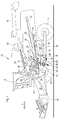
- FIG. 1 shows a self-propelled combine harvester 10 with a frame 12 which is supported by driven front wheels 14 and steerable rear wheels 16 on the ground and is moved away from them.
- the wheels 14 are rotated by means not shown drive means in rotation to the combine 10 z. B. to move over a field to be harvested.
- directional details such as front and rear, refer to the direction of travel V of the combine harvester 10 in harvesting operation.
- a crop gathering device 18 is detachably connected in the form of a cutter to harvest harvested crops in the form of crops or other threshable culottes from the field and feed them up and down by a feeder 20 to a multi-drum threshing unit.
- a threshing cylinder 22 arranged one behind the other - a threshing cylinder 22, a stripping drum 24, a superseding working conveyor drum 26, a Tangentialseparator 28 and a turning drum 30 includes.
- Downstream of the turning drum 30 is a straw shaker 32 with a plurality of laterally juxtaposed Horden thoroughemper.
- the threshing cylinder 22 is surrounded in its lower and rearward area by a concave 34.
- a finger rake 38 is arranged below the conveyor drum 26.
- a front conveyor floor 40 which performs in operation in an alternately forward and rearward swinging movement.
- a rear conveyor floor 42 is disposed below the straw walker 32 and performs in operation also alternately backwards and forwards directed swinging motion.
- the front conveyor floor 40 transports the mixture of grain and chaff down through the threshing basket 34 and through the separating basket 36 of the tangential separator 28 to the rear, while the rear conveyor floor 42 transports the mixture of grain and chaff flowing through the straw shaker 32 forwards ,
- the rear conveyor bottom 42 passes its mixture at its front end to the front conveyor bottom 40, which emits it by a rear finger rake 44 down.
- the mixture discharged from the front conveyor bottom 40 then passes into a cleaning device 46.
- Grain cleaned by the cleaning device 46 is fed by means of a grain screw 48 to an elevator, not shown, which transports it to a grain tank 50.
- a tailing auger 52 returns unmanaged ear parts through another elevator, not shown, back into the threshing process.
- the chaff may be ejected at the rear of the screen by a rotating chaff spreader, or it may be discharged through a straw chopper (not shown) located downstream of the straw walker 32.
- the cleaned grain from the grain tank 50 may be unloaded by a discharge system with cross augers 54 and a discharge conveyor 56.
- the systems mentioned are driven by means of an internal combustion engine 58 and controlled and controlled by an operator from a driver's cab 60.
- the various devices for threshing, conveying, cleaning and separating are located within the frame 12. Outside the frame 12 is an outer shell, which is largely hinged.
- multi-drum thresher shown here is only one embodiment. It could also be replaced by a single transverse threshing cylinder and a downstream separator with a straw walker or one or more separation rotors.
- the cleaning device 46 comprises a fan 62, which consists of one in rotation (in the FIG. 2 counterclockwise) 64 and a rotor 64 enclosing housing 66 composed. Furthermore, the cleaning device 46 comprises a Vorthesessieb 72 with supported in a sieve frame, there adjustable about its longitudinal axis at an angle Sieblamellen, which is located below the Fingerrechens 44 and approximately from the rear edge of the front floor conveyor 40 extends horizontally backwards and slightly upwards ,
- Vorthesessiebs 72 Below the front half of Vorthesessiebs 72 is a conveyor bottom 80, below which in turn the upper part of the housing 66 of the blower 62 is arranged. At the rear of the conveyor floor is a grate 96 followed by a top wire 90 and a bottom wire 92 arranged below it.
- the upper sieve 90 and the lower sieve 92 each comprise sieve blades which are arranged in a frame and are adjustable independently of one another at an angle about their longitudinal axis. Further details of the cleaning device 46 are the DE 10 2005 026 608 A1 removable. It can also find any other cleaning facilities use.
- the preliminary screen 72 could be replaced by a conveyor bottom or screw conveyor.
- a grain flow sensor 68 is provided which is located below the front end of a return trough 70, which is located below the rear of the straw shaker 32 and serves to deposited there grain to the conveyor bottom 42 to promote.
- the grain flow sensor 68 is located within a drop stage that traverses the grain between the return trough 70 and the conveyor bottom 42. Bouncing grains thus cause well detectable vibrations on the grain flow sensor 68, which may be a conventional baffle plate sensor.
- An additional or alternatively provided grain flow sensor 68 ' is located within the conveying floor 42, in particular approximately at the beginning of the rear third.
- the grain flow sensor 68 'lies in the plane of the conveying floor 42 and detects the vibrations caused by the grains impinging on it during the conveying process. It can also be designed as a baffle plate sensor.
- An additional or alternatively provided grain flow sensor 68 is located within a step that traverses the grain between the conveyor bottom 42 and the front conveyor bottom 40. Bouncing grains on the grain flow sensor 68", which may also be a conventional baffle plate sensor, thus cause well detectable vibrations ,
- the grain flow sensors 68, 68 'and / or 68 are signal transmitting connected to a control unit 74, which in turn is connected to a display unit 76.
- the control unit 74 is also connected to a Rescuekornchensensor 78, which is assigned in the illustrated embodiment of the grain screw 48 and her
- the total grain flow sensor 78 could sense the grain flow through light barriers in the grain elevator (not shown) located between the grain screw 48 and the grain tank 50.
- the control unit 74 receives signals from one or more of the grain flow sensors 68, 68 'and / or 68 "in harvesting mode. These signals are from a relatively large flow of grain integrated by the return trough 70 and the conveyor bottom 42 upstream, downstream or within the rear The control unit 74 is thus supplied with signals relating to the grain deposited in the rear third (grain flow sensor 68) or in the rear two thirds (grain flow sensor 68 ') or in the entire straw shaker 32 (grain flow sensor 68 "). These signals are converted by the control unit 74 into loss values.
- associated loss curves from a memory of the control unit 74 can be called up for different total grain flows detected with the total grain flow sensor 78 and the current loss value for the signal of the grain flow sensor 68, 68 'or 68 "is read from the respective valid loss curve and displayed on the display unit 76.
- the control device 74 may be connected to two grain flow sensors (eg 68 on the one hand and 68 'and / or 68 "on the other hand or 68' on the one hand and 68" on the other hand) based on the signals of the different ones Corner current sensors generate a deposition curve and on the basis of the deposition curve a loss value US 4 951 031 A and DE 101 62 354 A1 directed.
- control unit 74 in addition to conventional loss sensors for the To connect cleaning to also display the cleaning losses (and / or a cumulative loss value) on the display unit 76 can.
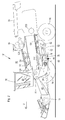
- a concave 132 and below the separating section 128, a separation grate 134 is arranged below the threshing section 126.
- a screw conveyor 140 conveys the grain falling down through the concave 132 to the rear and to the prepurifying screen 72, while the rear conveyor floor 42 conveys the crop falling down through the separating rack 134 forward and in a case step where a grain flow sensor 68a is disposed , emits on the Vorthesessieb 72.
- Another or alternative grain flow sensor 68b is mounted in the rear third of the conveyor floor 42, analogous to the grain flow sensor 68 'of FIG FIG. 1 ,
- the grain stream sensor 68a detects the entire grain flow separated by the separator formed by the separation section 128 and the separation grate 134.
- the grain flow sensor 68b approximately detects the grain stream deposited in the rear third of the separator.
- the operation of the loss measurement device with the control unit 74, the display device 76, the grain flow sensor 68a and / or 68b, and the total grain flow sensor 78 is the same as that of the embodiment of FIG. 1 ,
Landscapes
- Life Sciences & Earth Sciences (AREA)
- Environmental Sciences (AREA)
- Threshing Machine Elements (AREA)
Applications Claiming Priority (1)
| Application Number | Priority Date | Filing Date | Title |
|---|---|---|---|
| DE102013214984.0A DE102013214984A1 (de) | 2013-07-31 | 2013-07-31 | Anordnung zur Verlustmessung in einem Mähdrescher |
Publications (2)
| Publication Number | Publication Date |
|---|---|
| EP2845461A1 true EP2845461A1 (fr) | 2015-03-11 |
| EP2845461B1 EP2845461B1 (fr) | 2018-01-10 |
Family
ID=50943210
Family Applications (1)
| Application Number | Title | Priority Date | Filing Date |
|---|---|---|---|
| EP14172884.0A Active EP2845461B1 (fr) | 2013-07-31 | 2014-06-18 | Agencement de mesure de perte dans une moissonneuse-batteuse |
Country Status (3)
| Country | Link |
|---|---|
| US (1) | US20150080069A1 (fr) |
| EP (1) | EP2845461B1 (fr) |
| DE (1) | DE102013214984A1 (fr) |
Cited By (1)
| Publication number | Priority date | Publication date | Assignee | Title |
|---|---|---|---|---|
| EP3446559A1 (fr) * | 2017-08-23 | 2019-02-27 | Deere & Company | Mesure d'écoulement de grain vers un dispositif de nettoyage |
Families Citing this family (9)
| Publication number | Priority date | Publication date | Assignee | Title |
|---|---|---|---|---|
| US9345197B2 (en) * | 2013-05-10 | 2016-05-24 | Agco Corporation | Combine harvester with even crop distribution |
| US10334781B2 (en) * | 2015-08-20 | 2019-07-02 | Cnh Industrial America Llc | Side shake rate based on machine throughputs |
| US10729065B2 (en) * | 2015-09-10 | 2020-08-04 | Deere & Company | Augmented crop loss sensing |
| US11083137B2 (en) * | 2018-05-01 | 2021-08-10 | Deere & Company | Return pan grain presentation to a sensor |
| GB201820714D0 (en) * | 2018-12-19 | 2019-01-30 | Agco Int Gmbh | Grain cleaning system and method of controlling such |
| US12225849B2 (en) * | 2021-09-03 | 2025-02-18 | Cnh Industrial America Llc | Active loss monitor for a harvester |
| DE102022116228A1 (de) * | 2022-06-29 | 2024-01-04 | Deere & Company | Sensoranordnung zur Erfassung von Eigenschaften eines Korn und Verunreinigungen umfassenden Gemischs in einer Reinigungseinrichtung eines Mähdreschers |
| US12310285B2 (en) | 2023-02-27 | 2025-05-27 | Deere & Company | Agricultural operation evaluation system and method |
| DE102023110536A1 (de) * | 2023-04-25 | 2024-10-31 | Deere & Company | Sensoranordnung für einen Mähdrescher |
Citations (10)
| Publication number | Priority date | Publication date | Assignee | Title |
|---|---|---|---|---|
| GB1157337A (en) * | 1966-12-05 | 1969-07-09 | Fortschritt Veb K | Methods Of, and Apparatus For, Measuring Grain Losses in Threshing Mechanisms |
| US3606745A (en) * | 1969-09-08 | 1971-09-21 | Massey Ferguson Ind Ltd | Grain flow rate monitor |
| GB1401878A (en) * | 1971-12-23 | 1975-08-06 | Fahr Ag Maschf | Device for measuring grain loss in combine harvesters |
| DE2448745A1 (de) | 1974-10-12 | 1976-04-22 | Claas Maschf Gmbh Geb | Koerner-sensor fuer maehdrescher |
| WO1980001532A1 (fr) * | 1979-02-05 | 1980-08-07 | Int Harvester Co | Detection de pertes de grains dans une moissonneuse-batteuse |
| US4951031A (en) | 1988-04-26 | 1990-08-21 | Ford New Holland, Inc. | Method and apparatus for measuring grain loss in harvesting machines |
| DE10162354A1 (de) | 2001-12-18 | 2003-07-03 | Claas Selbstfahr Erntemasch | Verfahren zur Verlustbestimmung an landwirtschaftlichen Erntemaschinen |
| DE102005026608A1 (de) | 2005-06-09 | 2007-01-04 | Deere & Company, Moline | Reinigungseinrichtung für einen Mähdrescher |
| EP2005813A1 (fr) * | 2007-06-22 | 2008-12-24 | CLAAS Selbstfahrende Erntemaschinen GmbH | Moissonneuse agricole automobile dotée d'un dispositif de mesure de perte |
| EP2055176A1 (fr) | 2007-10-31 | 2009-05-06 | Deere & Company | Couvercle supérieur pour moissonneuse-batteuse rotative axiale disposant d'une transition conique |
Family Cites Families (5)
| Publication number | Priority date | Publication date | Assignee | Title |
|---|---|---|---|---|
| US3939846A (en) * | 1974-06-27 | 1976-02-24 | Vladimir Kirillovich Drozhzhin | Device for monitoring and controlling the relative flows and losses of grain in a grain combine thresher |
| US4036065A (en) * | 1976-05-11 | 1977-07-19 | Senstek Ltd. | Grain loss monitor |
| US5046362A (en) * | 1988-04-26 | 1991-09-10 | Ford New Holland, Inc. | Grain loss monitors for harvesting machines |
| GB0604860D0 (en) * | 2006-03-10 | 2006-04-19 | Cnh Belgium Nv | Improvements in or relating to material stream sensors |
| DE102011052282A1 (de) * | 2011-07-29 | 2013-01-31 | Claas Selbstfahrende Erntemaschinen Gmbh | Reinigungssensor zur Steuerung der Erntegut- und Gebläsedruckverteilung |
-
2013
- 2013-07-31 DE DE102013214984.0A patent/DE102013214984A1/de not_active Withdrawn
-
2014
- 2014-06-18 EP EP14172884.0A patent/EP2845461B1/fr active Active
- 2014-07-31 US US14/448,754 patent/US20150080069A1/en not_active Abandoned
Patent Citations (10)
| Publication number | Priority date | Publication date | Assignee | Title |
|---|---|---|---|---|
| GB1157337A (en) * | 1966-12-05 | 1969-07-09 | Fortschritt Veb K | Methods Of, and Apparatus For, Measuring Grain Losses in Threshing Mechanisms |
| US3606745A (en) * | 1969-09-08 | 1971-09-21 | Massey Ferguson Ind Ltd | Grain flow rate monitor |
| GB1401878A (en) * | 1971-12-23 | 1975-08-06 | Fahr Ag Maschf | Device for measuring grain loss in combine harvesters |
| DE2448745A1 (de) | 1974-10-12 | 1976-04-22 | Claas Maschf Gmbh Geb | Koerner-sensor fuer maehdrescher |
| WO1980001532A1 (fr) * | 1979-02-05 | 1980-08-07 | Int Harvester Co | Detection de pertes de grains dans une moissonneuse-batteuse |
| US4951031A (en) | 1988-04-26 | 1990-08-21 | Ford New Holland, Inc. | Method and apparatus for measuring grain loss in harvesting machines |
| DE10162354A1 (de) | 2001-12-18 | 2003-07-03 | Claas Selbstfahr Erntemasch | Verfahren zur Verlustbestimmung an landwirtschaftlichen Erntemaschinen |
| DE102005026608A1 (de) | 2005-06-09 | 2007-01-04 | Deere & Company, Moline | Reinigungseinrichtung für einen Mähdrescher |
| EP2005813A1 (fr) * | 2007-06-22 | 2008-12-24 | CLAAS Selbstfahrende Erntemaschinen GmbH | Moissonneuse agricole automobile dotée d'un dispositif de mesure de perte |
| EP2055176A1 (fr) | 2007-10-31 | 2009-05-06 | Deere & Company | Couvercle supérieur pour moissonneuse-batteuse rotative axiale disposant d'une transition conique |
Cited By (2)
| Publication number | Priority date | Publication date | Assignee | Title |
|---|---|---|---|---|
| EP3446559A1 (fr) * | 2017-08-23 | 2019-02-27 | Deere & Company | Mesure d'écoulement de grain vers un dispositif de nettoyage |
| US10512217B2 (en) | 2017-08-23 | 2019-12-24 | Deere & Company | Metering flow of grain to a cleaning device |
Also Published As
| Publication number | Publication date |
|---|---|
| DE102013214984A1 (de) | 2015-02-05 |
| US20150080069A1 (en) | 2015-03-19 |
| EP2845461B1 (fr) | 2018-01-10 |
Similar Documents
| Publication | Publication Date | Title |
|---|---|---|
| EP2845461B1 (fr) | Agencement de mesure de perte dans une moissonneuse-batteuse | |
| EP3662741B1 (fr) | Machine de travail agricole ainsi que procédé de fonctionnement d'une machine de travail agricole | |
| EP2517549B1 (fr) | Agencement et procédé de détection de la quantité de plantes sur un champ | |
| EP2761984B1 (fr) | Capteur d'oscillations | |
| DE102008006882B4 (de) | Erntemaschinenkombination zur Pflanzenresteverwertung | |
| EP2591654B1 (fr) | Agencement et procédé destinés à la documentation automatique de situations lors d'un travail agricole | |
| EP1350424B1 (fr) | Moisonneuse-batteuse avec dispositif de guidage de paille motorisé ajustable | |
| EP1344444B1 (fr) | Dispositif de détection de la présence de flux de produits dans une moissonneuse | |
| DE60021711T2 (de) | Kondensor für Erntevorrichtung | |
| EP3597027B1 (fr) | Moissonneuse-batteuse doté d'un convoyeur incliné pourvu de rouleau de déviation inférieur réglable | |
| DE102008043377A1 (de) | Messanordnung zur spektroskopischen Untersuchung und Durchsatzerfassung eines Erntegutstroms | |
| DE102007046678A1 (de) | Landwirtschaftliches Arbeitsfahrzeug | |
| EP1266558A2 (fr) | Convoyeur élévateur muni d'un capteur de force pour détecter le débit d' une moissonneuse-bateuse | |
| EP1862055A2 (fr) | Dispositif de répartition destiné à la répartition d'épinards sortant d'une hacheuse | |
| DE102014102221B4 (de) | Verfahren und Steuerungssystem zum Betreiben eines Feldhäckslers sowie Feldhäcksler | |
| DE3709242A1 (de) | Reinigungsvorrichtung fuer maehdrescher | |
| EP2848113B1 (fr) | Dispositif de nettoyage pour une moissonneuse-batteuse | |
| EP2774474B1 (fr) | Moissonneuse-batteuse | |
| EP3072378B1 (fr) | Système capteur de flux de grains pour moissonneuse-batteuse | |
| EP3797577B1 (fr) | Moissonneuse-batteuse pourvue de capteur de grains restants | |
| DE1965025B1 (de) | Anordnung zum Nachdreschen des die Reinigungsvorrichtung einer Dreschmaschine oder eines Maehdreschers unausgedroschen durchlaufenden Gutes | |
| EP4442102A1 (fr) | Procédé et dispositif de traitement assisté par ordinateur d'une carte de rendement électronique | |
| DE10359398B3 (de) | Erntegutbergungseinrichtung mit Abstreifelementen | |
| DE102021110556A1 (de) | Mähdrescher sowie Verfahren zum Betreiben eines Mähdreschers | |
| DE102024118178A1 (de) | Sensoranordnung zur Erfassung von Körnern in einem Körner und Nichtkornbestandteile enthaltenden Materialstrom in einem Mähdrescher |
Legal Events
| Date | Code | Title | Description |
|---|---|---|---|
| 17P | Request for examination filed |
Effective date: 20140618 |
|
| AK | Designated contracting states |
Kind code of ref document: A1 Designated state(s): AL AT BE BG CH CY CZ DE DK EE ES FI FR GB GR HR HU IE IS IT LI LT LU LV MC MK MT NL NO PL PT RO RS SE SI SK SM TR |
|
| AX | Request for extension of the european patent |
Extension state: BA ME |
|
| PUAI | Public reference made under article 153(3) epc to a published international application that has entered the european phase |
Free format text: ORIGINAL CODE: 0009012 |
|
| R17P | Request for examination filed (corrected) |
Effective date: 20150911 |
|
| RBV | Designated contracting states (corrected) |
Designated state(s): AL AT BE BG CH CY CZ DE DK EE ES FI FR GB GR HR HU IE IS IT LI LT LU LV MC MK MT NL NO PL PT RO RS SE SI SK SM TR |
|
| 17Q | First examination report despatched |
Effective date: 20160509 |
|
| GRAP | Despatch of communication of intention to grant a patent |
Free format text: ORIGINAL CODE: EPIDOSNIGR1 |
|
| INTG | Intention to grant announced |
Effective date: 20170811 |
|
| GRAS | Grant fee paid |
Free format text: ORIGINAL CODE: EPIDOSNIGR3 |
|
| GRAA | (expected) grant |
Free format text: ORIGINAL CODE: 0009210 |
|
| AK | Designated contracting states |
Kind code of ref document: B1 Designated state(s): AL AT BE BG CH CY CZ DE DK EE ES FI FR GB GR HR HU IE IS IT LI LT LU LV MC MK MT NL NO PL PT RO RS SE SI SK SM TR |
|
| REG | Reference to a national code |
Ref country code: CH Ref legal event code: EP Ref country code: AT Ref legal event code: REF Ref document number: 961403 Country of ref document: AT Kind code of ref document: T Effective date: 20180115 |
|
| REG | Reference to a national code |
Ref country code: IE Ref legal event code: FG4D Free format text: LANGUAGE OF EP DOCUMENT: GERMAN |
|
| REG | Reference to a national code |
Ref country code: DE Ref legal event code: R096 Ref document number: 502014006869 Country of ref document: DE |
|
| REG | Reference to a national code |
Ref country code: NL Ref legal event code: MP Effective date: 20180110 |
|
| PG25 | Lapsed in a contracting state [announced via postgrant information from national office to epo] |
Ref country code: NL Free format text: LAPSE BECAUSE OF FAILURE TO SUBMIT A TRANSLATION OF THE DESCRIPTION OR TO PAY THE FEE WITHIN THE PRESCRIBED TIME-LIMIT Effective date: 20180110 |
|
| PG25 | Lapsed in a contracting state [announced via postgrant information from national office to epo] |
Ref country code: NO Free format text: LAPSE BECAUSE OF FAILURE TO SUBMIT A TRANSLATION OF THE DESCRIPTION OR TO PAY THE FEE WITHIN THE PRESCRIBED TIME-LIMIT Effective date: 20180410 Ref country code: LT Free format text: LAPSE BECAUSE OF FAILURE TO SUBMIT A TRANSLATION OF THE DESCRIPTION OR TO PAY THE FEE WITHIN THE PRESCRIBED TIME-LIMIT Effective date: 20180110 Ref country code: ES Free format text: LAPSE BECAUSE OF FAILURE TO SUBMIT A TRANSLATION OF THE DESCRIPTION OR TO PAY THE FEE WITHIN THE PRESCRIBED TIME-LIMIT Effective date: 20180110 Ref country code: HR Free format text: LAPSE BECAUSE OF FAILURE TO SUBMIT A TRANSLATION OF THE DESCRIPTION OR TO PAY THE FEE WITHIN THE PRESCRIBED TIME-LIMIT Effective date: 20180110 Ref country code: CY Free format text: LAPSE BECAUSE OF FAILURE TO SUBMIT A TRANSLATION OF THE DESCRIPTION OR TO PAY THE FEE WITHIN THE PRESCRIBED TIME-LIMIT Effective date: 20180110 Ref country code: FI Free format text: LAPSE BECAUSE OF FAILURE TO SUBMIT A TRANSLATION OF THE DESCRIPTION OR TO PAY THE FEE WITHIN THE PRESCRIBED TIME-LIMIT Effective date: 20180110 |
|
| PG25 | Lapsed in a contracting state [announced via postgrant information from national office to epo] |
Ref country code: GR Free format text: LAPSE BECAUSE OF FAILURE TO SUBMIT A TRANSLATION OF THE DESCRIPTION OR TO PAY THE FEE WITHIN THE PRESCRIBED TIME-LIMIT Effective date: 20180411 Ref country code: IS Free format text: LAPSE BECAUSE OF FAILURE TO SUBMIT A TRANSLATION OF THE DESCRIPTION OR TO PAY THE FEE WITHIN THE PRESCRIBED TIME-LIMIT Effective date: 20180510 Ref country code: PL Free format text: LAPSE BECAUSE OF FAILURE TO SUBMIT A TRANSLATION OF THE DESCRIPTION OR TO PAY THE FEE WITHIN THE PRESCRIBED TIME-LIMIT Effective date: 20180110 Ref country code: LV Free format text: LAPSE BECAUSE OF FAILURE TO SUBMIT A TRANSLATION OF THE DESCRIPTION OR TO PAY THE FEE WITHIN THE PRESCRIBED TIME-LIMIT Effective date: 20180110 Ref country code: SE Free format text: LAPSE BECAUSE OF FAILURE TO SUBMIT A TRANSLATION OF THE DESCRIPTION OR TO PAY THE FEE WITHIN THE PRESCRIBED TIME-LIMIT Effective date: 20180110 Ref country code: BG Free format text: LAPSE BECAUSE OF FAILURE TO SUBMIT A TRANSLATION OF THE DESCRIPTION OR TO PAY THE FEE WITHIN THE PRESCRIBED TIME-LIMIT Effective date: 20180410 Ref country code: RS Free format text: LAPSE BECAUSE OF FAILURE TO SUBMIT A TRANSLATION OF THE DESCRIPTION OR TO PAY THE FEE WITHIN THE PRESCRIBED TIME-LIMIT Effective date: 20180110 |
|
| PG25 | Lapsed in a contracting state [announced via postgrant information from national office to epo] |
Ref country code: MT Free format text: LAPSE BECAUSE OF FAILURE TO SUBMIT A TRANSLATION OF THE DESCRIPTION OR TO PAY THE FEE WITHIN THE PRESCRIBED TIME-LIMIT Effective date: 20180110 |
|
| REG | Reference to a national code |
Ref country code: DE Ref legal event code: R097 Ref document number: 502014006869 Country of ref document: DE |
|
| PG25 | Lapsed in a contracting state [announced via postgrant information from national office to epo] |
Ref country code: EE Free format text: LAPSE BECAUSE OF FAILURE TO SUBMIT A TRANSLATION OF THE DESCRIPTION OR TO PAY THE FEE WITHIN THE PRESCRIBED TIME-LIMIT Effective date: 20180110 Ref country code: AL Free format text: LAPSE BECAUSE OF FAILURE TO SUBMIT A TRANSLATION OF THE DESCRIPTION OR TO PAY THE FEE WITHIN THE PRESCRIBED TIME-LIMIT Effective date: 20180110 Ref country code: RO Free format text: LAPSE BECAUSE OF FAILURE TO SUBMIT A TRANSLATION OF THE DESCRIPTION OR TO PAY THE FEE WITHIN THE PRESCRIBED TIME-LIMIT Effective date: 20180110 |
|
| PLBE | No opposition filed within time limit |
Free format text: ORIGINAL CODE: 0009261 |
|
| STAA | Information on the status of an ep patent application or granted ep patent |
Free format text: STATUS: NO OPPOSITION FILED WITHIN TIME LIMIT |
|
| PG25 | Lapsed in a contracting state [announced via postgrant information from national office to epo] |
Ref country code: CZ Free format text: LAPSE BECAUSE OF FAILURE TO SUBMIT A TRANSLATION OF THE DESCRIPTION OR TO PAY THE FEE WITHIN THE PRESCRIBED TIME-LIMIT Effective date: 20180110 Ref country code: SM Free format text: LAPSE BECAUSE OF FAILURE TO SUBMIT A TRANSLATION OF THE DESCRIPTION OR TO PAY THE FEE WITHIN THE PRESCRIBED TIME-LIMIT Effective date: 20180110 Ref country code: DK Free format text: LAPSE BECAUSE OF FAILURE TO SUBMIT A TRANSLATION OF THE DESCRIPTION OR TO PAY THE FEE WITHIN THE PRESCRIBED TIME-LIMIT Effective date: 20180110 Ref country code: SK Free format text: LAPSE BECAUSE OF FAILURE TO SUBMIT A TRANSLATION OF THE DESCRIPTION OR TO PAY THE FEE WITHIN THE PRESCRIBED TIME-LIMIT Effective date: 20180110 |
|
| 26N | No opposition filed |
Effective date: 20181011 |
|
| REG | Reference to a national code |
Ref country code: CH Ref legal event code: PL |
|
| GBPC | Gb: european patent ceased through non-payment of renewal fee |
Effective date: 20180618 |
|
| PG25 | Lapsed in a contracting state [announced via postgrant information from national office to epo] |
Ref country code: SI Free format text: LAPSE BECAUSE OF FAILURE TO SUBMIT A TRANSLATION OF THE DESCRIPTION OR TO PAY THE FEE WITHIN THE PRESCRIBED TIME-LIMIT Effective date: 20180110 |
|
| REG | Reference to a national code |
Ref country code: IE Ref legal event code: MM4A |
|
| PG25 | Lapsed in a contracting state [announced via postgrant information from national office to epo] |
Ref country code: LU Free format text: LAPSE BECAUSE OF NON-PAYMENT OF DUE FEES Effective date: 20180618 Ref country code: MC Free format text: LAPSE BECAUSE OF FAILURE TO SUBMIT A TRANSLATION OF THE DESCRIPTION OR TO PAY THE FEE WITHIN THE PRESCRIBED TIME-LIMIT Effective date: 20180110 |
|
| PG25 | Lapsed in a contracting state [announced via postgrant information from national office to epo] |
Ref country code: GB Free format text: LAPSE BECAUSE OF NON-PAYMENT OF DUE FEES Effective date: 20180618 Ref country code: CH Free format text: LAPSE BECAUSE OF NON-PAYMENT OF DUE FEES Effective date: 20180630 Ref country code: IE Free format text: LAPSE BECAUSE OF NON-PAYMENT OF DUE FEES Effective date: 20180618 Ref country code: FR Free format text: LAPSE BECAUSE OF NON-PAYMENT OF DUE FEES Effective date: 20180630 Ref country code: LI Free format text: LAPSE BECAUSE OF NON-PAYMENT OF DUE FEES Effective date: 20180630 |
|
| PG25 | Lapsed in a contracting state [announced via postgrant information from national office to epo] |
Ref country code: TR Free format text: LAPSE BECAUSE OF FAILURE TO SUBMIT A TRANSLATION OF THE DESCRIPTION OR TO PAY THE FEE WITHIN THE PRESCRIBED TIME-LIMIT Effective date: 20180110 |
|
| PG25 | Lapsed in a contracting state [announced via postgrant information from national office to epo] |
Ref country code: HU Free format text: LAPSE BECAUSE OF FAILURE TO SUBMIT A TRANSLATION OF THE DESCRIPTION OR TO PAY THE FEE WITHIN THE PRESCRIBED TIME-LIMIT; INVALID AB INITIO Effective date: 20140618 Ref country code: PT Free format text: LAPSE BECAUSE OF FAILURE TO SUBMIT A TRANSLATION OF THE DESCRIPTION OR TO PAY THE FEE WITHIN THE PRESCRIBED TIME-LIMIT Effective date: 20180110 |
|
| PG25 | Lapsed in a contracting state [announced via postgrant information from national office to epo] |
Ref country code: MK Free format text: LAPSE BECAUSE OF NON-PAYMENT OF DUE FEES Effective date: 20180110 |
|
| REG | Reference to a national code |
Ref country code: AT Ref legal event code: MM01 Ref document number: 961403 Country of ref document: AT Kind code of ref document: T Effective date: 20190618 |
|
| PG25 | Lapsed in a contracting state [announced via postgrant information from national office to epo] |
Ref country code: AT Free format text: LAPSE BECAUSE OF NON-PAYMENT OF DUE FEES Effective date: 20190618 |
|
| PGFP | Annual fee paid to national office [announced via postgrant information from national office to epo] |
Ref country code: IT Payment date: 20220621 Year of fee payment: 9 |
|
| PG25 | Lapsed in a contracting state [announced via postgrant information from national office to epo] |
Ref country code: IT Free format text: LAPSE BECAUSE OF NON-PAYMENT OF DUE FEES Effective date: 20230618 |
|
| PGFP | Annual fee paid to national office [announced via postgrant information from national office to epo] |
Ref country code: DE Payment date: 20250521 Year of fee payment: 12 |
|
| PGFP | Annual fee paid to national office [announced via postgrant information from national office to epo] |
Ref country code: BE Payment date: 20250627 Year of fee payment: 12 |