EP2803951A1 - Détermination de la topologie pour des matériaux en vrac - Google Patents
Détermination de la topologie pour des matériaux en vrac Download PDFInfo
- Publication number
- EP2803951A1 EP2803951A1 EP13168357.5A EP13168357A EP2803951A1 EP 2803951 A1 EP2803951 A1 EP 2803951A1 EP 13168357 A EP13168357 A EP 13168357A EP 2803951 A1 EP2803951 A1 EP 2803951A1
- Authority
- EP
- European Patent Office
- Prior art keywords
- main emission
- signal strength
- echo
- determining
- bulk material
- Prior art date
- Legal status (The legal status is an assumption and is not a legal conclusion. Google has not performed a legal analysis and makes no representation as to the accuracy of the status listed.)
- Granted
Links
Images




Classifications
-
- G—PHYSICS
- G01—MEASURING; TESTING
- G01S—RADIO DIRECTION-FINDING; RADIO NAVIGATION; DETERMINING DISTANCE OR VELOCITY BY USE OF RADIO WAVES; LOCATING OR PRESENCE-DETECTING BY USE OF THE REFLECTION OR RERADIATION OF RADIO WAVES; ANALOGOUS ARRANGEMENTS USING OTHER WAVES
- G01S13/00—Systems using the reflection or reradiation of radio waves, e.g. radar systems; Analogous systems using reflection or reradiation of waves whose nature or wavelength is irrelevant or unspecified
- G01S13/02—Systems using reflection of radio waves, e.g. primary radar systems; Analogous systems
-
- G—PHYSICS
- G01—MEASURING; TESTING
- G01F—MEASURING VOLUME, VOLUME FLOW, MASS FLOW OR LIQUID LEVEL; METERING BY VOLUME
- G01F23/00—Indicating or measuring liquid level or level of fluent solid material, e.g. indicating in terms of volume or indicating by means of an alarm
- G01F23/22—Indicating or measuring liquid level or level of fluent solid material, e.g. indicating in terms of volume or indicating by means of an alarm by measuring physical variables, other than linear dimensions, pressure or weight, dependent on the level to be measured, e.g. by difference of heat transfer of steam or water
- G01F23/28—Indicating or measuring liquid level or level of fluent solid material, e.g. indicating in terms of volume or indicating by means of an alarm by measuring physical variables, other than linear dimensions, pressure or weight, dependent on the level to be measured, e.g. by difference of heat transfer of steam or water by measuring the variations of parameters of electromagnetic or acoustic waves applied directly to the liquid or fluent solid material
- G01F23/284—Electromagnetic waves
-
- G—PHYSICS
- G01—MEASURING; TESTING
- G01S—RADIO DIRECTION-FINDING; RADIO NAVIGATION; DETERMINING DISTANCE OR VELOCITY BY USE OF RADIO WAVES; LOCATING OR PRESENCE-DETECTING BY USE OF THE REFLECTION OR RERADIATION OF RADIO WAVES; ANALOGOUS ARRANGEMENTS USING OTHER WAVES
- G01S13/00—Systems using the reflection or reradiation of radio waves, e.g. radar systems; Analogous systems using reflection or reradiation of waves whose nature or wavelength is irrelevant or unspecified
- G01S13/02—Systems using reflection of radio waves, e.g. primary radar systems; Analogous systems
- G01S13/06—Systems determining position data of a target
- G01S13/42—Simultaneous measurement of distance and other co-ordinates
-
- G—PHYSICS
- G01—MEASURING; TESTING
- G01S—RADIO DIRECTION-FINDING; RADIO NAVIGATION; DETERMINING DISTANCE OR VELOCITY BY USE OF RADIO WAVES; LOCATING OR PRESENCE-DETECTING BY USE OF THE REFLECTION OR RERADIATION OF RADIO WAVES; ANALOGOUS ARRANGEMENTS USING OTHER WAVES
- G01S13/00—Systems using the reflection or reradiation of radio waves, e.g. radar systems; Analogous systems using reflection or reradiation of waves whose nature or wavelength is irrelevant or unspecified
- G01S13/88—Radar or analogous systems specially adapted for specific applications
Definitions
- the present invention relates to level measurement.
- the invention relates to a measuring device for determining the topology of a bulk material, the use of a measuring device for determining a volume flow of a bulk material, the use of a measuring device for determining the mass of a bulk material, a method for determining the topology of a bulk material, a program element and a computer-readable medium ,
- Bulk goods that are stored in a container or are located on a conveyor belt generally have an irregular, uneven surface. In particular, it may lead to the formation of a bulk cone or a discharge hopper.
- level gauges often determine the level inaccurate if only the distance to a single point on the product surface is determined.
- a measuring device for determining a bulk material which has an antenna arrangement, an echo curve generation unit, an adjusting device and an evaluation unit.
- the antenna arrangement serves to emit a transmission signal in a main emission direction of the antenna arrangement and to receive the transmission signal which is reflected at least on one surface of the bulk material.
- the reflected and received by the antenna arrangement or received transmission signal can also be referred to as a received signal.
- the echo curve generation unit is designed to generate an echo curve from the reflected transmission signal received by the antenna arrangement.
- the echo curve in this case reflects the signal strength or the amplitude of the reflected transmission signal over a distance measuring range of the measuring device.
- the echo curve depicts the dependence of the amplitude of the received, reflected transmission signal on the path length which the corresponding signal component has traveled since the transmission of the transmission signal until its reception by the antenna.
- such an echo curve has a maximum (peak), which is due to the reflection of the transmission signal at the product surface. There may be other maxima contained in the echo curve, which are due to reflections on impurities in the container, etc.
- the measuring device or at least its antenna is controllable by means of the adjusting device, so that the main emission direction of the antenna arrangement can be changed with the aid of the adjusting device, so that a series of echo curves can be generated under different main emission directions.
- a single, mechanically or electronically "pivotable" antenna can be provided.
- no antenna array is required.
- an electronic adjustment of the antenna for example, an array of individual antennas is combined to form a total radiating device.
- topology of the bulk material surface can be determined.
- the term "topology" of the bulk material surface or of the bulk material here is to be understood as meaning the surface profile, that is to say the surface profile of the bulk material surface.
- the surface run can be determined along a line by one-dimensional scanning of the surface (where the particular surface profile is a plane, vertical cut through the surface of the bulk material) or, in contrast to the aforementioned one-dimensional scanning of the surface, by a two-dimensional one Scan the surface. In this case, this involves determining the topology of the bulk material surface in three dimensions.
- the coordinates of such a measuring point are to be understood below as the angles characterizing the main emission direction, under which the corresponding echo curve was generated, as well as the position (the "location") of the greatest signal strength in the echo curve.
- the magnitude of the signal strength is the amplitude of the echo curve at the location of the largest signal strength to understand. This "location" corresponds to the distance corresponding to the largest signal strength.
- a plurality of echo curves are respectively recorded at a different angle (that is, under a different main emission direction of the antenna arrangement).
- the main radiation direction of the antenna arrangement can be controlled mechanically by suitably adjusting the antenna arrangement and / or a reflector the transmission signal is reflected on its way from the antenna to the bulk material surface. It is also possible to electronically adjust the main emission direction, for example by providing a correspondingly controlled antenna array.
- the first range cell of the echo curves is defined and then for each echo curve the maximum of the echo curve in that range cell is identified. Next, it is determined which maximum of the different echo curves is the largest maximum and its coordinates and size are determined. These steps are then performed for more range cells. Depending on whether the main emission direction of the antenna has been changed in one spatial direction or in two spatial directions, a cut line or a three-dimensional representation of the bulk material surface can then be calculated therefrom.
- the evaluation unit creates a matrix which contains the locations corresponding to the maximum maxima of the signal strength for each range cell and their coordinates (distance, main emission direction).
- the evaluation unit determines, using the data obtained in the steps described above, the fill level of the bulk material in a container and / or the bulk material volume of the bulk material.
- the adjusting device for changing the main emission direction of the antenna arrangement is designed in two dimensions.
- the adjusting device for changing the main emission direction of the antenna arrangement is carried out with the aid of a mechanical adjustment device with the aid of which the orientation of the antenna arrangement can be adjusted mechanically.
- the adjusting device for changing the main emission direction of the antenna arrangement comprises a reflector and a mechanical adjusting device for changing the position of the reflector and thus for changing the main emission direction of the antenna arrangement.
- both the antenna alignment and the reflector can be adjusted by means of the adjusting device.
- the measuring device is designed as a level measuring device.
- the meter can be designed as a pulse radar device or FMCW (Frequency Modulated Continuous Wave) level meter.
- the use of a measuring device described above and below for determining the mass of a bulk material is specified.
- a method for determining the topology of a bulk material in which a transmission signal is emitted in a main emission direction of the antenna arrangement and the transmission signal, which is reflected at least on a surface of the bulk material Antenna arrangement is received. Then, an echo curve is generated from the reflected and received by the antenna array transmission signal, which reflects the signal strength of the reflected transmission signal over a distance measuring range of the measuring device. Then the main emission direction of the antenna arrangement is changed, so that further echo curves are generated under different main emission directions.
- a program element that, when executed on a processor of a meter, causes the meter to perform the steps described above and below.
- a computer-readable medium having stored thereon a program element that, when executed on the processor of a meter, causes the meter to perform the steps described above and below.
- the program element may be part of a software that is stored on a processor of the measuring device.
- the invention also relates to a program element which, by means of an update, causes an existing program to use the invention.
- the present invention is used in particular in the field of level measuring devices, but also an application in the field of object monitoring or mass flow detection is possible. It can be seen as a key aspect of the invention to extend level measurement techniques which merely determine the distance to a single point on a product surface such that detection of topology of a surface becomes possible. Especially in bulk material applications, this can result in significantly better measurement results, regardless of how the topology data is to be evaluated in further calculation steps (conceivable: volume flow measurement on conveyor belts, mass detection in vessels ).
- Fig. 1 shows a typical situation in level measurement in bulk solids applications.
- a conventional fill level measuring device 101 emits a signal 103 in the direction of the medium to be measured via a transmitting / receiving unit 102.
- the signal 103 is reflected at different locations 104, 105 of the product surface and, after a corresponding period of time, returns to the level meter 101, where it is received in a suitable manner and is usually converted into an echo curve 108.
- the echo curve 108 shows a very wide echo between the distance d 1 106 and the distance d 2 107. This very wide echo is also called echo band. It results from the overlay a plurality of individual reflections of the transmission signal 103 on the surface of the bulk material to be measured.
- Fig. 2 illustrates the emergence of multiple echoes from a single line of sight (Hauptabstrahlraum) of the level measuring device 101. Due to the structure of the level measuring device 101 and in particular the geometry of the transmitting / receiving antenna 102 results for the different spatial directions, a variable sensitivity of the sensor, which also in Fig. 2 illustrated directional characteristic 201 is indicated.
- the graphically clarified incomplete focusing of the signals means that, in addition to the reflector R2 202 present in the main beam direction, the somewhat adjacent reflector R1 203 is likewise detected by measurement. Based on the echo curve 204, the two echoes 205, 206 of the reflectors 202, 203 are clearly visible.
- Fig. 3 shows - initially in a two-dimensional plane - a sequence of measurements for carrying out the method according to the invention.
- the fill level measuring device 301 according to the invention is aligned by means of a suitable mechanical construction in an adjustable direction on the reflectors R1 203 and R2 202.
- the echo 302 of the reflector R1 203 is imaged with maximum amplitude, since it is just in the main beam direction of the sensor 301 located.
- Reflector R2 202 is based on the current orientation of the sensor next to the main beam direction, which explains its much smaller echo 303.
- Fig. 4 now illustrates the transition to a continuously distributed reflection surface 401 of a bulk material pile.
- the method according to the invention is first shown in a two-dimensional embodiment.
- the surface 401 of the Schütthalde from the sensor from five different viewing directions ( ⁇ 0 , ⁇ 1 , ⁇ 2 , ⁇ 3 , ⁇ 4 ), the main emission directions 410, 411, 412, 413, 414, measured.
- the echo curves 402, 403, 404, 405, 406 detected thereby are first stored in a suitable memory.
- Fig. 5 shows an associated flowchart.
- FIG. 6 to FIG. 10 show important intermediate results in the execution of the procedure.
- the process starts in step S5101.
- Fig. 6 and Fig. 8 show the distance cell 801 defined in this way.
- the maximum curve 701 arises from the fact that for each angle ( ⁇ 0 , ⁇ 1 , ⁇ 2 , ⁇ 3 , ⁇ 4 ), the maximum amplitude (ie the signal strength) of the associated echo curve 402, 403, 404, 405, 406 in the predefined distance range 801 searched and entered as a support point (702, 703, ...) of the maximum curve 701.
- step S5202 the local maxima on the maximum curve 701 are now determined.
- a local maximum M1 704 results.
- the angle coordinates of the local maximum M1 704 are determined.
- the angle coordinate is merely r 1 + r 2 2 ⁇ ⁇ 2 . because the measurement is only two-dimensional.
- an elevation angle is additionally determined here as a third coordinate.
- step S5206 It is now checked whether the result matrix 802 is already occupied at the specific coordinate. Since this is not the case, the maximum M1 becomes at the coordinate r 1 + r 2 2 ⁇ ⁇ 2 in the result matrix 802 in step S5207 ( Fig. 8 , 803).
- the maximum at the respectively first vacant location to the left and right of the detected location of the maximum is entered (S5210, S5211). In the present case would be in occupied position r 1 + r 2 2 ⁇ ⁇ 2 a double entry at positions r 1 + r 2 2 ⁇ ⁇ 1 and r 1 + r 2 2 ⁇ ⁇ 3 respectively.
- step S5104 it is now checked whether all the range cells of interest have already been processed. If this is not the case, then in step S5105 the next distance cell is selected and evaluated in the same way.
- FIG. 9 shows the resulting maximum functions 901, 902, 903, 904.
- the determined interpolation points 803, 905, 906, 907, 908 produce an image of the topology of the bulk material surface 401. If required, the position of further interpolation points can be approximated by known interpolation methods. Furthermore, by known conversion methods, the result matrix (802) can be converted from the polar coordinate representation into a representation with Cartesian coordinates.
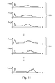
- Fig. 11 shows an associated measurement situation for the acquisition of the necessary echo curves.
- the fill level measuring device 1300 is rotatably and adjustably mounted both in the azimuth direction ( ⁇ ) and in the elevation direction ( ⁇ ).
- the topology of the surface 1302 of a bulk material pile to be determined is in Fig. 13 also shown.
- Fig. 11 shows by way of example the echo curves recorded here.
- the region of interest for the angles ⁇ i is traversed.
- the echo curves 1103 recorded in this process are stored in the memory 1306 of the fill level measuring device.
- the elevation angle is changed to ⁇ 1 , whereupon in turn echo curves 1104 are detected over the angular direction ⁇ .
- the method thus detects a plurality of echo curves from the regions of interest for ⁇ and ⁇ .
- the filling level measuring device comprises a memory 1306 for holding the values of four respectively three-dimensional matrices A Work , A ⁇ , A ⁇ , A Final (cf. Fig. 13 ).
- step 1202 the result matrix A Final 802 is emptied.
- step S1203 equivalent to step S5102
- FIG. 5 defines a range cell, which in the three-dimensional case represents a segment of a spherical shell.
- step 1204 the contents of the result matrix A Final are taken over into the local work matrix A Work .
- step S5200 a conventional evaluation including steps S5201 to S5211 corresponding to the flowchart of FIG Figure 5 performed over two dimensions. This calculation is realized using the work matrix A Work .
- steps S1206 and S1207 the evaluation is achieved by further angles of ⁇ . After these process steps, the three-dimensional work matrix A Work is occupied with the maxima in the angular direction ⁇ .
- step S1208 the three-dimensional work matrix A Work occupied in this way is copied and stored in a separate location in the memory.
- the copied matrix may henceforth be denoted by A ⁇ .
- all entries are removed from the original matrix.
- step S1209 the contents of the result matrix A Final are taken over into the local work matrix A Work .
- steps S1210 to S1212 the evaluation is carried out at a respectively defined azimuth angle ⁇ according to the method already described above. After the end of these process steps, the three-dimensional result matrix is occupied by the maxima in the angular direction ⁇ . The contents of the resulting matrix are taken over into the matrix A ⁇ held in memory.
- step S1213 the result matrix A ⁇ is merged with the result matrix A ⁇ created in step S1208.
- final result matrix A Final a corresponding entry is taken exactly if both the matrix A ⁇ and the matrix A ⁇ at the coordinate r 1 + r 2 2 ⁇ ⁇ i ⁇ ⁇ i contains an entry.
- step S1214 and step S1215 if necessary, the next removal cell (which may be in the form of a spherical shell) is changed.
- step S1216 After all the removal cells of interest have been processed, the method ends in step S1216.
- the entries of the result matrix produce an image of the topology of the bulk material surface 1302. If required, the position of further support points can be approximated by using known interpolation methods. Furthermore, by using known conversion methods, the result matrix A Final can be converted from the polar coordinate representation into a representation with Cartesian coordinates.
- Fig. 13 shows a measuring arrangement according to an embodiment of the invention.
- a container 1309 is provided in which a bulk material 1302 is located. It may also be possible to use the invention in conjunction with dumps without containers.
- a level gauge 1300 which is movably mounted on the ceiling portion of the container.
- an adjusting device is provided, which has a ball joint 1307, 1308, which permits an adjustment of the orientation of the level measuring device along the angle ⁇ and ⁇ .
- the adjusting device has an actuator (not shown), which is connected to the processor 1304 of the level measuring device, so that the main emission direction 1305 of the antenna arrangement 1301 of the level measuring device can be adjusted fully automatically.
- the reflected transmission signal received by the antenna is transmitted to the echo curve generation unit 1303, which generates an echo curve therefrom, which is then transferred to the processor, that is to say to the evaluation unit of the level measurement device.
- the processor 1304 is connected to a memory unit 1306, on which the echo curves and the topology data, from which the topology of the bulk material surface can be calculated, are stored.
- Fig. 14 shows a measuring arrangement according to an embodiment of the invention.
- a reflector 1401 is provided, which is located in the main emission direction 1305 of the antenna arrangement 1301 of the fill level measuring device and can be adjusted via the adjusting device 1403, 1404, which may also be designed in the form of a ball joint.
- the stationary part 1403 of the adjusting device is attached to the container wall 1402, for example.
- the level gauge as well as in the embodiment of Fig. 13 be attached to the container wall via its own adjusting device 1307, 1308.
- the level gauge can be pivoted only within a plane and the mirror is pivotable in a second plane, so that the bulk material surface can be completely scanned.
- the topology of a bulk material surface can be determined with a single antenna.
- the antenna according to the invention may be selected from the group of horn antennas, rod antennas, patch antennas or any array antennas.
- a conventional level gauge By comparing a plurality of echo curves in a defined area or a defined spherical shell (distance cell), the lateral resolution a conventional level gauge can be further improved without the need for multiple sensors or multiple mounting positions.
Landscapes
- Engineering & Computer Science (AREA)
- Radar, Positioning & Navigation (AREA)
- Remote Sensing (AREA)
- Physics & Mathematics (AREA)
- General Physics & Mathematics (AREA)
- Electromagnetism (AREA)
- Computer Networks & Wireless Communication (AREA)
- Thermal Sciences (AREA)
- Fluid Mechanics (AREA)
- Radar Systems Or Details Thereof (AREA)
- Geophysics And Detection Of Objects (AREA)
Priority Applications (4)
| Application Number | Priority Date | Filing Date | Title |
|---|---|---|---|
| EP13168357.5A EP2803951B1 (fr) | 2013-05-17 | 2013-05-17 | Détermination de la topologie pour des matériaux en vrac |
| HUE13168357A HUE049876T2 (hu) | 2013-05-17 | 2013-05-17 | Topológiameghatározás ömlesztett termékekhez |
| US14/276,536 US9739877B2 (en) | 2013-05-17 | 2014-05-13 | Topology determination for bulk materials |
| CN201410211358.9A CN104165671B (zh) | 2013-05-17 | 2014-05-19 | 散装材料的拓扑确定 |
Applications Claiming Priority (1)
| Application Number | Priority Date | Filing Date | Title |
|---|---|---|---|
| EP13168357.5A EP2803951B1 (fr) | 2013-05-17 | 2013-05-17 | Détermination de la topologie pour des matériaux en vrac |
Publications (2)
| Publication Number | Publication Date |
|---|---|
| EP2803951A1 true EP2803951A1 (fr) | 2014-11-19 |
| EP2803951B1 EP2803951B1 (fr) | 2020-02-26 |
Family
ID=48470771
Family Applications (1)
| Application Number | Title | Priority Date | Filing Date |
|---|---|---|---|
| EP13168357.5A Active EP2803951B1 (fr) | 2013-05-17 | 2013-05-17 | Détermination de la topologie pour des matériaux en vrac |
Country Status (4)
| Country | Link |
|---|---|
| US (1) | US9739877B2 (fr) |
| EP (1) | EP2803951B1 (fr) |
| CN (1) | CN104165671B (fr) |
| HU (1) | HUE049876T2 (fr) |
Cited By (6)
| Publication number | Priority date | Publication date | Assignee | Title |
|---|---|---|---|---|
| DE102015104229A1 (de) * | 2015-03-20 | 2016-09-22 | Hauk & Sasko Ingenieurgesellschaft Mbh | System und Verfahren zum Betrieb einer Halde |
| DE102016110712A1 (de) * | 2016-06-10 | 2017-12-14 | Michael Sauer | Vorrichtung zur Füllstandsüberwachung |
| DE102016124859A1 (de) | 2016-12-19 | 2018-06-21 | Krohne Messtechnik Gmbh | Verfahren zur Bestimmung der Geschwindigkeit einer Schüttgutoberfläche, Füllstandmessgerät und Verwendung eines Füllstandmessgeräts |
| EP3578930A1 (fr) * | 2018-05-30 | 2019-12-11 | VEGA Grieshaber KG | Procédé de surveillance de la bande transporteuse |
| WO2023041278A1 (fr) * | 2021-09-14 | 2023-03-23 | Endress+Hauser SE+Co. KG | Dispositif de mesure de niveau de remplissage |
| DE102023117993A1 (de) | 2023-07-07 | 2025-01-09 | Ifm Electronic Gmbh | Verfahren zur Höhenprofilerkennung, Spurführung und Volumenbestimmung bei der Umsetzung von Kompostmieten |
Families Citing this family (14)
| Publication number | Priority date | Publication date | Assignee | Title |
|---|---|---|---|---|
| DE102013213340A1 (de) * | 2013-07-08 | 2015-01-08 | Vega Grieshaber Kg | Bestimmung einer Distanz und einer Fließgeschwindigkeit eines Mediums |
| DE102013213346A1 (de) * | 2013-07-08 | 2015-01-08 | Vega Grieshaber Kg | Bestimmung von Pegel und Fließgeschwindigkeit eines Mediums |
| DE102013213345A1 (de) * | 2013-07-08 | 2015-01-08 | Vega Grieshaber Kg | Universelle Messdatenerfassung in Gewässern |
| US9658096B2 (en) * | 2014-06-30 | 2017-05-23 | Rosemount Tank Radar Ab | Radar level gauge inclination system |
| EP3115779B1 (fr) * | 2015-07-06 | 2023-07-26 | ABB Schweiz AG | Système et procédé pour mesurer une vitesse de propagation de signaux dans un milieu liquide ou gazeux |
| WO2017084701A1 (fr) | 2015-11-17 | 2017-05-26 | Vega Grieshaber Kg | Dispositif d'antenne et procédé pour faire fonctionner un dispositif d'antenne |
| JP6850173B2 (ja) * | 2017-03-24 | 2021-03-31 | 京セラ株式会社 | 電磁波検出装置、プログラム、および電磁波検出システム |
| RU2653578C1 (ru) * | 2017-06-08 | 2018-05-11 | Акционерное общество "ЛИМАКО" | Радиолокационный уровнемер для измерения объема сыпучих продуктов в резервуарах |
| US10935651B2 (en) * | 2017-12-15 | 2021-03-02 | Google Llc | Radar angular ambiguity resolution |
| US11573311B2 (en) | 2018-04-05 | 2023-02-07 | Google Llc | Smart-device-based radar system performing angular estimation using machine learning |
| CN109975799A (zh) * | 2019-03-13 | 2019-07-05 | 谭伟 | 一种雷达识别材料的方法及其系统 |
| EP3792198B1 (fr) * | 2019-09-12 | 2024-02-28 | Rosemount Tank Radar AB | Surveillance de toit flottant |
| DE102020124300A1 (de) | 2020-09-17 | 2022-03-17 | Endress+Hauser SE+Co. KG | Winkelauflösendes Füllstandsmessgerät |
| CN112782694B (zh) * | 2021-01-22 | 2023-06-30 | 重庆秦嵩科技有限公司 | 一种基于多核dsp的雷达信号处理方法及系统 |
Citations (8)
| Publication number | Priority date | Publication date | Assignee | Title |
|---|---|---|---|---|
| US4219814A (en) * | 1978-12-26 | 1980-08-26 | Rca Corporation | Scanning radar |
| DE3735905A1 (de) * | 1987-10-23 | 1989-05-03 | Hipp Johann F | Verfahren und vorrichtung zur volumenstrommessung auf bandfoerderern mittels laser-entfernungsprofilscanner |
| DE4339441A1 (de) * | 1993-11-19 | 1995-05-24 | Incatronic Phoenix Mestechnik | Verfahren zur Messung des Füllgrads von mit Füllgut gefüllten Behältern |
| US6986294B2 (en) * | 2000-02-17 | 2006-01-17 | Bintech Lllp | Bulk materials management apparatus and method |
| FR2907546A1 (fr) * | 2006-10-19 | 2008-04-25 | Crealyst Sarl | Systeme de determination du relief d'une surface de remplissage de granules dans un reacteur petrochimique |
| WO2010003656A1 (fr) * | 2008-07-08 | 2010-01-14 | Indurad Gmbh | Procédé d'évaluation de signaux radar d'un système de détection radar installé en milieux industriels |
| EP2315045A1 (fr) * | 2009-10-22 | 2011-04-27 | Sick Ag | Mesure des éloignements ou des modifications d'éloignement |
| US20130060528A1 (en) * | 2011-05-20 | 2013-03-07 | James Portman | System and method for determining a quantity of bulk material |
Family Cites Families (7)
| Publication number | Priority date | Publication date | Assignee | Title |
|---|---|---|---|---|
| DE102004041857A1 (de) | 2004-08-27 | 2006-03-02 | Endress + Hauser Gmbh + Co. Kg | Verfahren und Vorrichtung zum Ausrichten eines Messgerätes |
| EP2090387A1 (fr) | 2008-01-18 | 2009-08-19 | Corus Staal BV | Procédé et appareil pour surveiller les surfaces de laitier et métal fondu dans un moule |
| EP2128576B1 (fr) | 2008-05-27 | 2016-12-28 | VEGA Grieshaber KG | Procédé de détection de double parole basé sur les propriétés acoustiques spectrales |
| US8224594B2 (en) * | 2008-09-18 | 2012-07-17 | Enraf B.V. | Apparatus and method for dynamic peak detection, identification, and tracking in level gauging applications |
| DE102009001010B4 (de) * | 2008-12-30 | 2023-06-15 | Endress+Hauser SE+Co. KG | Verfahren zur Ermittlung und Überwachung des Füllstands eines Mediums in einem Behälter nach einem Laufzeitmessverfahren |
| EP2226615B1 (fr) * | 2009-03-02 | 2018-08-22 | VEGA Grieshaber KG | Mesures de niveaux de remplissage à l'aide d'une évaluation d'une courbe d'écho |
| DE102011075826A1 (de) | 2011-05-13 | 2012-11-15 | Endress + Hauser Gmbh + Co. Kg | Überwachung einer produktions- oder fördertechnischen Umgebung mittels Radar |
-
2013
- 2013-05-17 EP EP13168357.5A patent/EP2803951B1/fr active Active
- 2013-05-17 HU HUE13168357A patent/HUE049876T2/hu unknown
-
2014
- 2014-05-13 US US14/276,536 patent/US9739877B2/en active Active
- 2014-05-19 CN CN201410211358.9A patent/CN104165671B/zh active Active
Patent Citations (8)
| Publication number | Priority date | Publication date | Assignee | Title |
|---|---|---|---|---|
| US4219814A (en) * | 1978-12-26 | 1980-08-26 | Rca Corporation | Scanning radar |
| DE3735905A1 (de) * | 1987-10-23 | 1989-05-03 | Hipp Johann F | Verfahren und vorrichtung zur volumenstrommessung auf bandfoerderern mittels laser-entfernungsprofilscanner |
| DE4339441A1 (de) * | 1993-11-19 | 1995-05-24 | Incatronic Phoenix Mestechnik | Verfahren zur Messung des Füllgrads von mit Füllgut gefüllten Behältern |
| US6986294B2 (en) * | 2000-02-17 | 2006-01-17 | Bintech Lllp | Bulk materials management apparatus and method |
| FR2907546A1 (fr) * | 2006-10-19 | 2008-04-25 | Crealyst Sarl | Systeme de determination du relief d'une surface de remplissage de granules dans un reacteur petrochimique |
| WO2010003656A1 (fr) * | 2008-07-08 | 2010-01-14 | Indurad Gmbh | Procédé d'évaluation de signaux radar d'un système de détection radar installé en milieux industriels |
| EP2315045A1 (fr) * | 2009-10-22 | 2011-04-27 | Sick Ag | Mesure des éloignements ou des modifications d'éloignement |
| US20130060528A1 (en) * | 2011-05-20 | 2013-03-07 | James Portman | System and method for determining a quantity of bulk material |
Cited By (7)
| Publication number | Priority date | Publication date | Assignee | Title |
|---|---|---|---|---|
| DE102015104229A1 (de) * | 2015-03-20 | 2016-09-22 | Hauk & Sasko Ingenieurgesellschaft Mbh | System und Verfahren zum Betrieb einer Halde |
| DE102016110712A1 (de) * | 2016-06-10 | 2017-12-14 | Michael Sauer | Vorrichtung zur Füllstandsüberwachung |
| DE102016124859A1 (de) | 2016-12-19 | 2018-06-21 | Krohne Messtechnik Gmbh | Verfahren zur Bestimmung der Geschwindigkeit einer Schüttgutoberfläche, Füllstandmessgerät und Verwendung eines Füllstandmessgeräts |
| EP3578930A1 (fr) * | 2018-05-30 | 2019-12-11 | VEGA Grieshaber KG | Procédé de surveillance de la bande transporteuse |
| US11255956B2 (en) | 2018-05-30 | 2022-02-22 | Vega Grieshaber Kg | Method for measuring the flow velocity of a medium |
| WO2023041278A1 (fr) * | 2021-09-14 | 2023-03-23 | Endress+Hauser SE+Co. KG | Dispositif de mesure de niveau de remplissage |
| DE102023117993A1 (de) | 2023-07-07 | 2025-01-09 | Ifm Electronic Gmbh | Verfahren zur Höhenprofilerkennung, Spurführung und Volumenbestimmung bei der Umsetzung von Kompostmieten |
Also Published As
| Publication number | Publication date |
|---|---|
| EP2803951B1 (fr) | 2020-02-26 |
| US9739877B2 (en) | 2017-08-22 |
| HUE049876T2 (hu) | 2020-11-30 |
| CN104165671B (zh) | 2019-01-15 |
| US20140340259A1 (en) | 2014-11-20 |
| CN104165671A (zh) | 2014-11-26 |
Similar Documents
| Publication | Publication Date | Title |
|---|---|---|
| EP2803951B1 (fr) | Détermination de la topologie pour des matériaux en vrac | |
| EP2803952B1 (fr) | Commande d'appareil de mesure pour la détermination de la topologie d'une surface d'un matériau en vrac | |
| EP2128576B1 (fr) | Procédé de détection de double parole basé sur les propriétés acoustiques spectrales | |
| EP3377864B1 (fr) | Dispositif d'antenne et procédé pour faire fonctionner un dispositif d'antenne | |
| EP3105939B1 (fr) | Système de mesure et procédé pour détecter des propriétés d'un objet | |
| DE19937723C2 (de) | Verfahren und Vorrichtung zur Bestimmung eines Höhenwinkelfehlers eines mehrstrahligen Radar-Sensors | |
| EP3278067B1 (fr) | Compteur de niveau et procede de determination de la topologie d'une surface de remplissage | |
| DE3808173C2 (fr) | ||
| EP3309523A1 (fr) | Jauge destinée à déterminer une topologie d'une surface de matériau de remplissage | |
| DE4344509B4 (de) | Verfahren zur Messung der akustischen Rückstreueigenschaft von Gewässerböden | |
| WO2013045232A1 (fr) | Dispositif à radar et procédé pour produire une caractéristique de groupe d'un radar | |
| DE112004002165T5 (de) | Radarsystem | |
| DE69620752T2 (de) | System zur erkennung und vermessung von bewegungen der atmosphäre | |
| DE102018217173A1 (de) | Reflektorsystem in einem radarzielsimulator zum testen einer funktionsfähigkeit eines radarsensors und verfahren zum testen einer funktionsfähigkeit eines radarsensors | |
| EP3137857B1 (fr) | Mesure de niveau par détermination de la topologie de surface et correction du centre de rotation | |
| DE102022103147A1 (de) | Verfahren und vorrichtung zum verfolgen eines objekts unter verwendung eines lidar-sensors und aufzeichnungsmedium, welches ein programm speichert, um das verfahren auszuführen | |
| DE112009005399T5 (de) | Radarvorrichtung | |
| DE102021100695B4 (de) | Verfahren zum Betrieb eines Topologie-erfassenden Radarsystems innerhalb eines Behälters | |
| DE102016213033A1 (de) | Verfahren und Vorrichtung zum Bestimmen der ortsaufgelösten Füllstandshöhe in einem Schüttgutbehälter | |
| WO2020200768A1 (fr) | Barrière réfléchissante à micro-ondes multidimensionnelle | |
| DE102019216879B3 (de) | FMCW-Radarmessgerät | |
| EP3105556A1 (fr) | Détermination d'état de remplissage et de topologie | |
| DE102009042969A1 (de) | Verfahren und Vorrichtung zum Bestimmen der Position eines Wasserfahrzeugs | |
| DE102021126142A1 (de) | Kalibriervorrichtungsanordnung für eine Kraftfahrzeugradarvorrichtung, Kalibriervorrichtung und Kalibrierverfahren | |
| DE102016224962B3 (de) | Synthetik-Apertur-Radarverfahren und Synthetik-Apertur-Radarsystem |
Legal Events
| Date | Code | Title | Description |
|---|---|---|---|
| PUAI | Public reference made under article 153(3) epc to a published international application that has entered the european phase |
Free format text: ORIGINAL CODE: 0009012 |
|
| 17P | Request for examination filed |
Effective date: 20130517 |
|
| AK | Designated contracting states |
Kind code of ref document: A1 Designated state(s): AL AT BE BG CH CY CZ DE DK EE ES FI FR GB GR HR HU IE IS IT LI LT LU LV MC MK MT NL NO PL PT RO RS SE SI SK SM TR |
|
| AX | Request for extension of the european patent |
Extension state: BA ME |
|
| R17P | Request for examination filed (corrected) |
Effective date: 20150211 |
|
| RBV | Designated contracting states (corrected) |
Designated state(s): AL AT BE BG CH CY CZ DE DK EE ES FI FR GB GR HR HU IE IS IT LI LT LU LV MC MK MT NL NO PL PT RO RS SE SI SK SM TR |
|
| STAA | Information on the status of an ep patent application or granted ep patent |
Free format text: STATUS: EXAMINATION IS IN PROGRESS |
|
| 17Q | First examination report despatched |
Effective date: 20181203 |
|
| GRAP | Despatch of communication of intention to grant a patent |
Free format text: ORIGINAL CODE: EPIDOSNIGR1 |
|
| STAA | Information on the status of an ep patent application or granted ep patent |
Free format text: STATUS: GRANT OF PATENT IS INTENDED |
|
| INTG | Intention to grant announced |
Effective date: 20190917 |
|
| GRAS | Grant fee paid |
Free format text: ORIGINAL CODE: EPIDOSNIGR3 |
|
| GRAA | (expected) grant |
Free format text: ORIGINAL CODE: 0009210 |
|
| STAA | Information on the status of an ep patent application or granted ep patent |
Free format text: STATUS: THE PATENT HAS BEEN GRANTED |
|
| AK | Designated contracting states |
Kind code of ref document: B1 Designated state(s): AL AT BE BG CH CY CZ DE DK EE ES FI FR GB GR HR HU IE IS IT LI LT LU LV MC MK MT NL NO PL PT RO RS SE SI SK SM TR |
|
| REG | Reference to a national code |
Ref country code: GB Ref legal event code: FG4D Free format text: NOT ENGLISH |
|
| REG | Reference to a national code |
Ref country code: CH Ref legal event code: EP |
|
| REG | Reference to a national code |
Ref country code: AT Ref legal event code: REF Ref document number: 1238210 Country of ref document: AT Kind code of ref document: T Effective date: 20200315 |
|
| REG | Reference to a national code |
Ref country code: IE Ref legal event code: FG4D Free format text: LANGUAGE OF EP DOCUMENT: GERMAN |
|
| REG | Reference to a national code |
Ref country code: DE Ref legal event code: R096 Ref document number: 502013014330 Country of ref document: DE |
|
| REG | Reference to a national code |
Ref country code: NL Ref legal event code: FP |
|
| PG25 | Lapsed in a contracting state [announced via postgrant information from national office to epo] |
Ref country code: FI Free format text: LAPSE BECAUSE OF FAILURE TO SUBMIT A TRANSLATION OF THE DESCRIPTION OR TO PAY THE FEE WITHIN THE PRESCRIBED TIME-LIMIT Effective date: 20200226 Ref country code: RS Free format text: LAPSE BECAUSE OF FAILURE TO SUBMIT A TRANSLATION OF THE DESCRIPTION OR TO PAY THE FEE WITHIN THE PRESCRIBED TIME-LIMIT Effective date: 20200226 Ref country code: NO Free format text: LAPSE BECAUSE OF FAILURE TO SUBMIT A TRANSLATION OF THE DESCRIPTION OR TO PAY THE FEE WITHIN THE PRESCRIBED TIME-LIMIT Effective date: 20200526 |
|
| REG | Reference to a national code |
Ref country code: LT Ref legal event code: MG4D |
|
| PG25 | Lapsed in a contracting state [announced via postgrant information from national office to epo] |
Ref country code: IS Free format text: LAPSE BECAUSE OF FAILURE TO SUBMIT A TRANSLATION OF THE DESCRIPTION OR TO PAY THE FEE WITHIN THE PRESCRIBED TIME-LIMIT Effective date: 20200626 Ref country code: BG Free format text: LAPSE BECAUSE OF FAILURE TO SUBMIT A TRANSLATION OF THE DESCRIPTION OR TO PAY THE FEE WITHIN THE PRESCRIBED TIME-LIMIT Effective date: 20200526 Ref country code: LV Free format text: LAPSE BECAUSE OF FAILURE TO SUBMIT A TRANSLATION OF THE DESCRIPTION OR TO PAY THE FEE WITHIN THE PRESCRIBED TIME-LIMIT Effective date: 20200226 Ref country code: SE Free format text: LAPSE BECAUSE OF FAILURE TO SUBMIT A TRANSLATION OF THE DESCRIPTION OR TO PAY THE FEE WITHIN THE PRESCRIBED TIME-LIMIT Effective date: 20200226 Ref country code: GR Free format text: LAPSE BECAUSE OF FAILURE TO SUBMIT A TRANSLATION OF THE DESCRIPTION OR TO PAY THE FEE WITHIN THE PRESCRIBED TIME-LIMIT Effective date: 20200527 Ref country code: HR Free format text: LAPSE BECAUSE OF FAILURE TO SUBMIT A TRANSLATION OF THE DESCRIPTION OR TO PAY THE FEE WITHIN THE PRESCRIBED TIME-LIMIT Effective date: 20200226 |
|
| PG25 | Lapsed in a contracting state [announced via postgrant information from national office to epo] |
Ref country code: PT Free format text: LAPSE BECAUSE OF FAILURE TO SUBMIT A TRANSLATION OF THE DESCRIPTION OR TO PAY THE FEE WITHIN THE PRESCRIBED TIME-LIMIT Effective date: 20200719 Ref country code: ES Free format text: LAPSE BECAUSE OF FAILURE TO SUBMIT A TRANSLATION OF THE DESCRIPTION OR TO PAY THE FEE WITHIN THE PRESCRIBED TIME-LIMIT Effective date: 20200226 Ref country code: DK Free format text: LAPSE BECAUSE OF FAILURE TO SUBMIT A TRANSLATION OF THE DESCRIPTION OR TO PAY THE FEE WITHIN THE PRESCRIBED TIME-LIMIT Effective date: 20200226 Ref country code: SK Free format text: LAPSE BECAUSE OF FAILURE TO SUBMIT A TRANSLATION OF THE DESCRIPTION OR TO PAY THE FEE WITHIN THE PRESCRIBED TIME-LIMIT Effective date: 20200226 Ref country code: SM Free format text: LAPSE BECAUSE OF FAILURE TO SUBMIT A TRANSLATION OF THE DESCRIPTION OR TO PAY THE FEE WITHIN THE PRESCRIBED TIME-LIMIT Effective date: 20200226 Ref country code: EE Free format text: LAPSE BECAUSE OF FAILURE TO SUBMIT A TRANSLATION OF THE DESCRIPTION OR TO PAY THE FEE WITHIN THE PRESCRIBED TIME-LIMIT Effective date: 20200226 Ref country code: LT Free format text: LAPSE BECAUSE OF FAILURE TO SUBMIT A TRANSLATION OF THE DESCRIPTION OR TO PAY THE FEE WITHIN THE PRESCRIBED TIME-LIMIT Effective date: 20200226 Ref country code: CZ Free format text: LAPSE BECAUSE OF FAILURE TO SUBMIT A TRANSLATION OF THE DESCRIPTION OR TO PAY THE FEE WITHIN THE PRESCRIBED TIME-LIMIT Effective date: 20200226 Ref country code: RO Free format text: LAPSE BECAUSE OF FAILURE TO SUBMIT A TRANSLATION OF THE DESCRIPTION OR TO PAY THE FEE WITHIN THE PRESCRIBED TIME-LIMIT Effective date: 20200226 |
|
| REG | Reference to a national code |
Ref country code: DE Ref legal event code: R097 Ref document number: 502013014330 Country of ref document: DE |
|
| REG | Reference to a national code |
Ref country code: HU Ref legal event code: AG4A Ref document number: E049876 Country of ref document: HU |
|
| PLBE | No opposition filed within time limit |
Free format text: ORIGINAL CODE: 0009261 |
|
| STAA | Information on the status of an ep patent application or granted ep patent |
Free format text: STATUS: NO OPPOSITION FILED WITHIN TIME LIMIT |
|
| PG25 | Lapsed in a contracting state [announced via postgrant information from national office to epo] |
Ref country code: IT Free format text: LAPSE BECAUSE OF FAILURE TO SUBMIT A TRANSLATION OF THE DESCRIPTION OR TO PAY THE FEE WITHIN THE PRESCRIBED TIME-LIMIT Effective date: 20200226 Ref country code: CH Free format text: LAPSE BECAUSE OF NON-PAYMENT OF DUE FEES Effective date: 20200531 Ref country code: MC Free format text: LAPSE BECAUSE OF FAILURE TO SUBMIT A TRANSLATION OF THE DESCRIPTION OR TO PAY THE FEE WITHIN THE PRESCRIBED TIME-LIMIT Effective date: 20200226 Ref country code: LI Free format text: LAPSE BECAUSE OF NON-PAYMENT OF DUE FEES Effective date: 20200531 |
|
| 26N | No opposition filed |
Effective date: 20201127 |
|
| PG25 | Lapsed in a contracting state [announced via postgrant information from national office to epo] |
Ref country code: SI Free format text: LAPSE BECAUSE OF FAILURE TO SUBMIT A TRANSLATION OF THE DESCRIPTION OR TO PAY THE FEE WITHIN THE PRESCRIBED TIME-LIMIT Effective date: 20200226 Ref country code: PL Free format text: LAPSE BECAUSE OF FAILURE TO SUBMIT A TRANSLATION OF THE DESCRIPTION OR TO PAY THE FEE WITHIN THE PRESCRIBED TIME-LIMIT Effective date: 20200226 |
|
| REG | Reference to a national code |
Ref country code: BE Ref legal event code: MM Effective date: 20200531 |
|
| PG25 | Lapsed in a contracting state [announced via postgrant information from national office to epo] |
Ref country code: LU Free format text: LAPSE BECAUSE OF NON-PAYMENT OF DUE FEES Effective date: 20200517 |
|
| PG25 | Lapsed in a contracting state [announced via postgrant information from national office to epo] |
Ref country code: IE Free format text: LAPSE BECAUSE OF NON-PAYMENT OF DUE FEES Effective date: 20200517 |
|
| PG25 | Lapsed in a contracting state [announced via postgrant information from national office to epo] |
Ref country code: BE Free format text: LAPSE BECAUSE OF NON-PAYMENT OF DUE FEES Effective date: 20200531 |
|
| REG | Reference to a national code |
Ref country code: AT Ref legal event code: MM01 Ref document number: 1238210 Country of ref document: AT Kind code of ref document: T Effective date: 20200517 |
|
| PG25 | Lapsed in a contracting state [announced via postgrant information from national office to epo] |
Ref country code: AT Free format text: LAPSE BECAUSE OF NON-PAYMENT OF DUE FEES Effective date: 20200517 |
|
| PG25 | Lapsed in a contracting state [announced via postgrant information from national office to epo] |
Ref country code: TR Free format text: LAPSE BECAUSE OF FAILURE TO SUBMIT A TRANSLATION OF THE DESCRIPTION OR TO PAY THE FEE WITHIN THE PRESCRIBED TIME-LIMIT Effective date: 20200226 Ref country code: MT Free format text: LAPSE BECAUSE OF FAILURE TO SUBMIT A TRANSLATION OF THE DESCRIPTION OR TO PAY THE FEE WITHIN THE PRESCRIBED TIME-LIMIT Effective date: 20200226 Ref country code: CY Free format text: LAPSE BECAUSE OF FAILURE TO SUBMIT A TRANSLATION OF THE DESCRIPTION OR TO PAY THE FEE WITHIN THE PRESCRIBED TIME-LIMIT Effective date: 20200226 |
|
| PG25 | Lapsed in a contracting state [announced via postgrant information from national office to epo] |
Ref country code: MK Free format text: LAPSE BECAUSE OF FAILURE TO SUBMIT A TRANSLATION OF THE DESCRIPTION OR TO PAY THE FEE WITHIN THE PRESCRIBED TIME-LIMIT Effective date: 20200226 Ref country code: AL Free format text: LAPSE BECAUSE OF FAILURE TO SUBMIT A TRANSLATION OF THE DESCRIPTION OR TO PAY THE FEE WITHIN THE PRESCRIBED TIME-LIMIT Effective date: 20200226 |
|
| P01 | Opt-out of the competence of the unified patent court (upc) registered |
Free format text: CASE NUMBER: UPC_APP_325523/2023 Effective date: 20230523 |
|
| PGFP | Annual fee paid to national office [announced via postgrant information from national office to epo] |
Ref country code: NL Payment date: 20250522 Year of fee payment: 13 |
|
| PGFP | Annual fee paid to national office [announced via postgrant information from national office to epo] |
Ref country code: DE Payment date: 20250519 Year of fee payment: 13 |
|
| PGFP | Annual fee paid to national office [announced via postgrant information from national office to epo] |
Ref country code: GB Payment date: 20250522 Year of fee payment: 13 |
|
| PGFP | Annual fee paid to national office [announced via postgrant information from national office to epo] |
Ref country code: HU Payment date: 20250514 Year of fee payment: 13 Ref country code: FR Payment date: 20250523 Year of fee payment: 13 |