EP2804006B1 - Dispositif destiné à être utilisé avec un compteur d'électricité - Google Patents
Dispositif destiné à être utilisé avec un compteur d'électricité Download PDFInfo
- Publication number
- EP2804006B1 EP2804006B1 EP13167871.6A EP13167871A EP2804006B1 EP 2804006 B1 EP2804006 B1 EP 2804006B1 EP 13167871 A EP13167871 A EP 13167871A EP 2804006 B1 EP2804006 B1 EP 2804006B1
- Authority
- EP
- European Patent Office
- Prior art keywords
- fuse
- circuit
- electricity meter
- meter
- support
- Prior art date
- Legal status (The legal status is an assumption and is not a legal conclusion. Google has not performed a legal analysis and makes no representation as to the accuracy of the status listed.)
- Active
Links
Images


Classifications
-
- G—PHYSICS
- G01—MEASURING; TESTING
- G01R—MEASURING ELECTRIC VARIABLES; MEASURING MAGNETIC VARIABLES
- G01R15/00—Details of measuring arrangements of the types provided for in groups G01R17/00 - G01R29/00, G01R33/00 - G01R33/26 or G01R35/00
- G01R15/14—Adaptations providing voltage or current isolation, e.g. for high-voltage or high-current networks
-
- G—PHYSICS
- G01—MEASURING; TESTING
- G01R—MEASURING ELECTRIC VARIABLES; MEASURING MAGNETIC VARIABLES
- G01R11/00—Electromechanical arrangements for measuring time integral of electric power or current, e.g. of consumption
- G01R11/02—Constructional details
- G01R11/04—Housings; Supporting racks; Arrangements of terminals
-
- G—PHYSICS
- G01—MEASURING; TESTING
- G01R—MEASURING ELECTRIC VARIABLES; MEASURING MAGNETIC VARIABLES
- G01R21/00—Arrangements for measuring electric power or power factor
-
- G—PHYSICS
- G01—MEASURING; TESTING
- G01R—MEASURING ELECTRIC VARIABLES; MEASURING MAGNETIC VARIABLES
- G01R22/00—Arrangements for measuring time integral of electric power or current, e.g. electricity meters
- G01R22/06—Arrangements for measuring time integral of electric power or current, e.g. electricity meters by electronic methods
- G01R22/061—Details of electronic electricity meters
- G01R22/065—Details of electronic electricity meters related to mechanical aspects
-
- H—ELECTRICITY
- H01—ELECTRIC ELEMENTS
- H01H—ELECTRIC SWITCHES; RELAYS; SELECTORS; EMERGENCY PROTECTIVE DEVICES
- H01H85/00—Protective devices in which the current flows through a part of fusible material and this current is interrupted by displacement of the fusible material when this current becomes excessive
- H01H85/02—Details
- H01H85/20—Bases for supporting the fuse; Separate parts thereof
- H01H85/205—Electric connections to contacts on the base
-
- H—ELECTRICITY
- H01—ELECTRIC ELEMENTS
- H01H—ELECTRIC SWITCHES; RELAYS; SELECTORS; EMERGENCY PROTECTIVE DEVICES
- H01H9/00—Details of switching devices, not covered by groups H01H1/00 - H01H7/00
- H01H9/10—Adaptation for built-in fuses
- H01H9/102—Fuses mounted on or constituting the movable contact parts of the switch
Definitions
- the present disclosure relates to a device for use with an electricity meter, for opening and closing circuits in the electricity meter.
- the disclosure also relates to a method of using such a device, as well as to a system incorporating the device together with a main electrical device and an auxiliary electrical device.
- auxiliary devices used with electricity meters are often placed next to the electricity meter.
- electricity meters In the context of smart metering, auxiliary devices used with electricity meters are often placed next to the electricity meter.
- electricity meters In the context of smart metering, auxiliary devices used with electricity meters are often placed next to the electricity meter.
- electricity meters In the context of smart metering, auxiliary devices used with electricity meters are often placed next to the electricity meter.
- electricity meters In the context of smart metering, auxiliary devices used with electricity meters are often placed next to the electricity meter.
- auxiliary device modules In the context of smart metering, auxiliary devices used with electricity meters are often placed next to the electricity meter.
- auxiliary device modules In the context of smart metering, auxiliary devices used with electricity meters are often placed next to the electricity meter.
- additional modules such as gateways, modems, tariff modules or customer information modules must be supplied with mains voltage.
- the electrical connection to these auxiliary devices may be mounted in one of two different ways. Either the electrical connection to the mains is before the electricity meter, or else it is after the meter. In the first case, also known as the unmeasured connection, the meter will not register the consumption of the connected auxiliary device and the consumption will be at the electricity supplier's expense. In the second case, the auxiliary device is connected after the meter, which implies that the consumption will be registered by the electricity meter and therefore at the customer's expense.
- connection depends, among other things, on the power consumption of the connected auxiliary device.
- the choice of connection type is generally given to the technician installing the auxiliary device. However, during the lifetime of the meter it may be desirable to change the connection type between these two states, such that the meter may register the energy consumption of the auxiliary device, or else such that the meter does not register the energy consumption of the auxiliary device. For example, when there is a change in energy supplier, the customer's contract may stipulate that auxiliary devices connected to the meter must be operated at the customer's expense, in which case the connection type may need changing.
- connection to the auxiliary device or devices must be protected by an electrical fuse against over-current.
- Fuses which are generally installed before the electricity meter, must fulfill the requirements to a defined maximum High Breaking Capacity (HBC). If the connection needs to be switched, then typically a jumper located before the meter must be operated to break the connection, after which the fuse may be manually relocated to change the connection type.
- jumpers generally have high restrictions (for example, they must have double isolation) and add expense to the meter setup.
- EP 2209012 discloses an assembly having a connection region provided for an electronic electricity meter, and another connection region provided for a switch and a communication module.
- the two connection regions are provided adjacent to each other.
- a terminal block is provided for connection of phase conductors and neutral conductors, and is arranged at a lower edge in middle of a rectangular base plate that upwardly projects over the former connection region.
- the latter connection region extends over entire vertical length of the base plate.
- US 2012/0276775 discloses an adaptor for connecting a network device.
- the adaptor includes adapter housing.
- the adapter housing further includes a based and a wall such that the wall extends axially from the base.
- the base adapter housing also includes an inner surface and an outer surface.
- the adapter consists of a plurality of socket opening that extend across the base between the inner surface.
- the plurality of socket openings extending axially, the socket opening continue across the inner surface of the base through the first end of the rim and the second end of the rim.
- the adaptor may have a bypass circuit.
- the bypass circuit may allow a network device to get power for a line side of a power meter and the consumer may get power from the load side of the power meter.
- the present disclosure proposes a novel device and method for safely and efficiently changing the connection type.
- the present invention relates to a device and to the use of electrical fuses with the device for connecting auxiliary devices to electricity meters.
- the combination of a device and fuse may protect a connected auxiliary device and may provide the option of selecting the type of electrical connection between two terminals.
- the device may ensure that only one terminal is electrically connected at any given time.
- the selection can be made at mains voltage.
- a device for use with an electricity meter is selectively moveable between first and second positions.
- the device comprises a fuse support capable of holding a fuse in a fuse position.
- the device is arranged such that, when in the first position, the fuse position is located relative to first and second circuits such that when a fuse is held in the fuse support the first circuit is closed and the second circuit is open.
- the device is further arranged such that moving the device from the first to the second position causes the fuse position to be relocated relative to the first and second circuits such that the first circuit is opened and the second circuit is closed.
- the fuse support may be advantageously arranged to hold and retain a fuse in a fuse position.
- a fuse held in the fuse support may effectively be retained with the device and moved simultaneously with the device.
- a fuse held in the fuse support may be arranged to open and close a circuit in the meter, or a circuit connecting the meter to the auxiliary device.
- the first/second circuit opening/closing it should be understood as meaning that the fuse is positioned so as to join two contact points of the circuit in electrical conductance, or else break the electrical connection between the two contact points in the case of the fuse being removed from the circuit.
- the fuse position may be defined as the position taken by a fuse when held in the fuse support.
- the fuse position may be measured from the centre of the fuse when held in the fuse support, or may be defined relative to the ends of the fuse when held in the fuse support.
- the fuse support may take various different forms.
- a fuse may be snap-fitted into the fuse support.
- a more permanent fixture may exist between the fuse and the fuse support.
- the device comprises a fuse cover or similar cover portion for covering the fuse when the device is installed in a meter.
- the device may further comprise a fuse cover for covering a fuse held in the fuse support when the device is used with an electricity meter.
- the device complies with IEC standard 60536: " Classification of the electrical and electronic devices for protection against electrical shock " .
- category PC2 is applicable.
- the device should be designed in a way that it may prevent contact of fingers with live parts (which is an inspection condition according to DIN EN 60529). Whilst the device may take various shapes and forms, its typical dimensions may be in the range of about 5mm x 20mm to about 6.3mm x 32mm. Given such a shape, the device can be located deep enough within the meter housing to meet the requirements of category PC2.
- the device is generally intended to be placed in the electricity meter below a sealable terminal cover to prevent tampering.
- a distance between the fuse position and a top portion of the device may be at least about 8mm (e.g. to provide a minimum safety distance between the fuse and a user's fingers handling the device). This distance may be measured from a centre of a fuse held in the fuse support vertically upwards to a fuse cover at the top of the device.
- the inventive device provides a relatively safe and efficient means of selecting and alternating between two different connection types between an electricity meter and an auxiliary device.
- the device effectively incorporates the dual function of a jumper and a fuse.
- a circuit may effectively be broken and a fuse removed from it in a single step. There is no need to first operate a jumper prior to removal of the fuse.
- a user is less likely to misplace or accidentally drop the fuse during relocation, as it may be safely retained in the device by means of the fuse support holding it in place.
- the device may further comprise first and second supports at either end of a length of the device.
- the fuse position may be located between the first and second supports.
- the device comprises a pair of legs defining ends of the device, the legs being joined by a crossbar or similar fuse cover.
- the fuse cover may offer a measure of protection to the fuse such that when the device is installed in an electricity meter the fuse is hidden from view and reduces the fuse's exposure. The device may therefore prevent someone from accidentally coming into contact with the fuse.
- By positioning the fuse support between the first and second ends it may be made easier to hide the fuse from view by means of the fuse cover or crossbar.
- the fuse support may be arranged such that it extends away from the fuse cover and holds a fuse in a fuse position between the first and second ends or legs of the device, hidden by the fuse cover.
- the legs or supports of the device may furthermore assist in providing a minimum of distance or clearance between the user and the fuse.
- the fuse position may be located between the first support and a midsection, centre or midpoint of the device. This arrangement may be advantageous as the resulting device has a smaller footprint within the meter. For example, a simple rotation of the device through 180° may be sufficient to bring the fuse support from one position to another, without requiring a complete repositioning of the device within the meter. It may be furthermore advantageous with this design to provide a non-conducting member located between the midsection and the second end or supporting leg of the device. The non-conducting member may extend away from the fuse cover. This may ensure that when in either the first or second position only a single circuit is closed as the crossbar effectively prevents the device from being installed in the meter if a fuse is already in use with the circuits.
- the fuse position may be offset from a midsection of the device by a distance less than half a length of a fuse to be held in the fuse support.
- the device may be rotated through 180° in order to move it between the first and second positions. In this case, in the first position the device is effectively a mirror image of itself in the second position. Whilst it may be more difficult in this embodiment to prevent the fuse accidentally interacting with another circuit, the device does not have to be as long as in the example where the fuse position is located between one leg and the midsection.
- the fuse support may be located substantially equidistant from the legs or ends of the device.
- the device may further comprise an informational component inscribed on or attached to the device for indicating a relative orientation of the device.
- the informational component may be disposed on a fuse cover of the device that is visible to a user when the device is installed.
- a user may rapidly determine whether the auxiliary device is connected before or after the meter, and therefore whether or not the meter is registering the auxiliary device's energy consumption.
- the device may be elongate such that the device may define a longitudinal axis.
- the fuse support may be arranged to hold a fuse in the fuse position such that a held fuse is aligned with the longitudinal axis.
- the device may further comprise an outwardly extending member for facilitating removal of the device from an electricity meter when the device is in use with an electricity meter.
- the outwardly extending member or flange may extend away from a fuse cover of the device.
- a screwdriver or other leveraging tool may then be used to prise or otherwise remove the device from an electricity meter.
- a fuse cover of the device When installed in the meter, a fuse cover of the device may be arranged to lie flush with the housing of the meter, and the outwardly extending member or side bar may facilitate removal of the device in such cases.
- the first circuit may connect an electricity meter with an auxiliary device, and when the first circuit is closed the auxiliary device may be connected before the electricity meter such that the electricity meter does not register an electricity consumption of the auxiliary device.
- the second circuit may connect an electricity meter with an auxiliary device, and when the second circuit is closed the auxiliary device may be connected after the electricity meter such that the electricity meter registers an electricity consumption of the auxiliary device.
- a method of selectively opening and closing first and second circuits connecting an electricity meter and an auxiliary device comprises providing a device with a fuse support capable of holding a fuse in a fuse position. The method also comprises engaging a fuse with the fuse support such that the fuse is held in the fuse position. The method also comprises selectively moving the device between first and second positions such that the fuse alternately opens and closes the first and second circuits.
- a user may safely move the device between first and second positions to selectively open and close first and second circuits in the meter, without having to resort to the use of a jumper or the like.
- the fuse may be safely retained by the fuse holder so as to reduce the risk of loss and or damage to the fuse during repositioning.
- the step of selectively moving the device may comprise rotating the device 180° about an axis passing through its centre.
- the axis passes perpendicularly to a fuse cover or crossbar of the device and parallel to a pair of legs of the device, the legs extending away from the crossbar.
- the axis may also be perpendicular to a longitudinal axis defined by a fuse held in the fuse support.
- the fuse In the first position the fuse may connect two circuit points of the first circuit. In the second position the fuse may connect two circuit points of the second circuit. In each of the first and second positions each pair of circuit points may be located between a respective end of the device and a midsection of the device.
- the fuse When the fuse is arranged to contact two circuit points located between a first end or leg of the device and a midsection of the device, there may be less risk of the fuse accidentally contacting the wrong contact points.
- the two contact points of one of the first and second circuits may be adjacent each other.
- the distance separating the two pairs of contact points may be similar to the length of the device, such that it may be necessary to move the device only a small amount when altering the connections between the electricity meter and the auxiliary device.
- the device may simply be rotated 180° to relocate the fuse position
- the fuse In the first position the fuse may connect two circuit points of the first circuit. In the second position the fuse may connect two circuit points of the second circuit.
- a first one of each pair of circuit points may be located between a first end of the device and a midsection of the device.
- the second one of each pair of circuit points may be located between a second end of the device and the midsection of the device.
- This arrangement may be preferable as it provides a device of reduced length.
- the fuse position may be located only slightly offset from the centre of the device, such that rotating the device 180° may result in a relatively small translation of the fuse position, preferably of a distance less than half a length of the fuse.
- each circuit point of one of two circuits may be disposed adjacent a circuit point of the other circuit.
- a system for selectively opening and closing first and second circuits comprising a main electrical device connected to an auxiliary electrical device via the first and second circuits.
- the system further comprises a device according to any of the above-described embodiments. In the first position the first circuit is closed and the second circuit is open. In the second position the first circuit is open and the second circuit is closed.
- the main electrical device may be an electricity meter.
- the auxiliary electrical device When the first circuit is closed the auxiliary electrical device may be connected before the electricity meter such that the electricity meter does not register an electricity consumption of the auxiliary electrical device.
- the auxiliary electrical device When the second circuit is closed the auxiliary electrical device may be connected after the electricity meter such that the electricity meter registers an electricity consumption of the auxiliary electrical device.
- the present invention seeks to provide an improved device for selectively changing connections between an electricity meter and an auxiliary device. Whilst various embodiments of the invention are described below, the invention is not limited to these embodiments, and variations of these embodiments may well fall within the scope of the invention which is to be limited only by the appended claims.
- Figure 1 shows a circuit or connection diagram of a common electricity meter 10 with an auxiliary device 12.
- Lines L1, L2, L3 and N are electrical lines positioned before the meter, with corresponding lines 13 after the meter.
- Two fuse holders, 14 and 16 are connected to meter 10 and auxiliary device 12.
- Fuse holder 14 is connected before meter 10, and fuse holder 16 is connected after meter 10.
- fuse holder 14 is assembled (i.e. if a fuse is inserted or otherwise engaged with fuse holder 14)
- auxiliary device 12 will be connected before meter 10.
- auxiliary device 12 is connected before meter 10
- meter 10 will not register the electricity consumption of auxiliary device 12.
- fuse holder 16 is assembled, then auxiliary device 12 will be connected after meter 10.
- meter 10 will register the electricity consumption of auxiliary device 12. It should be borne in mind that both fuses holders 14 and 16 must not be assembled at the same time, i.e. only one fuse should ever be engaged with the fuse holders, either in fuse holder 14 or in fuse holder 16. Otherwise, the current path of the meter will be by-passed, and the meter will not measure any current along line L3. Of course, in other embodiments fuse holders 14 and 16 may be connected to any of the other lines shown in Figure 1 . Line L3 is merely used as an example.
- fuse holders 14 and 16 are effectively part of two different circuits.
- a first circuit may be held to comprise meter 10, auxiliary device 12 and fuse holder 14, with auxiliary device 12 being electrically positioned before meter 10.
- a second circuit may be held to comprise meter 10, auxiliary device 12 and fuse holder 16, with auxiliary device 12 being electrically positioned after meter 10.
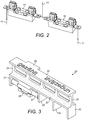
- FIG 2 shows fuse holders 14 and 16 in greater detail.
- electrical fuse holders 14 and 16 are of the Rivet/Eyelet Mount Solder type, and should be placed in the electricity meter. Besides these conventional fuse holders or clips, a type directly soldered onto the PCB is also possible. In other embodiments, fuse holders 14 and 16 may simply be replaced with gaps in the circuit into which fuses may be inserted or otherwise engaged to complete the circuits.
- Line 11 is a connection to the electricity meter (before the meter).
- Line 15 is a connection to the auxiliary device.
- line 17 is a connection to the electricity meter (after the meter).
- Fuse holders 14 and 16 are used with a connection selector such as the one described below in connection with Figure 3 .
- connection selector 20 that may be used to selectively open and close the first and second circuits referred to above.
- Connection selector 20 is preferably made of plastic, although other insulating materials may be used without departing from the scope of the invention.
- Connection selector 20 comprises a pair of opposed legs or uprights 21, 22, extending from a crossbar 23 joining legs 21 and 22. Extending away from crossbar 23 is a fuse cover 24 held at a distance from crossbar 23 by a plurality of supporting members or struts 25.
- fuse cover 24 may be supported at a distance from crossbar 23 using other means. In other embodiments, fuse cover 24 may be removed thereby leaving only crossbar 23.
- the distance separating fuse cover 24 from crossbar 23 is preferably in accordance with touch-protection category PC2.
- Connection selector 20 comprises a fuse support 26 that is arranged to hold a fuse 27 in a fuse position.
- Figure 3 shows connection selector 20 with fuse 27 already held in the fuse position by fuse support 26.
- fuse support 26 takes the form of a pair of jaws into which fuse 27 may be inserted or clipped such that it may be held and retained in frictional engagement with fuse support 26.
- Legs 21 and 22 define first and second ends of connection selector 20.
- Fuse support 26 is located between first leg or end 21 and a centre point, midpoint or midsection 28 of connection selector 20 such that the fuse position is positioned between first end 21 and midsection 28.
- Fuse cover 24 includes a side bar or other projecting flange 29 arranged to facilitate removal of connection selector 20 from an electricity meter. For example, a user may insert a screwdriver or other lever beneath sidebar 29 so as to prise connection selector 20 out of the electricity meter. After removing connection selector 20 from the electricity meter, fuse 27 is disconnected from the circuit it was engaged with whilst remaining held in fuse support 26, and is effectively transported with connection selector 20. Thus, a defective fuse in connection selector 20 may be easily identified and replaced.
- Connection selector 20 further comprises a tamper-proof crossbar 23a extending away from crossbar 23 and between legs 21 and 22. Tamper-proof crossbar 23a may ensure that connection selector 20 may not be engaged with fuse holders (such as fuse holders 14 and 16 described above) if a fuse is already inserted in one of the fuse holders. This avoids the above-mentioned by-passing of the current path, and thereby provides a safety mechanism.
- fuse holders such as fuse holders 14 and 16 described above
- Fuse cover 24 comprises text inscribed into it to indicate a relative orientation of connection selector 20.
- Figure 3 the German words for "counted” and “uncounted” are inscribed, thereby indicating, when connection selector 20 is installed in a meter, whether or not the energy consumption of an auxiliary device is being registered by the electricity meter (e.g. whether the first or second circuit is closed).
- connection selector 20 the counterparts to connection selector 20 are fuse holders 14 and 16 in an electricity meter, which are shown in Figure 2 .
- both electrical fuse holders 14 and 16 are aligned and the distance separating them corresponds approximately to a length of connection selector 20.
- connection selector 20 may be used to connect the auxiliary device to the electricity meter via either the first or second circuit (as in Figure 1 ).
- connection selector 20 may be engaged with fuse holder 12 such that fuse 27 held in fuse support 26 engages with fuse holder 12 and completes the first circuit.
- connection selector 20 may be turned 180° about an axis passing through its midsection (e.g. normal to a longitudinal axis defined by connection selector 20).
- fuse 27 may be relocated from fuse holder 14 to fuse holder 16, thereby opening the first circuit and closing the second circuit.
- connection selector 20 may then be reconnected with the other of fuse holders 14 and 16.
- the labeling or marking on fuse cover 24 indicates the type of connection currently in effect.
- Such labeling can be for example pictograms or inscriptions like “counted” "uncounted, as in Figure 3 .
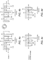
- Figures 4a and 4b show an embodiment of a connection selector 30 moved between two different positions relative to an electricity meter.
- fuse 37 first contacts in Figure 4a two different contact points 41 and 42 of a first circuit.
- Contact points 41 and 42 are adjacent each other and are located between the first end 31 of connection selector 30 and the centre or midsection 38 of connection selector 30.
- Contact points 41 and 42 belong to line L3u and if connected may complete the first circuit such that an auxiliary device is connected before the meter.
- Tamper-proof crossbar 33a is positioned between adjacent contact points 43 and 44 of a second circuit, and prevents connection selector 30 from being positioned as it is in Figure 4a if a fuse were already engaged with contact points 43 and 44.
- connection selector 30 is rotated by 180° such that the fuse position is moved to the position shown in Figure 4b .
- connection selector 30 which is retained in fuse support 36 during the rotation of connection selector 30 now contacts adjacent contact points 43 and 44 of line L3c, belonging to a second circuit. Relocation of connection selector 30 in this manner opens the first circuit and closes the second circuit such that the auxiliary device is connected after the meter. Tamper-proof crossbar 33a is now positioned between contact points 41 and 42 of the first circuit, and prevents connection selector 30 from being positioned as it is in Figure 4b if a fuse were already engaged with contact points 41 and 42.
- connection selector 50 does not comprise a tamper-proof crossbar. Instead, fuse support 56 is slightly offset from the centre or midsection of connection selector 50 such that the fuse position is also offset.
- fuse 57 connects contact points 61 and 62 that are this time on opposite sides of fuse support 56.
- contact points 61 and 62 are part of line L3u belonging to the first circuit. When contact points 61 and 62 are connected, the first circuit is completed such that an auxiliary device is connected before the meter.
- fuse 57 which is retained in fuse support 56 during the rotation of connection selector 50 now contacts two contact points 63 and 64 of line L3c, belonging to a second circuit.
- Contact points 63 and 64 are on opposite sides of fuse support 56. Relocation of connection selector 50 in this manner opens the first circuit and closes the second circuit such that the auxiliary device is connected after meter.
- Figure 5 shows a terminal area of an electricity meter with fuse clips.
- the arrangement of the fuse clips is similar to the arrangement of contact points 61 - 64 shown in Figures 4c and 4d and discussed above.
- Fuse clips 81 and 83 are connected together and lead to a power socket for the auxiliary device.
- Fuse clip 82 is connected to terminal 85 (L3c), whilst fuse clip 84 is connected to terminal 86 (L3u).
- Terminals of lines L3c and L3u, 85 and 86, are shown behind fuse clips 82 and 84, respectively.
- a meter shunt 87 is shown between terminals 85 and 86, and therefore also between fuse clips 82 and 84.
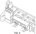
- Figure 6 shows the same terminal area this time with connection selector 50 relative to fuse clips 81 - 84.
- fuse 57 connects fuse clips 81 and 82, thereby closing the second circuit such that the auxiliary device is connected after the meter.
- Fuse 57 is placed asymmetrically relative to connection selector 50 such that when connection selector 50 is rotated through 180° fuse 57 sits in fuse clips 83 and 84, thereby closing the first circuit such that the auxiliary device is connected before the meter.
- connection selector 50 180° degrees about an axis passing through its midsection, fuse clips 81 and 82 are disconnected and fuse clips 83 and 84 are connected, as seen for example in Figures 4c and 4d .
- the device may comprise a fuse support capable of holding a fuse in a fuse position and movable from one position to another without the need for rotation.
- the fuse support may be located equidistant of the first and second ends of the connection selector such that the fuse position may also be located equidistant of the first and second ends.
- the connection selector may then be translated along its longitudinal axis a small amount in order to alternately bring two different pairs of contact points into electrical contact with each other.
- the device may be arranged to hold multiple fuses, such that in some applications the device could be used to selectively open and close more than two circuits.
Landscapes
- Physics & Mathematics (AREA)
- General Physics & Mathematics (AREA)
- Engineering & Computer Science (AREA)
- Power Engineering (AREA)
- Fuses (AREA)
Claims (15)
- Dispositif (20) destiné à être utilisé avec un compteur d'électricité, le dispositif pouvant être déplacé de manière sélective entre une première et une seconde position, et le dispositif comprenant :un support de fusible (26) capable de maintenir un fusible (27) dans une position de fusible, le dispositif (20) étant agencé de telle sorte que, dans la première position, la position du fusible soit située par rapport aux premier et second circuits de sorte que lorsqu'un fusible (27) est maintenu dans le support de fusible (26), le premier circuit soit fermé et le second circuit soit ouvert, et le dispositif (20) étant en outre agencé de sorte que le déplacement du dispositif de la première à la seconde position provoque le déplacement simultané d'un fusible (27) maintenu dans le support de fusible (26) avec le dispositif (20) et provoque le déplacement de la position du fusible par rapport aux premier et second circuits de telle sorte que le premier circuit soit ouvert et que le second circuit soit fermé.
- Dispositif selon la revendication 1, comprenant en outre un couvercle de fusible (24) destiné à recouvrir un fusible (27) maintenu dans le support de fusible (26) lorsque le dispositif est utilisé avec un compteur d'électricité (10).
- Dispositif selon l'une quelconque des revendications précédentes, comprenant en outre des premier et second supports (21, 22) à chaque extrémité d'une longueur du dispositif (20), et dans lequel la position du fusible est située entre les premier et second supports (21, 22).
- Dispositif selon la revendication 3, dans lequel la position du fusible est située entre le premier support (21) et une section médiane (28) du dispositif.
- Dispositif selon la revendication 4, comprenant en outre un élément non conducteur (23a) entre la section médiane (28) et le second support (22).
- Dispositif selon l'une quelconque des revendications précédentes, dans lequel la position du fusible est décalée par rapport à une section médiane (28) du dispositif (20) d'une distance inférieure à la demi-longueur d'un fusible (27) à maintenir dans le support du fusible (26).
- Dispositif selon l'une quelconque des revendications 1 à 3, dans lequel la position du fusible est approximativement équidistante des premier et second supports.
- Dispositif selon l'une quelconque des revendications précédentes, comprenant en outre un élément s'étendant vers l'extérieur (29) pour faciliter le retrait du dispositif (20) d'un compteur d'électricité (10) lorsque le dispositif est utilisé avec un compteur d'électricité.
- Dispositif selon l'une quelconque des revendications précédentes, dans lequel le premier circuit relie un compteur d'électricité (10) et un dispositif auxiliaire (12), et dans lequel, lorsque le premier circuit est fermé, le dispositif auxiliaire (12) est connecté en amont du compteur d'électricité (10) de sorte que le compteur d'électricité (10) n'enregistre pas de consommation d'électricité du dispositif auxiliaire (12).
- Dispositif selon l'une quelconque des revendications précédentes, dans lequel le second circuit relie un compteur d'électricité (10) et un dispositif auxiliaire (12), et dans lequel, lorsque le second circuit est fermé, le dispositif auxiliaire (12) est connecté en aval du compteur d'électricité (10) de sorte que le compteur d'électricité (10) enregistre une consommation d'électricité du dispositif auxiliaire (12) .
- Procédé d'ouverture et de fermeture sélectives du premier et du second circuits reliant un compteur d'électricité (10) et un dispositif auxiliaire (12), comprenant :la fourniture d'un dispositif (20) avec un support de fusible (26) capable de maintenir un fusible (27) dans une position de fusible ;la prise d'un fusible (27) avec le support de fusible (26) de sorte que le fusible soit maintenu dans la position du fusible ; etle déplacement sélectif du dispositif (20) entre les première et seconde positions de sorte que le fusible (27) se déplace simultanément avec le dispositif et ouvre et ferme alternativement les premier et second circuits.
- Procédé selon la revendication 11, dans lequel l'étape consistant à déplacer sélectivement le dispositif (20) comprend la rotation du dispositif de 180 degrés autour d'un axe passant par son centre.
- Procédé selon la revendication 11 ou 12, dans lequel, dans la première position, le fusible (37) connecte deux points de circuit (41, 42) du premier circuit et dans lequel, dans la seconde position, le fusible (37) relie deux points de circuit (43, 44) du second circuit, et dans lequel, dans chacune des première et seconde positions, chaque paire de points de circuit (41, 42 ; 43, 44) est située entre une extrémité respective (31) du dispositif et une section médiane (38) du dispositif.
- Procédé selon la revendication 11 ou 12, dans lequel, dans la première position, le fusible (27) relie deux points de circuit (61, 62) du premier circuit et dans lequel, dans la seconde position, le fusible relie deux points de circuit (63, 64) du second circuit, et dans lequel, dans chacune des première et seconde positions, un premier point de chaque paire de points de circuit est situé entre une première extrémité du dispositif et une section médiane du dispositif, et dans lequel le second de chaque paire de points de circuit est situé entre une seconde extrémité du dispositif et la section médiane du dispositif.
- Système pour ouvrir et fermer sélectivement un premier et un second circuit, comprenant :un dispositif électrique principal (10) connecté à un dispositif électrique auxiliaire (12) par l'intermédiaire du premier et du second circuits ; etun dispositif (20) selon l'une quelconque des revendications 1 à 10, dans lequel, dans la première position, le premier circuit est fermé et le second circuit est ouvert, et dans lequel, dans la seconde position, le premier circuit est ouvert et le second circuit est fermé.
Priority Applications (3)
| Application Number | Priority Date | Filing Date | Title |
|---|---|---|---|
| EP13167871.6A EP2804006B1 (fr) | 2013-05-15 | 2013-05-15 | Dispositif destiné à être utilisé avec un compteur d'électricité |
| PCT/EP2014/059384 WO2014184076A1 (fr) | 2013-05-15 | 2014-05-07 | Dispositif devant être utilisé avec un compteur électrique |
| US14/891,341 US9869700B2 (en) | 2013-05-15 | 2014-05-07 | Device for use with an electricity meter |
Applications Claiming Priority (1)
| Application Number | Priority Date | Filing Date | Title |
|---|---|---|---|
| EP13167871.6A EP2804006B1 (fr) | 2013-05-15 | 2013-05-15 | Dispositif destiné à être utilisé avec un compteur d'électricité |
Publications (2)
| Publication Number | Publication Date |
|---|---|
| EP2804006A1 EP2804006A1 (fr) | 2014-11-19 |
| EP2804006B1 true EP2804006B1 (fr) | 2018-11-07 |
Family
ID=48482913
Family Applications (1)
| Application Number | Title | Priority Date | Filing Date |
|---|---|---|---|
| EP13167871.6A Active EP2804006B1 (fr) | 2013-05-15 | 2013-05-15 | Dispositif destiné à être utilisé avec un compteur d'électricité |
Country Status (3)
| Country | Link |
|---|---|
| US (1) | US9869700B2 (fr) |
| EP (1) | EP2804006B1 (fr) |
| WO (1) | WO2014184076A1 (fr) |
Cited By (1)
| Publication number | Priority date | Publication date | Assignee | Title |
|---|---|---|---|---|
| DE102020122869A1 (de) | 2020-09-01 | 2022-03-03 | Emh Metering Gmbh & Co. Kg | Elektrizitätszähler mit einem Sicherungshalter |
Families Citing this family (4)
| Publication number | Priority date | Publication date | Assignee | Title |
|---|---|---|---|---|
| EP4246149B1 (fr) | 2022-03-18 | 2025-07-02 | EMH metering GmbH & Co. KG | Compteur d'électricité doté d'une commande électronique et d'une alimentation électrique |
| CN115732248A (zh) * | 2022-10-20 | 2023-03-03 | 国网辽宁省电力有限公司本溪供电公司 | 无感知、无损更换电度表装置 |
| CN115912256A (zh) * | 2022-11-18 | 2023-04-04 | 江苏林洋能源股份有限公司 | 电能表用外置模块电源保护装置 |
| CN117347690B (zh) * | 2023-12-04 | 2024-02-09 | 江苏盛德电子仪表有限公司 | 一种翻盖式电能表 |
Family Cites Families (9)
| Publication number | Priority date | Publication date | Assignee | Title |
|---|---|---|---|---|
| US1970520A (en) * | 1933-03-25 | 1934-08-14 | Trumbull Electric Mfg Co | Universal base for electric switches, etc. |
| GB2187851A (en) * | 1986-03-12 | 1987-09-16 | Ass Elect Ind | Anti-tamper electric meters |
| US5620337A (en) * | 1995-03-15 | 1997-04-15 | Ekstrom Industries, Inc. | Fused watthour meter bypass storage adapter |
| US6847200B1 (en) * | 1998-10-09 | 2005-01-25 | Dwight W. Stabler | Portable tester for watt hour meter |
| US6663422B1 (en) * | 2002-01-14 | 2003-12-16 | Ekstrom Industries, Inc. | Jaw blades and jaw blade couplers for watthour meter socket adapter |
| US7611366B2 (en) * | 2005-11-21 | 2009-11-03 | The Southern Company | Meter socket bypass disconnect device |
| DE102009039874B4 (de) * | 2008-12-10 | 2020-01-23 | Hager Electro Gmbh & Co. Kg | Adapterbaugruppe |
| DE102011009904A1 (de) * | 2011-01-31 | 2012-08-02 | Hager Electro Gmbh & Co. Kg | Anschlussvorrichtung für einen Stromzähler |
| WO2012149529A1 (fr) * | 2011-04-29 | 2012-11-01 | Florida Power & Light Company | Systèmes et procédés pour adaptateur électrique |
-
2013
- 2013-05-15 EP EP13167871.6A patent/EP2804006B1/fr active Active
-
2014
- 2014-05-07 WO PCT/EP2014/059384 patent/WO2014184076A1/fr not_active Ceased
- 2014-05-07 US US14/891,341 patent/US9869700B2/en active Active
Non-Patent Citations (1)
| Title |
|---|
| None * |
Cited By (1)
| Publication number | Priority date | Publication date | Assignee | Title |
|---|---|---|---|---|
| DE102020122869A1 (de) | 2020-09-01 | 2022-03-03 | Emh Metering Gmbh & Co. Kg | Elektrizitätszähler mit einem Sicherungshalter |
Also Published As
| Publication number | Publication date |
|---|---|
| US9869700B2 (en) | 2018-01-16 |
| WO2014184076A1 (fr) | 2014-11-20 |
| EP2804006A1 (fr) | 2014-11-19 |
| US20160084885A1 (en) | 2016-03-24 |
Similar Documents
| Publication | Publication Date | Title |
|---|---|---|
| EP2804006B1 (fr) | Dispositif destiné à être utilisé avec un compteur d'électricité | |
| US7606014B2 (en) | Apparatus and method for scalable power distribution | |
| US8212427B2 (en) | Apparatus and method for scalable power distribution | |
| CN104321933B (zh) | 电气串联端子 | |
| AU2012258477B2 (en) | Connection device for connecting an electric component into a current path | |
| CA2782244C (fr) | Support de fusible modulaire ouvert | |
| ES2664345T3 (es) | Tira de terminales y bloque de tira de terminales | |
| CN104934267B (zh) | 塑壳式断路器 | |
| SK285077B6 (sk) | Zásuvný zvodič prepätia | |
| US20160327601A1 (en) | Codeless receptacle tester | |
| CA2811944C (fr) | Socle de compteur pourvu d'une derivation de courant | |
| US20190109452A1 (en) | Ground fault modules and related circuit interrupters and methods | |
| CN107004532B (zh) | 竖向熔断器保持件基体 | |
| US20200358236A1 (en) | Lug assemblies and related electrical apparatus and methods | |
| CN109193443A (zh) | 包括中性点连接装置的配电系统及其组装方法 | |
| KR101856670B1 (ko) | 션트 저항이 결합되어 전류 측정이 가능한 분전반용 버스바의 제작방법 및 이용한 버스바 모듈 | |
| CN109564841B (zh) | 用于熔断器盒基体的电压分接头系统、熔断器盒基体及结合该系统的测量模块 | |
| JP2001126607A (ja) | 分岐回路遮断器の付加機能ユニット | |
| US4922185A (en) | Diagnostic meter base | |
| MX2007013653A (es) | Portafusibles indicador modular. | |
| CN106816814A (zh) | 具有电子熔断器端子和串联端子的配电系统 | |
| KR101554147B1 (ko) | 퓨즈 내장형 계량기 및 이를 구비한 분전반 | |
| CN101449172B (zh) | 用于带有输入端子模块的开关柜的检验装置 | |
| RU2843334C2 (ru) | Функциональный блок, включающий в себя электрическую клеммную колодку и штекер | |
| ES2300062T3 (es) | Dispositivo de conexion electrica para contador electrico polifasico. |
Legal Events
| Date | Code | Title | Description |
|---|---|---|---|
| PUAI | Public reference made under article 153(3) epc to a published international application that has entered the european phase |
Free format text: ORIGINAL CODE: 0009012 |
|
| 17P | Request for examination filed |
Effective date: 20130515 |
|
| AK | Designated contracting states |
Kind code of ref document: A1 Designated state(s): AL AT BE BG CH CY CZ DE DK EE ES FI FR GB GR HR HU IE IS IT LI LT LU LV MC MK MT NL NO PL PT RO RS SE SI SK SM TR |
|
| AX | Request for extension of the european patent |
Extension state: BA ME |
|
| R17P | Request for examination filed (corrected) |
Effective date: 20150312 |
|
| RBV | Designated contracting states (corrected) |
Designated state(s): AL AT BE BG CH CY CZ DE DK EE ES FI FR GB GR HR HU IE IS IT LI LT LU LV MC MK MT NL NO PL PT RO RS SE SI SK SM TR |
|
| GRAP | Despatch of communication of intention to grant a patent |
Free format text: ORIGINAL CODE: EPIDOSNIGR1 |
|
| STAA | Information on the status of an ep patent application or granted ep patent |
Free format text: STATUS: GRANT OF PATENT IS INTENDED |
|
| RIC1 | Information provided on ipc code assigned before grant |
Ipc: G01R 15/14 20060101ALI20180509BHEP Ipc: H01H 9/10 20060101ALI20180509BHEP Ipc: H01H 85/20 20060101ALI20180509BHEP Ipc: G01R 22/06 20060101ALI20180509BHEP Ipc: G01R 21/00 20060101ALI20180509BHEP Ipc: G01R 11/04 20060101AFI20180509BHEP |
|
| INTG | Intention to grant announced |
Effective date: 20180531 |
|
| GRAS | Grant fee paid |
Free format text: ORIGINAL CODE: EPIDOSNIGR3 |
|
| GRAA | (expected) grant |
Free format text: ORIGINAL CODE: 0009210 |
|
| STAA | Information on the status of an ep patent application or granted ep patent |
Free format text: STATUS: THE PATENT HAS BEEN GRANTED |
|
| AK | Designated contracting states |
Kind code of ref document: B1 Designated state(s): AL AT BE BG CH CY CZ DE DK EE ES FI FR GB GR HR HU IE IS IT LI LT LU LV MC MK MT NL NO PL PT RO RS SE SI SK SM TR |
|
| REG | Reference to a national code |
Ref country code: GB Ref legal event code: FG4D |
|
| REG | Reference to a national code |
Ref country code: CH Ref legal event code: EP Ref country code: AT Ref legal event code: REF Ref document number: 1062711 Country of ref document: AT Kind code of ref document: T Effective date: 20181115 |
|
| REG | Reference to a national code |
Ref country code: IE Ref legal event code: FG4D |
|
| REG | Reference to a national code |
Ref country code: DE Ref legal event code: R096 Ref document number: 602013046209 Country of ref document: DE |
|
| REG | Reference to a national code |
Ref country code: NL Ref legal event code: MP Effective date: 20181107 |
|
| REG | Reference to a national code |
Ref country code: LT Ref legal event code: MG4D |
|
| REG | Reference to a national code |
Ref country code: AT Ref legal event code: MK05 Ref document number: 1062711 Country of ref document: AT Kind code of ref document: T Effective date: 20181107 |
|
| PG25 | Lapsed in a contracting state [announced via postgrant information from national office to epo] |
Ref country code: IS Free format text: LAPSE BECAUSE OF FAILURE TO SUBMIT A TRANSLATION OF THE DESCRIPTION OR TO PAY THE FEE WITHIN THE PRESCRIBED TIME-LIMIT Effective date: 20190307 Ref country code: BG Free format text: LAPSE BECAUSE OF FAILURE TO SUBMIT A TRANSLATION OF THE DESCRIPTION OR TO PAY THE FEE WITHIN THE PRESCRIBED TIME-LIMIT Effective date: 20190207 Ref country code: NO Free format text: LAPSE BECAUSE OF FAILURE TO SUBMIT A TRANSLATION OF THE DESCRIPTION OR TO PAY THE FEE WITHIN THE PRESCRIBED TIME-LIMIT Effective date: 20190207 Ref country code: FI Free format text: LAPSE BECAUSE OF FAILURE TO SUBMIT A TRANSLATION OF THE DESCRIPTION OR TO PAY THE FEE WITHIN THE PRESCRIBED TIME-LIMIT Effective date: 20181107 Ref country code: LV Free format text: LAPSE BECAUSE OF FAILURE TO SUBMIT A TRANSLATION OF THE DESCRIPTION OR TO PAY THE FEE WITHIN THE PRESCRIBED TIME-LIMIT Effective date: 20181107 Ref country code: AT Free format text: LAPSE BECAUSE OF FAILURE TO SUBMIT A TRANSLATION OF THE DESCRIPTION OR TO PAY THE FEE WITHIN THE PRESCRIBED TIME-LIMIT Effective date: 20181107 Ref country code: HR Free format text: LAPSE BECAUSE OF FAILURE TO SUBMIT A TRANSLATION OF THE DESCRIPTION OR TO PAY THE FEE WITHIN THE PRESCRIBED TIME-LIMIT Effective date: 20181107 Ref country code: ES Free format text: LAPSE BECAUSE OF FAILURE TO SUBMIT A TRANSLATION OF THE DESCRIPTION OR TO PAY THE FEE WITHIN THE PRESCRIBED TIME-LIMIT Effective date: 20181107 Ref country code: LT Free format text: LAPSE BECAUSE OF FAILURE TO SUBMIT A TRANSLATION OF THE DESCRIPTION OR TO PAY THE FEE WITHIN THE PRESCRIBED TIME-LIMIT Effective date: 20181107 |
|
| PG25 | Lapsed in a contracting state [announced via postgrant information from national office to epo] |
Ref country code: PT Free format text: LAPSE BECAUSE OF FAILURE TO SUBMIT A TRANSLATION OF THE DESCRIPTION OR TO PAY THE FEE WITHIN THE PRESCRIBED TIME-LIMIT Effective date: 20190307 Ref country code: RS Free format text: LAPSE BECAUSE OF FAILURE TO SUBMIT A TRANSLATION OF THE DESCRIPTION OR TO PAY THE FEE WITHIN THE PRESCRIBED TIME-LIMIT Effective date: 20181107 Ref country code: NL Free format text: LAPSE BECAUSE OF FAILURE TO SUBMIT A TRANSLATION OF THE DESCRIPTION OR TO PAY THE FEE WITHIN THE PRESCRIBED TIME-LIMIT Effective date: 20181107 Ref country code: SE Free format text: LAPSE BECAUSE OF FAILURE TO SUBMIT A TRANSLATION OF THE DESCRIPTION OR TO PAY THE FEE WITHIN THE PRESCRIBED TIME-LIMIT Effective date: 20181107 Ref country code: GR Free format text: LAPSE BECAUSE OF FAILURE TO SUBMIT A TRANSLATION OF THE DESCRIPTION OR TO PAY THE FEE WITHIN THE PRESCRIBED TIME-LIMIT Effective date: 20190208 Ref country code: AL Free format text: LAPSE BECAUSE OF FAILURE TO SUBMIT A TRANSLATION OF THE DESCRIPTION OR TO PAY THE FEE WITHIN THE PRESCRIBED TIME-LIMIT Effective date: 20181107 |
|
| PG25 | Lapsed in a contracting state [announced via postgrant information from national office to epo] |
Ref country code: IT Free format text: LAPSE BECAUSE OF FAILURE TO SUBMIT A TRANSLATION OF THE DESCRIPTION OR TO PAY THE FEE WITHIN THE PRESCRIBED TIME-LIMIT Effective date: 20181107 Ref country code: CZ Free format text: LAPSE BECAUSE OF FAILURE TO SUBMIT A TRANSLATION OF THE DESCRIPTION OR TO PAY THE FEE WITHIN THE PRESCRIBED TIME-LIMIT Effective date: 20181107 Ref country code: PL Free format text: LAPSE BECAUSE OF FAILURE TO SUBMIT A TRANSLATION OF THE DESCRIPTION OR TO PAY THE FEE WITHIN THE PRESCRIBED TIME-LIMIT Effective date: 20181107 Ref country code: DK Free format text: LAPSE BECAUSE OF FAILURE TO SUBMIT A TRANSLATION OF THE DESCRIPTION OR TO PAY THE FEE WITHIN THE PRESCRIBED TIME-LIMIT Effective date: 20181107 |
|
| REG | Reference to a national code |
Ref country code: DE Ref legal event code: R097 Ref document number: 602013046209 Country of ref document: DE |
|
| PG25 | Lapsed in a contracting state [announced via postgrant information from national office to epo] |
Ref country code: EE Free format text: LAPSE BECAUSE OF FAILURE TO SUBMIT A TRANSLATION OF THE DESCRIPTION OR TO PAY THE FEE WITHIN THE PRESCRIBED TIME-LIMIT Effective date: 20181107 Ref country code: SM Free format text: LAPSE BECAUSE OF FAILURE TO SUBMIT A TRANSLATION OF THE DESCRIPTION OR TO PAY THE FEE WITHIN THE PRESCRIBED TIME-LIMIT Effective date: 20181107 Ref country code: SK Free format text: LAPSE BECAUSE OF FAILURE TO SUBMIT A TRANSLATION OF THE DESCRIPTION OR TO PAY THE FEE WITHIN THE PRESCRIBED TIME-LIMIT Effective date: 20181107 Ref country code: RO Free format text: LAPSE BECAUSE OF FAILURE TO SUBMIT A TRANSLATION OF THE DESCRIPTION OR TO PAY THE FEE WITHIN THE PRESCRIBED TIME-LIMIT Effective date: 20181107 |
|
| PLBE | No opposition filed within time limit |
Free format text: ORIGINAL CODE: 0009261 |
|
| STAA | Information on the status of an ep patent application or granted ep patent |
Free format text: STATUS: NO OPPOSITION FILED WITHIN TIME LIMIT |
|
| 26N | No opposition filed |
Effective date: 20190808 |
|
| PG25 | Lapsed in a contracting state [announced via postgrant information from national office to epo] |
Ref country code: SI Free format text: LAPSE BECAUSE OF FAILURE TO SUBMIT A TRANSLATION OF THE DESCRIPTION OR TO PAY THE FEE WITHIN THE PRESCRIBED TIME-LIMIT Effective date: 20181107 |
|
| REG | Reference to a national code |
Ref country code: CH Ref legal event code: PL |
|
| PG25 | Lapsed in a contracting state [announced via postgrant information from national office to epo] |
Ref country code: CH Free format text: LAPSE BECAUSE OF NON-PAYMENT OF DUE FEES Effective date: 20190531 Ref country code: MC Free format text: LAPSE BECAUSE OF FAILURE TO SUBMIT A TRANSLATION OF THE DESCRIPTION OR TO PAY THE FEE WITHIN THE PRESCRIBED TIME-LIMIT Effective date: 20181107 Ref country code: LI Free format text: LAPSE BECAUSE OF NON-PAYMENT OF DUE FEES Effective date: 20190531 |
|
| REG | Reference to a national code |
Ref country code: BE Ref legal event code: MM Effective date: 20190531 |
|
| PG25 | Lapsed in a contracting state [announced via postgrant information from national office to epo] |
Ref country code: LU Free format text: LAPSE BECAUSE OF NON-PAYMENT OF DUE FEES Effective date: 20190515 |
|
| PG25 | Lapsed in a contracting state [announced via postgrant information from national office to epo] |
Ref country code: TR Free format text: LAPSE BECAUSE OF FAILURE TO SUBMIT A TRANSLATION OF THE DESCRIPTION OR TO PAY THE FEE WITHIN THE PRESCRIBED TIME-LIMIT Effective date: 20181107 |
|
| PG25 | Lapsed in a contracting state [announced via postgrant information from national office to epo] |
Ref country code: IE Free format text: LAPSE BECAUSE OF NON-PAYMENT OF DUE FEES Effective date: 20190515 |
|
| PG25 | Lapsed in a contracting state [announced via postgrant information from national office to epo] |
Ref country code: BE Free format text: LAPSE BECAUSE OF NON-PAYMENT OF DUE FEES Effective date: 20190531 |
|
| PG25 | Lapsed in a contracting state [announced via postgrant information from national office to epo] |
Ref country code: CY Free format text: LAPSE BECAUSE OF FAILURE TO SUBMIT A TRANSLATION OF THE DESCRIPTION OR TO PAY THE FEE WITHIN THE PRESCRIBED TIME-LIMIT Effective date: 20181107 |
|
| PG25 | Lapsed in a contracting state [announced via postgrant information from national office to epo] |
Ref country code: MT Free format text: LAPSE BECAUSE OF FAILURE TO SUBMIT A TRANSLATION OF THE DESCRIPTION OR TO PAY THE FEE WITHIN THE PRESCRIBED TIME-LIMIT Effective date: 20181107 Ref country code: HU Free format text: LAPSE BECAUSE OF FAILURE TO SUBMIT A TRANSLATION OF THE DESCRIPTION OR TO PAY THE FEE WITHIN THE PRESCRIBED TIME-LIMIT; INVALID AB INITIO Effective date: 20130515 |
|
| PG25 | Lapsed in a contracting state [announced via postgrant information from national office to epo] |
Ref country code: MK Free format text: LAPSE BECAUSE OF FAILURE TO SUBMIT A TRANSLATION OF THE DESCRIPTION OR TO PAY THE FEE WITHIN THE PRESCRIBED TIME-LIMIT Effective date: 20181107 |
|
| P01 | Opt-out of the competence of the unified patent court (upc) registered |
Effective date: 20230519 |
|
| PGFP | Annual fee paid to national office [announced via postgrant information from national office to epo] |
Ref country code: DE Payment date: 20250319 Year of fee payment: 13 |
|
| PGFP | Annual fee paid to national office [announced via postgrant information from national office to epo] |
Ref country code: GB Payment date: 20260312 Year of fee payment: 14 |
|
| PGFP | Annual fee paid to national office [announced via postgrant information from national office to epo] |
Ref country code: FR Payment date: 20260309 Year of fee payment: 14 |