EP2805131B1 - Procédé, appareil et produit de programme informatique de mesure d'un angle entre deux éléments éloignés l'un de l'autre et son utilisation - Google Patents
Procédé, appareil et produit de programme informatique de mesure d'un angle entre deux éléments éloignés l'un de l'autre et son utilisation Download PDFInfo
- Publication number
- EP2805131B1 EP2805131B1 EP13700318.2A EP13700318A EP2805131B1 EP 2805131 B1 EP2805131 B1 EP 2805131B1 EP 13700318 A EP13700318 A EP 13700318A EP 2805131 B1 EP2805131 B1 EP 2805131B1
- Authority
- EP
- European Patent Office
- Prior art keywords
- angle
- incidence
- hologram
- light wave
- intensity pattern
- Prior art date
- Legal status (The legal status is an assumption and is not a legal conclusion. Google has not performed a legal analysis and makes no representation as to the accuracy of the status listed.)
- Active
Links
Images


Classifications
-
- G—PHYSICS
- G01—MEASURING; TESTING
- G01B—MEASURING LENGTH, THICKNESS OR SIMILAR LINEAR DIMENSIONS; MEASURING ANGLES; MEASURING AREAS; MEASURING IRREGULARITIES OF SURFACES OR CONTOURS
- G01B11/00—Measuring arrangements characterised by the use of optical techniques
- G01B11/26—Measuring arrangements characterised by the use of optical techniques for measuring angles or tapers; for testing the alignment of axes
-
- G—PHYSICS
- G01—MEASURING; TESTING
- G01B—MEASURING LENGTH, THICKNESS OR SIMILAR LINEAR DIMENSIONS; MEASURING ANGLES; MEASURING AREAS; MEASURING IRREGULARITIES OF SURFACES OR CONTOURS
- G01B9/00—Measuring instruments characterised by the use of optical techniques
- G01B9/02—Interferometers
- G01B9/02015—Interferometers characterised by the beam path configuration
- G01B9/02027—Two or more interferometric channels or interferometers
-
- G—PHYSICS
- G01—MEASURING; TESTING
- G01B—MEASURING LENGTH, THICKNESS OR SIMILAR LINEAR DIMENSIONS; MEASURING ANGLES; MEASURING AREAS; MEASURING IRREGULARITIES OF SURFACES OR CONTOURS
- G01B9/00—Measuring instruments characterised by the use of optical techniques
- G01B9/02—Interferometers
- G01B9/021—Interferometers using holographic techniques
-
- G—PHYSICS
- G01—MEASURING; TESTING
- G01C—MEASURING DISTANCES, LEVELS OR BEARINGS; SURVEYING; NAVIGATION; GYROSCOPIC INSTRUMENTS; PHOTOGRAMMETRY OR VIDEOGRAMMETRY
- G01C15/00—Surveying instruments or accessories not provided for in groups G01C1/00 - G01C13/00
- G01C15/002—Active optical surveying means
-
- G—PHYSICS
- G03—PHOTOGRAPHY; CINEMATOGRAPHY; ANALOGOUS TECHNIQUES USING WAVES OTHER THAN OPTICAL WAVES; ELECTROGRAPHY; HOLOGRAPHY
- G03H—HOLOGRAPHIC PROCESSES OR APPARATUS
- G03H1/00—Holographic processes or apparatus using light, infrared or ultraviolet waves for obtaining holograms or for obtaining an image from them; Details peculiar thereto
- G03H1/0005—Adaptation of holography to specific applications
-
- G—PHYSICS
- G03—PHOTOGRAPHY; CINEMATOGRAPHY; ANALOGOUS TECHNIQUES USING WAVES OTHER THAN OPTICAL WAVES; ELECTROGRAPHY; HOLOGRAPHY
- G03H—HOLOGRAPHIC PROCESSES OR APPARATUS
- G03H1/00—Holographic processes or apparatus using light, infrared or ultraviolet waves for obtaining holograms or for obtaining an image from them; Details peculiar thereto
- G03H1/26—Processes or apparatus specially adapted to produce multiple sub- holograms or to obtain images from them, e.g. multicolour technique
- G03H1/30—Processes or apparatus specially adapted to produce multiple sub- holograms or to obtain images from them, e.g. multicolour technique discrete holograms only
-
- G—PHYSICS
- G03—PHOTOGRAPHY; CINEMATOGRAPHY; ANALOGOUS TECHNIQUES USING WAVES OTHER THAN OPTICAL WAVES; ELECTROGRAPHY; HOLOGRAPHY
- G03H—HOLOGRAPHIC PROCESSES OR APPARATUS
- G03H1/00—Holographic processes or apparatus using light, infrared or ultraviolet waves for obtaining holograms or for obtaining an image from them; Details peculiar thereto
- G03H1/0005—Adaptation of holography to specific applications
- G03H2001/0033—Adaptation of holography to specific applications in hologrammetry for measuring or analysing
Definitions
- the invention relates to a method for measuring an angle between two spatially mutually remote elements according to independent claim 1.
- Determining angles and directions is required in many applications such as geodesy, civil engineering, industrial automation, and so on. High demands are placed on the measuring accuracy, the measuring speed and the degree of availability, and all this even under harsh environmental conditions.
- the JP 57100304 discloses an angle measuring device that uses a point-shaped object light beam and, as an alternative to a dirt and damage-prone optical lens, a two-dimensional hologram.
- the hologram is inscribed in a flat plate. Accordingly, the transmittance depends only on two spatial directions.
- the corresponding dependency of the position in a plane of the real image of the object light beam hologram on the angle of incidence of the light beam is used.
- the position of the dot image changes continuously with a corresponding angle of incidence change. It is detected with a position sensor and deduced therefrom on the respective angle of incidence.
- the DE 3424806A1 describes a measuring device for contactless detection of a relative position between a first element and a second element, which is different than JP 57100304 Angle determined by reading a code.
- Such an element may be part of a precision machine, also it may be a device scale of an optical instrument.
- the two elements are spatially separated over a distance of, for example, 100m.
- the first element has a code carrier
- the second element has a code reader with the code reader downstream computer.
- the code reader acquires a one-dimensional code pattern of the code carrier and transmits a code signal to the computer for a detected code pattern.
- the computer has means for quantizing the transmitted code signal and for comparison with a stored code pattern and for calculating the relative position between the first element and the second element from the result of the comparison.
- the object of the invention is to provide an improved method for measuring an angle between two spatially separated elements.
- the method for measuring an angle between two spatially mutually remote elements comprises the steps of: a) providing a multiplex hologram with a plurality of interference patterns, at least two interference patterns have different angles of incidence of an object light wave to a hologram plane, the angles of incidence are computer-readable data-stored; b) arranging the multiplex hologram in a first element plane on a first element; c) illuminating the multiplex hologram with a reference light wave; d) arranging a light detector in a second element plane on a second element; e) detecting a reference light wave diffracted at an interference pattern with the light detector; f) forming an intensity pattern from the detected diffracted reference light wave; g) assigning the computer readable data stored angle of incidence to the intensity pattern; and h) calculating an angle between the first element plane and the second element plane from the associated angle of incidence.
- an intensity pattern an areally extended arrangement of a plurality of shapes, e.g. Squares or lines understood to have a distinguishable property from the background on which they are placed.
- a property is the brightness value, the color value u.a.
- Such an intensity pattern for example, is pronounced as an arrangement of 500 black squares, which can partially touch, on a light rectangle surface as the background, thereby providing a clearly identifiable structure.
- a pattern contains an information content in the form of a machine-readable code.
- the term "code” is understood as an illustration of data by means of binary symbol elements, for example a bar code.
- an angle-resolved intensity pattern from a diffracted reference light wave can be reconstructed in a manner known per se.
- an intensity pattern with maximum intensity can only be reconstructed for a respective discrete angle of incidence of the reference light wave. It has now been found that this angular resolution can also be practically applied when measuring an angle between two spatially separated elements.
- this angular resolution can also be practically applied when measuring an angle between two spatially separated elements.
- the assignment is based on the information content of a pattern. From the spatial orientation of the hologram plane with respect to a first element as well as from the spatial orientation of the light detector detecting the diffracted reference light wave with respect to a second element can be made using existing, proven and robust techniques of geodesy or industrial surveying an angle between the first element and the calculate second element.
- a refined angle determination can be achieved according to the invention, inter alia, by additionally detecting the strength of the intensity of an intensity pattern, since it is also possible to detect intensities differing from the maximum intensity within a certain angular range around the respective angle of incidence. By comparison with the known maximum intensity, a deviation from the discrete angle of incidence can be quantified. Given a sufficiently large number of independent interference patterns, an array of intensity patterns results which is dense enough to obtain a quasi-continuous angular resolution.
- coordinates of the second element plane are specified in a reference coordinate system; Coordinates of the assigned angle of incidence are indicated in the reference coordinate system; and in step h) the angle is calculated from the difference of the coordinates of the second element plane and the coordinates of the associated angle of incidence.
- the multiplex hologram is in a known fixed spatial relationship to the first element plane of the first element is arranged, and the light detector is also arranged in a known fixed spatial relationship to the second element plane of the second element, it is thus sufficient to specify the coordinates of the second element plane and the coordinates of the associated angle of incidence in one and the same reference coordinate system, the angle and simple to calculate clearly.
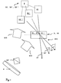
- the multiplex hologram 3 consists of a memory material with a plurality of interference patterns 31, 31 ', 31 ".
- the memory material is, for example, illuminated with an optical interference pattern 31, 31', 31" or printed with a digital interference pattern 31, 31 ', 31 " the provision of a multiplex hologram 3, such as the embossing of interference patterns 31, 31 ', 31 "in a memory material, etc. are also possible.
- FIG. 1 This is achieved by illuminating the memory material with an optical interference pattern 31, 31 ', 31 ".
- a coherent light source such as a helium neon laser, an argon laser, a neodymium laser diode, an arc or halogen lamp, etc. with a reference light wave
- the light source 4 generates a reference light wave 400 which is divided by a beam splitter 40.
- a part of the reference light wave 400 is directed to objects 41, 41 ', 41 "to be recorded, a part of the reference light wave 400 is directed to a light source 400 Hologram plane 30 of the multiplex hologram 3 steered.
- the reference light wave 400 is reflected by the objects 41, 41 ', 41 "and impinges on the hologram plane 30 as an object light wave 401 at an angle of incidence 32, 32', 32".
- the angle of incidence 32, 32 ', 32 " is the angle between the object light wave 401 and the normal of the hologram plane 30.
- the overlay of reference light wave 400 and object light wave 401 generates in the memory material a plurality of interference patterns 31, 31 ', 31 "as a function of the angles of incidence 32, 32', 32" of the object light wave 401 reflected at the objects 41, 41 ', 41 ".
- the number of interference patterns 31, 31 ', 31 "of the hologram plane 30 is limited by Bragg's equation
- Each object 41, 41', 41" is recorded at a unique angle of incidence 32, 32 ', 32 "
- the term “one-to-one” is used so that all angles of incidence 32, 32 ', 32 "differ from each other.
- the angular resolution increases with the thickness of the memory material. Therefore, so-called volume holograms are preferable in which a thickness of the storage material is larger than the wavelength of the light source 4.
- Digital printing patterns 31, 31 ', 31 are synthetically provided in a computer and written into the holographic storage material by a process similar to printing, but digital interference patterns 31, 31', 31" do not require physically real objects.
- Such multiplex holograms are inexpensive, the manufacturing costs are around 0.5 € per centimeter 2 .
- digital interference patterns 31, 31 ', 31 "and optical interference patterns 31, 31', 31” are equivalent.
- the interference patterns 31, 31 ', 31 "give an angle of incidence 32, 32 ', 32 "having at least one angular coordinate such as an azimuth angle coordinate ⁇ or a polar angle coordinate ⁇ .
- the interference patterns 31, 31', 31" can be provided at one or more wavelengths of the light source 4.
- interference patterns having a first wavelength may indicate the azimuth angle coordinate ⁇ of an angle of incidence
- interference patterns having a second wavelength different from the first one may indicate the polar angle coordinate ⁇ of this angle of incidence.
- the angular resolution of the multiplex hologram 3 is in the range of 0.1mrad to 1.0mrad, preferably 0.3mrad.
- the angular extent of the multiplex hologram 3 is 0.1 to nrad. With an angular resolution of 0.3 mrad and using, for example, 3333 identical interference patterns 31, 31 ', 31 ", the angle circumference is thus 1rad.
- At least one multiplex hologram 3 is arranged on the element 1.
- multiple multiplex holograms 3 can also be arranged on the first element 1, each of which covers a different angular range.
- a first multiplex hologram 3 covers an angular range of 0 to 1rad
- a second multiplex hologram 3 covers an angular range of 1 to 2rad
- a third multiplex hologram 3 covers an angular range of 2 to 3rad, etc.
- a corresponding incident angle 32, -32 ', 32 "of each object 41, 41', 41” is detected by an angle sensor 5.
- An angle signal 52, 52 ', 52 " is formed which comprises a pairing of the object 41, 41', 41” and its angles of incidence 32, 32 ', 32 ".
- the angle signal 52, 52', 52" can also contain further information such as Height and width of the bell curve Bragg intensity I of intensity patterns 61, 61 ', 61 ", etc.
- the angle signal 52, 52', 52" is computer-readable data stored.
- an information content of the object 41, 41 ', 41 "indicates the angle of incidence 32, 32', 32".
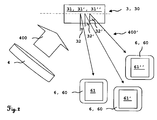
- FIG. 2 For this purpose, a multiplex hologram 3 with reference light wave 400 is illuminated, and a reference light wave 400 'diffracted by the interference pattern 31, 31', 31 "is output by a light detector 6 as an intensity pattern 61, 61 ', 61
- the reconstruction of the intensity pattern 61, 61 ', 61 "takes place as a function of the angle of incidence 32, 32', 32", ie the light detector 6 must be at the angle of incidence 32, 32 ', 32 "of an interference pattern 31, 31', 31 to the multiplex hologram 3 to detect an intensity pattern 61, 61 ', 61 ".
- the light source 4 can be operated continuously or pulsed. In a pulsed operation, a pulse width modulation can be carried out for the transmission of at least one additional information.
- the light source 4 transmits additional information such as the type of the multiplex hologram 3, the version of the interference patterns 31, 31 ', 31 ", an angle signal 52, 52', 52", an ambient temperature, etc. to the illumination of the multiplex hologram 3 with reference light wave 400 Light detector 6, which makes the process even clearer and more robust.
- the light source 4 advantageously has a broad band of wavelengths of light waves, of which the multiplex hologram 3 is at least one wavelength of a reference light wave 400 bends with high efficiency. For volume holograms, white light can be used.
- the light detector 6 has at least one sensor 60, 60 'such as a charge-coupled device (CCD) sensor or a complementary metal oxide semiconductor (CMOS) sensor.
- the light detector 6 detects the intensity pattern 61, 61 ', 61 "in a detector plane
- the light detector 6 detects at least the wavelength of the diffracted reference light source 400' and forms the intensity pattern 61, 61 ', 61".
- the light detector 6 may have filters to unambiguously form the intensity pattern 61, 61 ', 61 "using multiple wavelengths of the light source 4.
- the light detector 6 detects the diffracted reference light wave 400' based on the angular resolution given by Bragg's equation of the multiplex hologram 3 with different Bragg intensity I over a small angular range of the angle of incidence 32, 32 ', 32 ". That the light detector 6 can measure the detected Bragg intensity I within an angular range, for example, by summing up the detected photons per pixel of the sensor 60.
- the Bragg intensity I has approximately the shape of a bell curve, in the center of the angular range is the detected Bragg intensity I of the diffracted reference light wave 400 'maximum.
- FIGS. 3 to 6 show four exemplary embodiments of intensity patterns 61, 61 ', 61 ", which are largely identical to their underlying object 41, 41', 41". These are known opto-electronically readable bar codes.
- FIG. 3 Fig. 11 shows an intensity pattern 61, 61 ', 61 "in the embodiment of a two-dimensional codeclock F code having a plurality of lines of one-dimensional bar codes
- F-codes is standardized according to ISO / IEC 15417 of the International Organization for Standardization (ISO) and can have two to 44 lines.
- Each Codablock F-Code can be encoded up to 1Kbyte.
- FIG. 4 shows an intensity pattern 61, 61 ', 61 "in the embodiment of a two-dimensional DataMatrix code having a square or rectangular area as a pattern of square or round symbol elements.
- the DataMatrix code is normalized according to ISO / IEC 16022.
- Per DataMatrix code can be encoded more than 1Kbyte.
- FIG. 5 shows an intensity pattern 61, 61 ', 61 "in the embodiment of a two-dimensional maxi-code with hexagonal symbol elements and a central search pattern in the form of three concentric circles
- the search pattern is clearly visible and allows a clear centering of the light detector 6 and a correction of distortions in the detected
- the MaxiCode has a low information content of around 50 bytes, but the MaxiCode can be read very quickly and reliably thanks to the search pattern.
- FIG. 6 Figure 4 shows an intensity pattern 61, 61 ', 61 "in the embodiment of a two-dimensional quadratic symbol quadrature quick response code
- the Quick Response code is normalized according to the ISO / IEC 18004: 2006 standard and has synchronization marks in the corners of the matrix On, which allow a clear orientation of the intensity pattern, so that the beginning and end of the QuickResponse code are clearly detectable.
- the information content of the Quick Response code is very high and is just under 3KByte.
- intensity patterns not shown.
- symbol elements with eight, sixteen, and more different gray levels can be used, which further increases the information content of the intensity patterns.
- those skilled in the art can use intensity patterns with different sized symbol elements so that larger symbol elements of an intensity pattern can be clearly detected from a distance of several hundred meters, while smaller symbol elements of the intensity pattern can be clearly detected from a small distance of less than fifty meters.
- Fig. 7 1 shows a data communication between an angle sensor 5 with an evaluation unit 7 and / or between a light detector 6 and an evaluation unit 7.
- the angle sensor 5 transmits angle signals 52, 52 ', 52 "to the evaluation unit 7, and the light detector 6
- only the light detector 6 transmits intensity patterns 61, 61 ', 61 "to the evaluation unit 7.
- the instantaneous, in real time detected intensity patterns 61, 61', 61" are transmitted to the evaluation unit 7.
- the data communication is bidirectional and can be wired or wireless.
- Cable-based or radio-based data communication uses a protocol such as the Transmission Control Protocol / Internet Protocol (TCP / IP).
- Cable-based data communication takes place via a data bus such as Ethernet, USB, etc.
- Wireless data communication takes place via a radio network such as Enhanced Data Rate for GSM Evolution (EDGE), Asymetric Digital Subscriber Line (ADSL), Institute of Electrical and Electronics Engineers (IEEE) 802.11, etc.
- EDGE Enhanced Data Rate for GSM Evolution
- ADSL Asymetric Digital Subscriber Line
- IEEE Institute of Electrical and Electronics Engineers 802.11, etc.
- Both the angle sensor 5, the light detector 6 and the evaluation unit 7 have corresponding interfaces for data communication.
- the person skilled in the art can also execute the light detector with an evaluation unit integrated in the housing as a single unit.
- the evaluation unit 7 has a microprocessor and a computer-readable data memory.
- the computer program means is loaded from the computer-readable data memory of the evaluation unit 7 in the microprocessor of the evaluation unit 7 and executed.
- the evaluation unit 7 may be a stationary computer such as a personal computer (PC) or a mobile computer such as a laptop, smartphone, etc.
- the computer program means assigns to each transmitted intensity pattern 61, 61 ', 61 "a corresponding angle signal 52, 52', 52". For this purpose, the computer program means compares the bar code of an intensity pattern 61, 61 ', 61 "with those of the objects 41, 41', 41” in accordance with the angle signals 52, 52 ', 52 “. 61 ", the incident pattern 32, 32 ', 32" of the object 41, 41', 41 "according to angle signal 52, 52 ', 52" assigned.
- the computer program means reads out the information content of the two-dimensional bar code, which information content indicates the angle of incidence 32, 32 ', 32 ".
- the intensity pattern 61, 61', 61" this read-out angle of incidence 32, 32 ', 32 "is assigned.
- a multiplex hologram 3 is arranged on a first element 1 and the light detector 6 is arranged on a second element 2.
- the arbitrarily designed elements 1, 2 are spatially separated from each other, they may be less than a meter or several hundred meters apart.
- the multiplex hologram 3 is externally attached to the first element 1 or internally in the first element 1 such that the hologram plane 30 of the planar memory material is aligned in a known fixed spatial relationship to a first element plane 10 of the first element 1.
- the light detector 6 is externally attached to the second element 2 such that a detector plane of the light detector 6 is aligned in a known fixed spatial relationship to a second element plane 20 of the second element 2.
- the light detector 6 itself can also form the second element 2.
- a multiplex hologram 3 arranged on a first element 1 can be detected by a plurality of light detectors 6 arranged on second elements 2 such that an angle between the first element plane 10 and the second element plane 20 is calculated for each second element 2. This can be done independently of each other and with a time delay or at the same time.
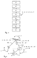
- FIG. 8 shows a flowchart of the method for measuring an angle between two spatially separated elements 1, 2, with the steps: a) providing a multiplex hologram 3 with a plurality of arranged in a hologram plane 30 interference patterns 31, 31 ', 31 ", at least two interference pattern 31, 31 ', 31 "have different angles of incidence 32, 32', 32" of an object light wave 401 the hologram plane 30, the angles of incidence 32, 32 ', 32 "of the interference patterns 31, 31', 31” are computer-readable data-stored; b) arranging the multiplex hologram 3 in a first element plane 10 on a first element 1; c) illuminating the multiplex hologram 3 with a reference light wave 400; d) arranging a light detector 6 in a second element plane 20 on a second element 2; e) detecting a reference light wave 400 diffracted at an interference pattern 31, 31 ', 31 "with the light detector 6; f) forming an intensity pattern 61, 61', 61
- FIGS. 9 to 12 show four exemplary embodiments of a system for carrying out the method.
- the system comprises the multiplex hologram 3, the light source 4, the light detector 6 and the evaluation device 7.
- the multiplex hologram 3 is arranged on the first element 1, the hologram plane 30 is congruent to the first element plane 10.
- the light detector 6 is arranged on the second element 2, the The detector plane is congruent with the second element plane 20.
- Coordinates of the second element plane 20 are indicated in a reference coordinate system K such as a polar coordinate system, a spherical coordinate system or an orthogonal coordinate system.
- An azimuth angle coordinate ⁇ and / or a polar angle coordinate ⁇ of the angle between the elements 1, 2 is measured.
- the reference coordinate system K may be a relative or absolute coordinate system.
- the intensity pattern 61, 61 ', 61 "becomes an angle of incidence
- the angle between the first element plane 10 and the second element plane 20 is calculated from the difference of the coordinates of the second element plane 20 and the coordinates of the associated angle of incidence 32, 32 ', 32 ". Coordinate ⁇ of the angle can be measured simultaneously.
- the person skilled in the art can arrange the multiplex hologram 3 at any known arrangement angle on the first element 1; the congruence of the hologram plane 30 to the first element level 10 is therefore not mandatory.
- the skilled person can arrange the light detector 6 at any known arrangement angle on the second element 2; also the congruence of the detector plane to the second element level 20 is not mandatory.
- the FIGS. 9 to 12 shows a multiplex hologram 3 in the embodiment of a reflection hologram that reflects the diffracted reference light wave 400 '.
- the multiplex hologram 3, the light source 4 and the light detector 6 form components of a system.
- placeable means any spatial placement of the component of the system in the reference coordinate system.
- alignable is understood to mean any orientation of the component of the system in the reference coordinate system. Specifically, however, always one of these components of the system is variably arranged and two of these components of the system are fixed and fixed Orientation arranged relative to each other. This is the basic embodiment of the invention. This spatially variable alignment and placement is limited by the angular extent of the multiplex hologram 3.
- the light detector 6 is spatially variably placeable and alignable, as shown by the arrow v.
- the light source 4 illuminates the multiplex hologram 3 at a constant reference light angle.
- the light source 4 and the laser detector 6 are mechanically connected to each other and fixedly arranged, which is represented by a designated f line. Only the multiplex hologram 3 is spatially variably placeable and alignable, as shown by the arrow v.
- the light source 4 illuminates the multiplex hologram 3 at a constant reference light angle
- the light detector 6 detects the diffracted reference light wave 400 'at a variable light detector angle, since the multiplex hologram 3 is spatially variably placeable and alignable.
- FIG. 12 shows a multiplex hologram 3 in the embodiment of a transmission hologram that transmits the diffracted reference light wave 400 '.
- the light detector 6 is arranged stationary, which is represented by a designated T-carrier.
- the light source 4 is mechanically connected to the multiplex hologram 3, which is represented by a line denoted by f.
- light source 4 and multiplex hologram 3 are spatially variably spatially placeable and alignable, as shown by the arrow v.
- the light source 4 illuminates the multiplex hologram 3 under a constant reference light angle.
- a diffracted reference light wave 400 'in the reference coordinate system K is detected by the light detector 6 in function of the azimuth angle coordinate ⁇ , and an intensity pattern 61 in the embodiment of a bar code is detected.
- Deviation of the spatial orientation of the two-dimensional bar code to the reference coordinate system K is measured as the roll angle ⁇ 'of the light detector 6.
- the roll angle is a tilting of the detector plane of the light detector 6 with respect to the second element plane 20.
- the roll angle ⁇ ' is another degree of freedom in measuring the angle between the two elements 1, 2nd
- a distortion of the intensity pattern 61, 61', 61 ' can be detected, for example, when an intensity pattern 61, 61', 61 'in the embodiment a MaxiCode after FIG. 5 an elliptically distorted search pattern, while the corresponding maxi-code of the object 41, 41 ', 41 "has a circular search pattern, and an angle between the first element 1 and the second element 2 can be measured very quickly from the magnitude and direction of such distortion
- the pattern may also be distorted differently, so the distortion may be square, trapezoidal, etc.
- FIGS. 14 to 17 10 show several embodiments of detecting a diffracted reference light wave 400 'with the light detector 6 and forming the intensity pattern 61, 61', 61 ".
- the light detector 6 may detect the detected Bragg intensity I within an angular range, for example by summing the detected photons per pixel of the sensor 60.
- the Bragg intensity I varies over the angular spacing of an intensity pattern 61, 61 ', 61 "and is approximately in the form of a bell curve, in the center of the angular range the detected Bragg intensity I of the diffracted reference light wave 400' is at most the height and width of the bell curve of FIG Bragg intensity I of the intensity patterns 61, 61 ', 61 "formed from the detected diffracted reference light wave 400' can be determined and thus beforehand known and computer-readable data stored.
- the variation of the detected Bragg intensity I with the detection angle can be used for a more accurate determination of the angular resolution of the intensity pattern 61, 61 ', 61 " diffracted reference light wave 400 'formed intensity pattern 61, 61', 61 "with a higher angular resolution than an angular distance of the intensity pattern 61, 61 ', 61" determined.
- the angle of incidence 32, 32 ', 32 can be assigned as a function of the height and width of the bell curve of the Bragg intensity I with a fine angular resolution to the intensity pattern 61, 61', 61". This fine angular resolution of the system can be increased by about a factor of ten.
- the intensity pattern 61, 61 ', 61 is computer-readable data storage.
- the intensity pattern 61 has a gray wedge 63, which is detected with different Bragg intensity I depending on the azimuth angle coordinate .theta.
- the light detector 6 measures the detected Bragg intensity I of the gray wedge 63 at different positions P in the intensity pattern 61 and compares the measured Bragg intensity I of the gray wedge 63 with a predefined threshold value 63 '.
- the position in the An intensity pattern in which the gray wedge 63 exceeds the threshold value 63 ' is proportional to the Bragg intensity I and thus provides information about the deviation of the angle from the angle with the maximum Bragg intensity I.
- a diffracted reference light wave 400 ' is detected in the reference coordinate system K in function of the azimuth angle coordinate ⁇ .
- the detected Bragg intensity I of the diffracted reference light wave 400 ' is variable, in the center of the angular range it is maximum, which is in the FIGS. 15 to 17 represented by an intensity curve.
- one of the detected diffracted reference lightwave 400 'intensity pattern 61 is the most intense, which is represented by a dark bar code at the center of the angle range, two bar codes outside the center are shown comparatively brighter.
- the multiplex hologram 3 detects an arrangement of interference patterns 31, 31 ', 31 " FIG. 1 on. For different azimuth angle coordinates ⁇ different intensity patterns 61, 61 'are detected. At maximum Bragg intensity I, only a single intensity pattern 61, 61 'is imaged. In the transition between two intensity patterns 61, 61 'of adjacent azimuth angle coordinates ⁇ , the Bragg intensity I of the diffracted reference light wave 400' is lower and two intensity patterns 61, 61 'are imaged.
- FIG. 17 detects a light detector 6 with two sensors 60, 60 ', the diffracted reference light wave 400'.
- the two sensors 60, 60 'of the light detector 6 are largely identical and are in a known fixed spatial intersensor distance to each other.
- the two sensors 60, 60 'in the inter-sensor distance of 1/3 of the angular range of the Bragg-intensive angular resolution of the multiplex hologram 3 are arranged to each other.
- the diffracted reference light wave 400 'intensity pattern 61 in the embodiment of a bar code is shown comparatively brighter in the center of the angular range at the most intense and out of the center.
- the difference in the determined brightness can be used to determine the angle with higher accuracy.
- the distance is greater than the angular range of the Bragg angular resolution.
- both detectors receive different intensity patterns corresponding to different angles with respect to the multiplex hologram 3.
- a distance between the first element 1 and the second element 2 can be easily calculated from the angle of incidence 32, 32 ', 32 "and the intersensor distance.
- the system can be combined with an existing device for electronic distance measurement (EDM), in which a distance between the first element 1 and the second element 2 is measured by transit time measurement or phase shift of electromagnetic or acoustic waves.
- EDM electronic distance measurement
- the accuracy of the EDM is at geodesic distances in the mm range.
- the changing spatial orientation of the mobile device's multiplex hologram 3 is detected by the second element 2 by illuminating the multiplex hologram 3 with reference light wave 400 'and the light detector 6 detects the reference light wave 400 diffracted at the interference pattern 31, 31', 31 "and an intensity pattern 61, 61 ', 61 ".
- the angle between the first element plane 10 and the second element plane 20 can be calculated.
- the multiplex hologram 3 of the probe device may be flat or curved. Multiple multiplex holograms 3, four, six, eight, ten, or more multiplex holograms 3 may be mounted on the stylus to facilitate illuminating a multiplex hologram 3 and detecting diffracted reference lightwave 400 'from as many different spatial orientations of the probe as possible.
- the multiplex hologram 3 can also be attached to other mobile three-dimensional measuring instruments such as Cognitens TM OptiGo, Cognitens TM OptiCell, Cognitens TM WLS400, etc.
- At least one multiplex hologram 3 is attached to a construction machine such as an excavator, a loader, a caterpillar, a grader, etc.
- the first element 1 is designed as a construction machine.
- the person skilled in the art can also attach the multiplex hologram 3 to a component of a construction machine, such as a joint, a tool, etc.
- At least one multiplex hologram 3 is fixedly attached to a static object such as a wall, a mast, a survey pole, and so on.
- the first element 1 is executed as a static object.
- a location determination of the second element 2 takes place by means of backward slicing.
- the second element 2 is a mobile measuring device such as a scanner, tracker, rotating laser, total station, etc.
- the multiplex hologram 3 of the static object may be planar or curved; Thus, it may include the circumference of an outer surface of a surveying rod in parts or completely.
- the multiplex hologram 3 of the static object can be used outdoors and indoors for both terrestrial surveying and airborne surveying.
- the multiplex hologram 3 can be indirectly targeted directly or via prisms to measure a hidden target point.
- a system with at least one multiplex hologram 3, a light source 4, a light detector 6 and an evaluation unit 7 is used as an angle encoder.
- the multiplex hologram 3 is attached to a first element 1 in the design of a dynamic object such as a joint, articulated arm, robotic arm, etc.
- the multiplex hologram 3 may be flat or curved.
- At least one multiplex hologram 3 is attached to a coordinate measuring machine.
- the first element 1 is designed as a coordinate measuring machine.
- At least one camera such as a single camera or a stereo camera, monitors the multiplex hologram 3.
- the camera corresponds to the second element 2.
- the changing spatial orientation of the multiplex hologram 3 of the probe device is detected by the second element 2 by illuminating the multiplex hologram 3 with reference light wave 400 'and the light detector 6 diffracting the interference pattern 31, 31', 31 " Reference light wave 400 'detected and formed an intensity pattern 61, 61', 61 ".
- the intensity pattern 61, 61 ', 61 is assigned an angle of incidence 32, 32', 32".
- the coordinate measuring machine can be monitored at short notice or in the long term. During a short-term monitoring of changing angles of incidence 32, 32 ', 32 "deformations in the operation of the coordinate measuring machine determined, so can be determined by the Detecting startup dynamics in real time and eliminate them. In the case of long-term monitoring, changing angles of incidence 32, 32 ', 32 "of material fatigue during operation of the coordinate measuring machine are determined.
- At least one multiplex hologram 3 is attached to a reference object of a coordinate measuring machine.
- the calibration object may be a reference element, a measuring table, etc.
- the first element 1 is designed as a calibration object.
- the spatial orientation of the multiplex hologram 3 is detected by the second element 2 by illuminating the multiplex hologram 3 with the reference light wave 400 'and the light detector 6 detects the reference light wave 400' diffracted at the interference patterns 31, 31 ', 31 "and an intensity pattern 61, 61 ', 61 "formed.
- the intensity pattern 61, 61 ', 61 is assigned at least one angle of incidence 32, 32', 32".
- the second element 2 is moved in a calibration position until the associated angle of incidence 32, 32 ', 32 "corresponds to a predefined calibration angle.
Landscapes
- Physics & Mathematics (AREA)
- General Physics & Mathematics (AREA)
- Engineering & Computer Science (AREA)
- Radar, Positioning & Navigation (AREA)
- Remote Sensing (AREA)
- Length Measuring Devices By Optical Means (AREA)
- Holo Graphy (AREA)
Claims (15)
- Procédé de mesure d'un angle entre deux éléments éloignés spatialement l'un de l'autre (1, 2) avec :• mise à disposition d'un hologramme multiplexe (3) avec plusieurs motifs d'interférence (31, 31',31") indépendants placés dans un plan d'hologramme (30), au moins deux motifs d'interférence (31, 31', 31") présentent différents angles d'incidence (32, 32', 32"') d'une onde de lumière d'objet (401) sur le plan de l'hologramme (30), les angles d'incidence (32, 32', 32"') sont mémorisés de manière lisible par ordinateur ;• placement de l'hologramme multiplexe (3) dans un premier plan d'élément (10) sur un premier élément (1) ;• éclairage de l'hologramme multiplexe (3) avec une onde de lumière de référence (400) ;• placement d'un détecteur de lumière (6) dans un second plan d'élément (20) sur un second élément (2) ;• détection d'une onde de lumière de référence diffractée (400') sur un motif d'interférence (31, 31', 31") avec le détecteur de lumière (6) ;• formation d'un motif d'intensité (61, 61', 61") à partir de l'onde de lumière de référence diffractée détectée (400') ;• assignation de l'angle d'incidence mémorisé de manière lisible par ordinateur (32, 32', 32") au motif d'intensité (61, 61', 61") et• calcul d'un angle entre le premier plan d'élément (10) et le second plan d'élément (20) à partir de l'angle d'incidence assigné (32, 32', 32").
- Procédé selon la revendication 1, caractérisé en ce que les différents angles d'incidence (32, 32', 32") sont soumis entre eux à une distribution discrète discontinue et un nombre discret de motifs d'interférence indépendants (31, 31', 31") qui peuvent être extraits individuellement est superposé dans une unité de l'hologramme multiplexe (3).
- Procédé selon la revendication 1 ou 2, caractérisé en ce qu'un motif d'intensité (61, 61', 61") est un arrangement étendu en surface d'une multitude de formes clairement différenciables du reste de la surface, cependant qu'un motif d'intensité (61, 61', 61") présente un contenu d'information lisible par machine, en particulier sous forme de code.
- Procédé selon l'une des revendications précédentes, caractérisé en ce que des coordonnées du second plan d'élément (20) sont indiquées dans un système de coordonnées de référence (K), que des coordonnées de l'angle d'incidence assigné (32, 32', 32") sont indiquées dans le système de coordonnées de référence (K) et qu'à l'étape h) l'angle est calculé à partir de la différence des coordonnées du second plan d'élément (20) et des coordonnées de l'angle d'incidence assigné (32, 32', 32").
- Procédé selon l'une des revendications précédentes, caractérisé en ce qu'un système de coordonnées de référence (K) avec une coordonnée d'angle d'azimut (θ) et une coordonnée d'angle polaire (ϕ) est utilisé et qu'à l'étape h) la coordonnée d'angle d'azimut (θ) et la coordonnée d'angle polaire (ϕ) de l'angle sont mesurées simultanément.
- Procédé selon l'une des revendications précédentes, caractérisé en ce qu'un signal d'angle (52, 52', 52"') qui présente l'angle d'incidence (32, 32', 32") et qui présente un objet (41, 41', 41") est mémorisé de manière lisible par ordinateur, qu'à l'étape g) le motif d'intensité (61, 61', 61") est comparé aux objets mémorisés de manière lisible par ordinateur (41, 41', 41") et que, lors de la concordance du motif d'intensité (61, 61', 61") avec un objet (41, 41', 41"), l'angle d'incidence (32, 32', 32") de cet objet (41, 41', 41") est associé au motif d'intensité (61, 61', 61").
- Procédé selon l'une des revendications précédentes, caractérisé en ce qu'à l'étape c) au moins l'une des informations supplémentaires suivantes :u n type d'hologramme multiplexe (3),u ne version des motifs d'interférence (31, 31', 31"),u n signal d'angle (52, 62', 52")est transmis par la source de lumière (4) au détecteur de lumière (6).
- Procédé selon l'une des revendications précédentes, caractérisé en ce qu'un code-barres bidimensionnnel est utilisé comme motif d'intensité (61, 61', 61"), en particulier cependant· qu'à l'étape g) un contenu d'information du code-barres bidimensionnel est extrait, lequel contenu d'information indique l'angle d'incidence (32, 32', 32") et que cet angle d'incidence extrait (32, 32', 32") est assigné au motif d'intensité (61, 61', 61") ou· qu'à l'étape e) une onde diffractée de lumière de référence (400') est détectée dans un système de coordonnées de référence (K) et une divergence d'une orientation spatiale du code-barres bidimensionnel par rapport au système de coordonnées de référence (K) est mesurée comme angle de roulis (ϕ') du détecteur de lumière (6).
- Procédé selon l'une des revendications précédentes, caractérisé en ce qu'à l'étape c) l'hologramme multiplexe (3) est éclairé avec l'onde de lumière de référence (400) selon un angle de lumière de référence constant et/ou qu'à l'étape c) l'hologramme multiplexe (3) est éclairé avec l'onde de lumière de référence (400) par une source de lumière de référence stationnaire (4) selon un angle de lumière de référence.constant.
- Procédé selon l'une des revendications précédentes, caractérisé en ce qu'à l'étape e) l'onde diffractée de lumière de référence (400') est détectée par un détecteur de lumière stationnaire (6) selon un angle de détecteur de lumière constant.
- Procédé selon l'une des revendications précédentes, caractérisé en ce qu'il est détecté une intensité de Bragg (I) de l'onde diffractée de lumière de référence détectée (400') et qu'en connaissant une variation de l'intensité de Bragg (I) en fonction de l'angle de détection, un angle du motif d'intensité (61, 61', 61") formé à partir de l'onde diffractée de lumière de référence détectée (400') est déterminé avec une résolution angulaire plus élevée qu'une distance angulaire des motif d'intensité (61, 61', 61").
- Procédé selon l'une des revendications précédentes, caractérisé en ce qu'un hologramme multiplexe (3) placé sur le premier élément (1) dans le premier plan d'élément (10) est détecté par plusieurs détecteurs de lumière (6) placés sur des seconds éléments (2) dans des seconds plans d'élément (20) et qu'un angle entre le premier plan d'élément (10) et le second plan d'élément (20) est mesuré à partir de l'angle d'incidence assigné (32, 32', 32") pour chaque second élément (2).
- Utilisation d'un hologramme multiplexe (3) pour exécuter le procédé selon l'une des revendications 1 à 12, cependant que le premier élément (1) est réalisé comme au moins l'un des dispositifs suivants :· un dispositif de palpage mobile,· une machine de chantier,· un objet statique,· un objet dynamique,· une machine de mesure de coordonnées,· un objet d'étalonnage d'une machine de mesure de coordonnées.
- Système qui est approprié pour exécuter le procédé selon l'une des revendications 1 à 12, caractérisé en cei) que le système présente un hologramme multiplexe (3) avec plusieurs motifs d'interférence indépendants (31, 31', 31") placés dans un plan d'hologramme (30),(ii) qu'au moins deux motifs d'interférence (31, 31', 31") de l'hologramme multiplexe (3) présentent deux angles d'incidence différents (32, 32', 32") d'une onde de lumière d'objet (401) sur le plan de l'hologramme (30), lesquels angles d'incidence (32, 32', 32") sont mémorisés de manière lisible par ordinateur,(iii) que l'hologramme multiplexe (3) est placé dans un premier plan d'élément (10) sur un premier élément (1),iv) que le système présente une source de lumière (4) qui éclaire l'hologramme multiplexe (3) avec une onde de lumière de référence (400),v) que le système présente un détecteur de lumière (6) qui est placé dans un second plan d'élément (20) sur un second élément (2), qui détecte une onde de lumière de référence (400') diffractée sur un motif d'interférence (31, 31', 31") et qui forme un motif d'intensité (61, 61', 61") à partir de l'onde de lumière de référence diffractée détectée (400') etvi) que le système présente une unité d'exploitation (7) qui assigne l'angle d'incidence mémorisé de manière lisible par ordinateur (32, 32', 32") au motif d'intensité (61, 61', 61") et qui calcule un angle entre le premier plan d'élément (10) et le second plan d'élément (20) à partir de l'angle d'incidence assigné (32, 32', 32").
- Produit de programme d'ordinateur comprenant un moyen de programme d'ordinateur qui est approprié pour mettre en oeuvre le procédé selon l'une des revendications 1 à 12 en ce qu'au moins l'une des étapes g) et h) est exécutée lorsque le moyen de programme d'ordinateur est chargé dans un microprocesseur d'une unité d'exploitation (7).
Priority Applications (1)
| Application Number | Priority Date | Filing Date | Title |
|---|---|---|---|
| EP13700318.2A EP2805131B1 (fr) | 2012-01-17 | 2013-01-16 | Procédé, appareil et produit de programme informatique de mesure d'un angle entre deux éléments éloignés l'un de l'autre et son utilisation |
Applications Claiming Priority (3)
| Application Number | Priority Date | Filing Date | Title |
|---|---|---|---|
| EP12151437.6A EP2618103A1 (fr) | 2012-01-17 | 2012-01-17 | Procédé, appareil et produit de programme informatique de mesure d'un angle entre deux éléments éloignés l'un de l'autre et son utilisation |
| PCT/EP2013/050761 WO2013107780A1 (fr) | 2012-01-17 | 2013-01-16 | Procédé destiné à mesurer un angle entre deux éléments situés à distance l'un de l'autre dans l'espace |
| EP13700318.2A EP2805131B1 (fr) | 2012-01-17 | 2013-01-16 | Procédé, appareil et produit de programme informatique de mesure d'un angle entre deux éléments éloignés l'un de l'autre et son utilisation |
Publications (2)
| Publication Number | Publication Date |
|---|---|
| EP2805131A1 EP2805131A1 (fr) | 2014-11-26 |
| EP2805131B1 true EP2805131B1 (fr) | 2016-08-24 |
Family
ID=47559506
Family Applications (2)
| Application Number | Title | Priority Date | Filing Date |
|---|---|---|---|
| EP12151437.6A Withdrawn EP2618103A1 (fr) | 2012-01-17 | 2012-01-17 | Procédé, appareil et produit de programme informatique de mesure d'un angle entre deux éléments éloignés l'un de l'autre et son utilisation |
| EP13700318.2A Active EP2805131B1 (fr) | 2012-01-17 | 2013-01-16 | Procédé, appareil et produit de programme informatique de mesure d'un angle entre deux éléments éloignés l'un de l'autre et son utilisation |
Family Applications Before (1)
| Application Number | Title | Priority Date | Filing Date |
|---|---|---|---|
| EP12151437.6A Withdrawn EP2618103A1 (fr) | 2012-01-17 | 2012-01-17 | Procédé, appareil et produit de programme informatique de mesure d'un angle entre deux éléments éloignés l'un de l'autre et son utilisation |
Country Status (4)
| Country | Link |
|---|---|
| US (1) | US9625255B2 (fr) |
| EP (2) | EP2618103A1 (fr) |
| CN (1) | CN104011500B (fr) |
| WO (1) | WO2013107780A1 (fr) |
Families Citing this family (8)
| Publication number | Priority date | Publication date | Assignee | Title |
|---|---|---|---|---|
| US10877210B2 (en) | 2016-07-15 | 2020-12-29 | Light Field Lab, Inc. | Energy propagation and transverse anderson localization with two-dimensional, light field and holographic relays |
| GB201614330D0 (en) | 2016-08-22 | 2016-10-05 | Univ Of Sussex The | Attitude determination system |
| US10135527B1 (en) | 2016-12-22 | 2018-11-20 | X Development Llc | Method of communication link acquisition using search pattern |
| CN112074782B (zh) | 2018-01-14 | 2024-09-24 | 光场实验室公司 | 用于渲染来自3d环境的数据的系统和方法 |
| CN112105975A (zh) | 2018-01-14 | 2020-12-18 | 光场实验室公司 | 用于能量中继器中使用有序结构进行横向能量局域化的系统和方法 |
| KR20200116943A (ko) | 2018-01-14 | 2020-10-13 | 라이트 필드 랩 인코포레이티드 | 홀로그래픽 및 회절 광학 인코딩 시스템 |
| EP3737991A4 (fr) | 2018-01-14 | 2021-11-17 | Light Field Lab, Inc. | Ensemble boîtier à champ d'énergie à quatre dimensions |
| CN111156924B (zh) * | 2020-01-20 | 2021-04-02 | 长春长光智欧科技有限公司 | 高陡度光学镜凸面计算全息透射检测系统 |
Family Cites Families (16)
| Publication number | Priority date | Publication date | Assignee | Title |
|---|---|---|---|---|
| US4227807A (en) * | 1978-04-28 | 1980-10-14 | The Boeing Company | Holographic angle sensor |
| JPS57100304A (en) * | 1980-12-16 | 1982-06-22 | Komatsu Ltd | Angle detector |
| CH676043A5 (fr) | 1983-12-30 | 1990-11-30 | Wild Leitz Ag | |
| JPS61165611A (ja) * | 1985-01-18 | 1986-07-26 | Matsushita Electric Ind Co Ltd | 変化角度測定装置 |
| JPH06229756A (ja) * | 1993-02-05 | 1994-08-19 | Olympus Optical Co Ltd | 測距装置 |
| US5936723A (en) * | 1996-08-15 | 1999-08-10 | Go Golf | Orientation dependent reflector |
| JP3940874B2 (ja) * | 1999-10-19 | 2007-07-04 | 富士ゼロックス株式会社 | 光検索方法、光再生方法、光検索再生装置および光記録方法 |
| GB0119603D0 (en) * | 2001-08-13 | 2005-04-06 | Bae Systems Plc | Improvements in or relating to detectors |
| JP4361503B2 (ja) * | 2005-02-21 | 2009-11-11 | アルプス電気株式会社 | ホログラフィー記録装置,再生装置及びその方法並びにホログラフィー媒体 |
| US7839547B2 (en) | 2006-03-08 | 2010-11-23 | Kabushiki Kaisha Toshiba | Optical fiber illumination device and inspection apparatus |
| JP4746449B2 (ja) | 2006-03-08 | 2011-08-10 | 株式会社東芝 | 紙葉類検査装置 |
| WO2009091896A1 (fr) * | 2008-01-15 | 2009-07-23 | Optical Alchemy, Inc. | Capteur de position angulaire pour la détection d'une attitude relative |
| FR2940442B1 (fr) * | 2008-12-18 | 2011-03-18 | Laboratoire Central Des Ponts Et Chaussees | Capteur et systeme d'imagerie pour la detection a distance d'un objet |
| JP2011164493A (ja) * | 2010-02-12 | 2011-08-25 | Nippon Hoso Kyokai <Nhk> | 角度多重ホログラム記録方法および装置 |
| CN102221328B (zh) * | 2011-06-08 | 2012-09-19 | 上海理工大学 | 一种基于导模共振结构设计的高分辨率角度测量方法 |
| CN102589440B (zh) | 2012-01-11 | 2014-11-05 | 西安交通大学 | 连续变角度数字全息干涉测量的方法 |
-
2012
- 2012-01-17 EP EP12151437.6A patent/EP2618103A1/fr not_active Withdrawn
-
2013
- 2013-01-16 US US14/372,726 patent/US9625255B2/en active Active
- 2013-01-16 EP EP13700318.2A patent/EP2805131B1/fr active Active
- 2013-01-16 CN CN201380004420.0A patent/CN104011500B/zh active Active
- 2013-01-16 WO PCT/EP2013/050761 patent/WO2013107780A1/fr not_active Ceased
Also Published As
| Publication number | Publication date |
|---|---|
| CN104011500B (zh) | 2017-03-08 |
| CN104011500A (zh) | 2014-08-27 |
| EP2618103A1 (fr) | 2013-07-24 |
| US9625255B2 (en) | 2017-04-18 |
| EP2805131A1 (fr) | 2014-11-26 |
| US20150002840A1 (en) | 2015-01-01 |
| WO2013107780A1 (fr) | 2013-07-25 |
Similar Documents
| Publication | Publication Date | Title |
|---|---|---|
| EP2805131B1 (fr) | Procédé, appareil et produit de programme informatique de mesure d'un angle entre deux éléments éloignés l'un de l'autre et son utilisation | |
| AT506110B1 (de) | Vorrichtung und verfahren zur erfassung von körpermassdaten und konturdaten | |
| DE69804128T2 (de) | Kontaktlose lage- und orientierungsmessung | |
| DE69511099T2 (de) | Höhe und Kontur eines Objektes | |
| DE69826753T2 (de) | Optischer Profilsensor | |
| DE19940217C2 (de) | Verfahren zur berührungslosen Messung der Veränderung der räumlichen Gestalt einer Meßprobe, insbesondere zur Messung der Längenänderung der einer äußeren Kraft unterliegenden Meßprobe und Vorrichtung zur Durchführung des Verfahrens | |
| EP3433574B1 (fr) | Dispositif pour mesurer un objet en 3 dimensions, procédé et programme informatique associés à déclenchement basé sur une image | |
| WO2010089139A1 (fr) | Dispositif de mesure pour mesurer des déformations d'objet pouvant subir une déformation élastique | |
| DE112009004742T5 (de) | Optisches Messinstrument und Verfahren zur dreidimensionalen Oberflächenprofilmessung | |
| DE102012217240A1 (de) | Vorrichtung zum messen einer dreidimensionalen form | |
| DE102019103519B4 (de) | Vorrichtung zum Bestimmen von dimensionalen und/oder geometrischen Eigenschaften eines Messobjekts | |
| DE102018004592A1 (de) | Messapparat für dreidimensionale Geometrie und Messverfahren für dreidimensionale Geometrie | |
| EP2019281B1 (fr) | Procédé destiné au fonctionnement d'un capteur en 3D | |
| EP2095068A1 (fr) | Dispositif et procédé d'augmentation de la précision de mesure de systèmes numériques à géométrie en 3d | |
| DE112015002961T5 (de) | Verfahren zur Herstellung einer Komponente und Herstellungsvorrichtung, die ein solches Verfahren verwendet, und Volumenmessverfahren | |
| EP2600173A1 (fr) | Procédé destiné au fonctionnement d'un scanner laser | |
| DE112014006640B4 (de) | Verfahren und Vorrichtung zum Kalibrieren einer Abbildungsoptik für messtechnische Anwendungen | |
| DE4408226C2 (de) | Meßeinrichtung zur prozeßgekoppelten Bestimmung der Rauheit technischer Oberflächen durch Auswertung di- oder polychromatischer Specklemuster | |
| DE102004003941A1 (de) | Bestimmung von Koordinaten eines Werkstücks | |
| WO2007006642A1 (fr) | Capteur optique de longueur et de vitesse | |
| EP2031348B1 (fr) | Procédé d'inspection de surfaces destinée à détecter des défauts de surface et/ou mesurer la topographie de surface | |
| DE3910855C2 (fr) | ||
| DE68918006T2 (de) | Deformationsmessverfahren und Vorrichtung mit Photoelementdetektoren. | |
| DE102017208485A1 (de) | Anordnung und Verfahren zur berührungslosen Entfernungsbestimmung nach Art des Lichtschnittverfahrens | |
| WO2016155720A1 (fr) | Système et procédé pour déterminer le déplacement relatif de deux corps l'un par rapport à l'autre |
Legal Events
| Date | Code | Title | Description |
|---|---|---|---|
| PUAI | Public reference made under article 153(3) epc to a published international application that has entered the european phase |
Free format text: ORIGINAL CODE: 0009012 |
|
| 17P | Request for examination filed |
Effective date: 20140513 |
|
| AK | Designated contracting states |
Kind code of ref document: A1 Designated state(s): AL AT BE BG CH CY CZ DE DK EE ES FI FR GB GR HR HU IE IS IT LI LT LU LV MC MK MT NL NO PL PT RO RS SE SI SK SM TR |
|
| RIN1 | Information on inventor provided before grant (corrected) |
Inventor name: PETTERSSON, BO Inventor name: PRZYGODDA, FRANK Inventor name: SIERCKS, KNUT |
|
| DAX | Request for extension of the european patent (deleted) | ||
| RIN1 | Information on inventor provided before grant (corrected) |
Inventor name: SIERCKS, KNUT Inventor name: PETTERSSON, BO Inventor name: PRZYGODDA, FRANK |
|
| REG | Reference to a national code |
Ref country code: DE Ref legal event code: R079 Ref document number: 502013004154 Country of ref document: DE Free format text: PREVIOUS MAIN CLASS: G01B0011260000 Ipc: G01B0009020000 |
|
| RIC1 | Information provided on ipc code assigned before grant |
Ipc: G03H 1/30 20060101ALI20150722BHEP Ipc: G01C 15/00 20060101ALI20150722BHEP Ipc: G01B 9/02 20060101AFI20150722BHEP Ipc: G01B 9/021 20060101ALI20150722BHEP Ipc: G03H 1/00 20060101ALI20150722BHEP Ipc: G01B 11/26 20060101ALI20150722BHEP |
|
| GRAP | Despatch of communication of intention to grant a patent |
Free format text: ORIGINAL CODE: EPIDOSNIGR1 |
|
| INTG | Intention to grant announced |
Effective date: 20150902 |
|
| GRAS | Grant fee paid |
Free format text: ORIGINAL CODE: EPIDOSNIGR3 |
|
| INTG | Intention to grant announced |
Effective date: 20160129 |
|
| GRAA | (expected) grant |
Free format text: ORIGINAL CODE: 0009210 |
|
| AK | Designated contracting states |
Kind code of ref document: B1 Designated state(s): AL AT BE BG CH CY CZ DE DK EE ES FI FR GB GR HR HU IE IS IT LI LT LU LV MC MK MT NL NO PL PT RO RS SE SI SK SM TR |
|
| REG | Reference to a national code |
Ref country code: GB Ref legal event code: FG4D Free format text: NOT ENGLISH |
|
| REG | Reference to a national code |
Ref country code: CH Ref legal event code: EP |
|
| REG | Reference to a national code |
Ref country code: AT Ref legal event code: REF Ref document number: 823507 Country of ref document: AT Kind code of ref document: T Effective date: 20160915 Ref country code: CH Ref legal event code: NV Representative=s name: KAMINSKI HARMANN PATENTANWAELTE AG, LI |
|
| REG | Reference to a national code |
Ref country code: IE Ref legal event code: FG4D Free format text: LANGUAGE OF EP DOCUMENT: GERMAN |
|
| REG | Reference to a national code |
Ref country code: DE Ref legal event code: R096 Ref document number: 502013004154 Country of ref document: DE |
|
| REG | Reference to a national code |
Ref country code: NL Ref legal event code: FP |
|
| REG | Reference to a national code |
Ref country code: SE Ref legal event code: TRGR |
|
| REG | Reference to a national code |
Ref country code: LT Ref legal event code: MG4D |
|
| REG | Reference to a national code |
Ref country code: FR Ref legal event code: PLFP Year of fee payment: 5 |
|
| PG25 | Lapsed in a contracting state [announced via postgrant information from national office to epo] |
Ref country code: NO Free format text: LAPSE BECAUSE OF FAILURE TO SUBMIT A TRANSLATION OF THE DESCRIPTION OR TO PAY THE FEE WITHIN THE PRESCRIBED TIME-LIMIT Effective date: 20161124 Ref country code: RS Free format text: LAPSE BECAUSE OF FAILURE TO SUBMIT A TRANSLATION OF THE DESCRIPTION OR TO PAY THE FEE WITHIN THE PRESCRIBED TIME-LIMIT Effective date: 20160824 Ref country code: LT Free format text: LAPSE BECAUSE OF FAILURE TO SUBMIT A TRANSLATION OF THE DESCRIPTION OR TO PAY THE FEE WITHIN THE PRESCRIBED TIME-LIMIT Effective date: 20160824 Ref country code: IT Free format text: LAPSE BECAUSE OF FAILURE TO SUBMIT A TRANSLATION OF THE DESCRIPTION OR TO PAY THE FEE WITHIN THE PRESCRIBED TIME-LIMIT Effective date: 20160824 Ref country code: HR Free format text: LAPSE BECAUSE OF FAILURE TO SUBMIT A TRANSLATION OF THE DESCRIPTION OR TO PAY THE FEE WITHIN THE PRESCRIBED TIME-LIMIT Effective date: 20160824 Ref country code: FI Free format text: LAPSE BECAUSE OF FAILURE TO SUBMIT A TRANSLATION OF THE DESCRIPTION OR TO PAY THE FEE WITHIN THE PRESCRIBED TIME-LIMIT Effective date: 20160824 |
|
| PG25 | Lapsed in a contracting state [announced via postgrant information from national office to epo] |
Ref country code: PT Free format text: LAPSE BECAUSE OF FAILURE TO SUBMIT A TRANSLATION OF THE DESCRIPTION OR TO PAY THE FEE WITHIN THE PRESCRIBED TIME-LIMIT Effective date: 20161226 Ref country code: ES Free format text: LAPSE BECAUSE OF FAILURE TO SUBMIT A TRANSLATION OF THE DESCRIPTION OR TO PAY THE FEE WITHIN THE PRESCRIBED TIME-LIMIT Effective date: 20160824 Ref country code: GR Free format text: LAPSE BECAUSE OF FAILURE TO SUBMIT A TRANSLATION OF THE DESCRIPTION OR TO PAY THE FEE WITHIN THE PRESCRIBED TIME-LIMIT Effective date: 20161125 Ref country code: LV Free format text: LAPSE BECAUSE OF FAILURE TO SUBMIT A TRANSLATION OF THE DESCRIPTION OR TO PAY THE FEE WITHIN THE PRESCRIBED TIME-LIMIT Effective date: 20160824 |
|
| PG25 | Lapsed in a contracting state [announced via postgrant information from national office to epo] |
Ref country code: RO Free format text: LAPSE BECAUSE OF FAILURE TO SUBMIT A TRANSLATION OF THE DESCRIPTION OR TO PAY THE FEE WITHIN THE PRESCRIBED TIME-LIMIT Effective date: 20160824 Ref country code: EE Free format text: LAPSE BECAUSE OF FAILURE TO SUBMIT A TRANSLATION OF THE DESCRIPTION OR TO PAY THE FEE WITHIN THE PRESCRIBED TIME-LIMIT Effective date: 20160824 |
|
| REG | Reference to a national code |
Ref country code: DE Ref legal event code: R097 Ref document number: 502013004154 Country of ref document: DE |
|
| PG25 | Lapsed in a contracting state [announced via postgrant information from national office to epo] |
Ref country code: SM Free format text: LAPSE BECAUSE OF FAILURE TO SUBMIT A TRANSLATION OF THE DESCRIPTION OR TO PAY THE FEE WITHIN THE PRESCRIBED TIME-LIMIT Effective date: 20160824 Ref country code: SK Free format text: LAPSE BECAUSE OF FAILURE TO SUBMIT A TRANSLATION OF THE DESCRIPTION OR TO PAY THE FEE WITHIN THE PRESCRIBED TIME-LIMIT Effective date: 20160824 Ref country code: CZ Free format text: LAPSE BECAUSE OF FAILURE TO SUBMIT A TRANSLATION OF THE DESCRIPTION OR TO PAY THE FEE WITHIN THE PRESCRIBED TIME-LIMIT Effective date: 20160824 Ref country code: DK Free format text: LAPSE BECAUSE OF FAILURE TO SUBMIT A TRANSLATION OF THE DESCRIPTION OR TO PAY THE FEE WITHIN THE PRESCRIBED TIME-LIMIT Effective date: 20160824 Ref country code: BE Free format text: LAPSE BECAUSE OF NON-PAYMENT OF DUE FEES Effective date: 20170131 Ref country code: BG Free format text: LAPSE BECAUSE OF FAILURE TO SUBMIT A TRANSLATION OF THE DESCRIPTION OR TO PAY THE FEE WITHIN THE PRESCRIBED TIME-LIMIT Effective date: 20161124 Ref country code: PL Free format text: LAPSE BECAUSE OF FAILURE TO SUBMIT A TRANSLATION OF THE DESCRIPTION OR TO PAY THE FEE WITHIN THE PRESCRIBED TIME-LIMIT Effective date: 20160824 |
|
| PLBE | No opposition filed within time limit |
Free format text: ORIGINAL CODE: 0009261 |
|
| STAA | Information on the status of an ep patent application or granted ep patent |
Free format text: STATUS: NO OPPOSITION FILED WITHIN TIME LIMIT |
|
| 26N | No opposition filed |
Effective date: 20170526 |
|
| PG25 | Lapsed in a contracting state [announced via postgrant information from national office to epo] |
Ref country code: SI Free format text: LAPSE BECAUSE OF FAILURE TO SUBMIT A TRANSLATION OF THE DESCRIPTION OR TO PAY THE FEE WITHIN THE PRESCRIBED TIME-LIMIT Effective date: 20160824 |
|
| PG25 | Lapsed in a contracting state [announced via postgrant information from national office to epo] |
Ref country code: MC Free format text: LAPSE BECAUSE OF FAILURE TO SUBMIT A TRANSLATION OF THE DESCRIPTION OR TO PAY THE FEE WITHIN THE PRESCRIBED TIME-LIMIT Effective date: 20160824 |
|
| REG | Reference to a national code |
Ref country code: IE Ref legal event code: MM4A |
|
| PG25 | Lapsed in a contracting state [announced via postgrant information from national office to epo] |
Ref country code: LU Free format text: LAPSE BECAUSE OF NON-PAYMENT OF DUE FEES Effective date: 20170116 |
|
| REG | Reference to a national code |
Ref country code: FR Ref legal event code: PLFP Year of fee payment: 6 |
|
| REG | Reference to a national code |
Ref country code: BE Ref legal event code: MM Effective date: 20170131 |
|
| PG25 | Lapsed in a contracting state [announced via postgrant information from national office to epo] |
Ref country code: IE Free format text: LAPSE BECAUSE OF NON-PAYMENT OF DUE FEES Effective date: 20170116 |
|
| PG25 | Lapsed in a contracting state [announced via postgrant information from national office to epo] |
Ref country code: MT Free format text: LAPSE BECAUSE OF FAILURE TO SUBMIT A TRANSLATION OF THE DESCRIPTION OR TO PAY THE FEE WITHIN THE PRESCRIBED TIME-LIMIT Effective date: 20160824 |
|
| PG25 | Lapsed in a contracting state [announced via postgrant information from national office to epo] |
Ref country code: AL Free format text: LAPSE BECAUSE OF FAILURE TO SUBMIT A TRANSLATION OF THE DESCRIPTION OR TO PAY THE FEE WITHIN THE PRESCRIBED TIME-LIMIT Effective date: 20160824 |
|
| REG | Reference to a national code |
Ref country code: AT Ref legal event code: MM01 Ref document number: 823507 Country of ref document: AT Kind code of ref document: T Effective date: 20180116 |
|
| PG25 | Lapsed in a contracting state [announced via postgrant information from national office to epo] |
Ref country code: AT Free format text: LAPSE BECAUSE OF NON-PAYMENT OF DUE FEES Effective date: 20180116 |
|
| PG25 | Lapsed in a contracting state [announced via postgrant information from national office to epo] |
Ref country code: HU Free format text: LAPSE BECAUSE OF FAILURE TO SUBMIT A TRANSLATION OF THE DESCRIPTION OR TO PAY THE FEE WITHIN THE PRESCRIBED TIME-LIMIT; INVALID AB INITIO Effective date: 20130116 |
|
| PG25 | Lapsed in a contracting state [announced via postgrant information from national office to epo] |
Ref country code: CY Free format text: LAPSE BECAUSE OF FAILURE TO SUBMIT A TRANSLATION OF THE DESCRIPTION OR TO PAY THE FEE WITHIN THE PRESCRIBED TIME-LIMIT Effective date: 20160824 |
|
| PG25 | Lapsed in a contracting state [announced via postgrant information from national office to epo] |
Ref country code: MK Free format text: LAPSE BECAUSE OF FAILURE TO SUBMIT A TRANSLATION OF THE DESCRIPTION OR TO PAY THE FEE WITHIN THE PRESCRIBED TIME-LIMIT Effective date: 20160824 |
|
| PG25 | Lapsed in a contracting state [announced via postgrant information from national office to epo] |
Ref country code: TR Free format text: LAPSE BECAUSE OF FAILURE TO SUBMIT A TRANSLATION OF THE DESCRIPTION OR TO PAY THE FEE WITHIN THE PRESCRIBED TIME-LIMIT Effective date: 20160824 |
|
| PGFP | Annual fee paid to national office [announced via postgrant information from national office to epo] |
Ref country code: SE Payment date: 20200121 Year of fee payment: 8 Ref country code: NL Payment date: 20200121 Year of fee payment: 8 |
|
| PGFP | Annual fee paid to national office [announced via postgrant information from national office to epo] |
Ref country code: CH Payment date: 20200121 Year of fee payment: 8 |
|
| PG25 | Lapsed in a contracting state [announced via postgrant information from national office to epo] |
Ref country code: IS Free format text: LAPSE BECAUSE OF FAILURE TO SUBMIT A TRANSLATION OF THE DESCRIPTION OR TO PAY THE FEE WITHIN THE PRESCRIBED TIME-LIMIT Effective date: 20161224 |
|
| REG | Reference to a national code |
Ref country code: CH Ref legal event code: PL Ref country code: SE Ref legal event code: EUG |
|
| REG | Reference to a national code |
Ref country code: NL Ref legal event code: MM Effective date: 20210201 |
|
| PG25 | Lapsed in a contracting state [announced via postgrant information from national office to epo] |
Ref country code: NL Free format text: LAPSE BECAUSE OF NON-PAYMENT OF DUE FEES Effective date: 20210201 |
|
| PG25 | Lapsed in a contracting state [announced via postgrant information from national office to epo] |
Ref country code: SE Free format text: LAPSE BECAUSE OF NON-PAYMENT OF DUE FEES Effective date: 20210117 Ref country code: LI Free format text: LAPSE BECAUSE OF NON-PAYMENT OF DUE FEES Effective date: 20210131 Ref country code: CH Free format text: LAPSE BECAUSE OF NON-PAYMENT OF DUE FEES Effective date: 20210131 |
|
| REG | Reference to a national code |
Ref country code: DE Ref legal event code: R081 Ref document number: 502013004154 Country of ref document: DE Owner name: HEXAGON INNOVATION HUB GMBH, CH Free format text: FORMER OWNER: HEXAGON TECHNOLOGY CENTER GMBH, HEERBRUGG, CH |
|
| REG | Reference to a national code |
Ref country code: GB Ref legal event code: 732E Free format text: REGISTERED BETWEEN 20260305 AND 20260311 |
|
| PGFP | Annual fee paid to national office [announced via postgrant information from national office to epo] |
Ref country code: GB Payment date: 20260123 Year of fee payment: 14 |
|
| PGFP | Annual fee paid to national office [announced via postgrant information from national office to epo] |
Ref country code: DE Payment date: 20260121 Year of fee payment: 14 |
|
| PGFP | Annual fee paid to national office [announced via postgrant information from national office to epo] |
Ref country code: FR Payment date: 20260123 Year of fee payment: 14 |