EP2805392B1 - Verbindungsverfahren, spannungsausgleichsnebenschaltung und spannungsausgleichsverbindungsrückführungsnetz in einer nichtleitenden architektur - Google Patents
Verbindungsverfahren, spannungsausgleichsnebenschaltung und spannungsausgleichsverbindungsrückführungsnetz in einer nichtleitenden architektur Download PDFInfo
- Publication number
- EP2805392B1 EP2805392B1 EP13704169.5A EP13704169A EP2805392B1 EP 2805392 B1 EP2805392 B1 EP 2805392B1 EP 13704169 A EP13704169 A EP 13704169A EP 2805392 B1 EP2805392 B1 EP 2805392B1
- Authority
- EP
- European Patent Office
- Prior art keywords
- cable
- connection
- equipotential
- sleeve
- network
- Prior art date
- Legal status (The legal status is an assumption and is not a legal conclusion. Google has not performed a legal analysis and makes no representation as to the accuracy of the status listed.)
- Active
Links
Images

Classifications
-
- H—ELECTRICITY
- H01—ELECTRIC ELEMENTS
- H01R—ELECTRICALLY-CONDUCTIVE CONNECTIONS; STRUCTURAL ASSOCIATIONS OF A PLURALITY OF MUTUALLY-INSULATED ELECTRICAL CONNECTING ELEMENTS; COUPLING DEVICES; CURRENT COLLECTORS
- H01R3/00—Electrically-conductive connections not otherwise provided for
-
- H—ELECTRICITY
- H02—GENERATION; CONVERSION OR DISTRIBUTION OF ELECTRIC POWER
- H02G—INSTALLATION OF ELECTRIC CABLES OR LINES, OR OF COMBINED OPTICAL AND ELECTRIC CABLES OR LINES
- H02G3/00—Installations of electric cables or lines or protective tubing therefor in or on buildings, equivalent structures or vehicles
- H02G3/02—Details
-
- H—ELECTRICITY
- H01—ELECTRIC ELEMENTS
- H01R—ELECTRICALLY-CONDUCTIVE CONNECTIONS; STRUCTURAL ASSOCIATIONS OF A PLURALITY OF MUTUALLY-INSULATED ELECTRICAL CONNECTING ELEMENTS; COUPLING DEVICES; CURRENT COLLECTORS
- H01R4/00—Electrically-conductive connections between two or more conductive members in direct contact, i.e. touching one another; Means for effecting or maintaining such contact; Electrically-conductive connections having two or more spaced connecting locations for conductors and using contact members penetrating insulation
- H01R4/10—Electrically-conductive connections between two or more conductive members in direct contact, i.e. touching one another; Means for effecting or maintaining such contact; Electrically-conductive connections having two or more spaced connecting locations for conductors and using contact members penetrating insulation effected solely by twisting, wrapping, bending, crimping, or other permanent deformation
- H01R4/18—Electrically-conductive connections between two or more conductive members in direct contact, i.e. touching one another; Means for effecting or maintaining such contact; Electrically-conductive connections having two or more spaced connecting locations for conductors and using contact members penetrating insulation effected solely by twisting, wrapping, bending, crimping, or other permanent deformation by crimping
- H01R4/20—Electrically-conductive connections between two or more conductive members in direct contact, i.e. touching one another; Means for effecting or maintaining such contact; Electrically-conductive connections having two or more spaced connecting locations for conductors and using contact members penetrating insulation effected solely by twisting, wrapping, bending, crimping, or other permanent deformation by crimping using a crimping sleeve
-
- B—PERFORMING OPERATIONS; TRANSPORTING
- B60—VEHICLES IN GENERAL
- B60R—VEHICLES, VEHICLE FITTINGS, OR VEHICLE PARTS, NOT OTHERWISE PROVIDED FOR
- B60R16/00—Electric or fluid circuits specially adapted for vehicles and not otherwise provided for; Arrangement of elements of electric or fluid circuits specially adapted for vehicles and not otherwise provided for
- B60R16/02—Electric or fluid circuits specially adapted for vehicles and not otherwise provided for; Arrangement of elements of electric or fluid circuits specially adapted for vehicles and not otherwise provided for electric constitutive elements
- B60R16/0207—Wire harnesses
- B60R16/0215—Protecting, fastening and routing means therefor
-
- H—ELECTRICITY
- H01—ELECTRIC ELEMENTS
- H01B—CABLES; CONDUCTORS; INSULATORS; SELECTION OF MATERIALS FOR THEIR CONDUCTIVE, INSULATING OR DIELECTRIC PROPERTIES
- H01B1/00—Conductors or conductive bodies characterised by the conductive materials; Selection of materials as conductors
- H01B1/02—Conductors or conductive bodies characterised by the conductive materials; Selection of materials as conductors mainly consisting of metals or alloys
- H01B1/023—Alloys based on aluminium
-
- H—ELECTRICITY
- H01—ELECTRIC ELEMENTS
- H01R—ELECTRICALLY-CONDUCTIVE CONNECTIONS; STRUCTURAL ASSOCIATIONS OF A PLURALITY OF MUTUALLY-INSULATED ELECTRICAL CONNECTING ELEMENTS; COUPLING DEVICES; CURRENT COLLECTORS
- H01R4/00—Electrically-conductive connections between two or more conductive members in direct contact, i.e. touching one another; Means for effecting or maintaining such contact; Electrically-conductive connections having two or more spaced connecting locations for conductors and using contact members penetrating insulation
- H01R4/58—Electrically-conductive connections between two or more conductive members in direct contact, i.e. touching one another; Means for effecting or maintaining such contact; Electrically-conductive connections having two or more spaced connecting locations for conductors and using contact members penetrating insulation characterised by the form or material of the contacting members
- H01R4/62—Connections between conductors of different materials; Connections between or with aluminium or steel-core aluminium conductors
-
- H—ELECTRICITY
- H01—ELECTRIC ELEMENTS
- H01R—ELECTRICALLY-CONDUCTIVE CONNECTIONS; STRUCTURAL ASSOCIATIONS OF A PLURALITY OF MUTUALLY-INSULATED ELECTRICAL CONNECTING ELEMENTS; COUPLING DEVICES; CURRENT COLLECTORS
- H01R43/00—Apparatus or processes specially adapted for manufacturing, assembling, maintaining, or repairing of line connectors or current collectors or for joining electric conductors
- H01R43/02—Apparatus or processes specially adapted for manufacturing, assembling, maintaining, or repairing of line connectors or current collectors or for joining electric conductors for soldered or welded connections
-
- H—ELECTRICITY
- H01—ELECTRIC ELEMENTS
- H01R—ELECTRICALLY-CONDUCTIVE CONNECTIONS; STRUCTURAL ASSOCIATIONS OF A PLURALITY OF MUTUALLY-INSULATED ELECTRICAL CONNECTING ELEMENTS; COUPLING DEVICES; CURRENT COLLECTORS
- H01R43/00—Apparatus or processes specially adapted for manufacturing, assembling, maintaining, or repairing of line connectors or current collectors or for joining electric conductors
- H01R43/04—Apparatus or processes specially adapted for manufacturing, assembling, maintaining, or repairing of line connectors or current collectors or for joining electric conductors for forming connections by deformation, e.g. crimping tool
- H01R43/048—Crimping apparatus or processes
-
- H—ELECTRICITY
- H01—ELECTRIC ELEMENTS
- H01R—ELECTRICALLY-CONDUCTIVE CONNECTIONS; STRUCTURAL ASSOCIATIONS OF A PLURALITY OF MUTUALLY-INSULATED ELECTRICAL CONNECTING ELEMENTS; COUPLING DEVICES; CURRENT COLLECTORS
- H01R43/00—Apparatus or processes specially adapted for manufacturing, assembling, maintaining, or repairing of line connectors or current collectors or for joining electric conductors
- H01R43/16—Apparatus or processes specially adapted for manufacturing, assembling, maintaining, or repairing of line connectors or current collectors or for joining electric conductors for manufacturing contact members, e.g. by punching and by bending
-
- H—ELECTRICITY
- H02—GENERATION; CONVERSION OR DISTRIBUTION OF ELECTRIC POWER
- H02G—INSTALLATION OF ELECTRIC CABLES OR LINES, OR OF COMBINED OPTICAL AND ELECTRIC CABLES OR LINES
- H02G3/00—Installations of electric cables or lines or protective tubing therefor in or on buildings, equivalent structures or vehicles
-
- Y—GENERAL TAGGING OF NEW TECHNOLOGICAL DEVELOPMENTS; GENERAL TAGGING OF CROSS-SECTIONAL TECHNOLOGIES SPANNING OVER SEVERAL SECTIONS OF THE IPC; TECHNICAL SUBJECTS COVERED BY FORMER USPC CROSS-REFERENCE ART COLLECTIONS [XRACs] AND DIGESTS
- Y10—TECHNICAL SUBJECTS COVERED BY FORMER USPC
- Y10T—TECHNICAL SUBJECTS COVERED BY FORMER US CLASSIFICATION
- Y10T29/00—Metal working
- Y10T29/49—Method of mechanical manufacture
- Y10T29/49002—Electrical device making
- Y10T29/49117—Conductor or circuit manufacturing
- Y10T29/49204—Contact or terminal manufacturing
- Y10T29/49208—Contact or terminal manufacturing by assembling plural parts
-
- Y—GENERAL TAGGING OF NEW TECHNOLOGICAL DEVELOPMENTS; GENERAL TAGGING OF CROSS-SECTIONAL TECHNOLOGIES SPANNING OVER SEVERAL SECTIONS OF THE IPC; TECHNICAL SUBJECTS COVERED BY FORMER USPC CROSS-REFERENCE ART COLLECTIONS [XRACs] AND DIGESTS
- Y10—TECHNICAL SUBJECTS COVERED BY FORMER USPC
- Y10T—TECHNICAL SUBJECTS COVERED BY FORMER US CLASSIFICATION
- Y10T29/00—Metal working
- Y10T29/49—Method of mechanical manufacture
- Y10T29/49002—Electrical device making
- Y10T29/49117—Conductor or circuit manufacturing
- Y10T29/49204—Contact or terminal manufacturing
- Y10T29/49208—Contact or terminal manufacturing by assembling plural parts
- Y10T29/49218—Contact or terminal manufacturing by assembling plural parts with deforming
Definitions
- the invention relates to a connection method equipotential bonding of a current return electrical wiring network in an architecture, in particular an aircraft fuselage, a wagon, a building or a motor vehicle.
- the invention applies in particular to the electrical networks of new-generation aircraft skin consisting of a composite material.
- the invention also relates to an equipotential shunt connection and to a current return network comprising such equipotential shunt connectors for implementing said method in a non-conductive architecture.
- the composite material of this new generation of skin comprises a heterogeneous material based on carbon fibers.
- the mesh functions of the electrical wiring were carried out by the aluminum skin of the old generation, in particular: the current return of the consumer equipment, the setting at the same potential of all the metal parts, the EMC protection (Electromagnetic Compatibility ) of the electrical installation, the flows of lightning currents - indirect and induced - as well as electrostatic charges.
- the invention thus aims to apply to any structure where the passage of electricity requires the preservation of at least some of these interconnection functions when the envelope of the structure or architecture is not conductive.
- Composite carbon materials are poor conductors of electricity and poorly support the heating caused by the Joule effect. Such a coating can not therefore be used to perform the above functions.
- Any conductor intended to realize an equipotential bonding should possess the following fundamental properties: to be an excellent conductor of the electricity (or, in other words, to ensure an extremely low resistivity performance), to have a low density in order to minimize the mass , remain imperatively economic in terms of cost, and meet other technical performance (service life, environmental performance, etc.).
- Aluminum is the material that best meets all of these criteria.
- the equipotential bonds are therefore generally made from sections of large or large aluminum section cable, that is to say of greater section than that of the so-called "AWG 10" gauge - that is greater than about 5 mm 2 - selected from the series dedicated to the aeronautical field.
- equipotential bonds are formed by this type of cable 201 by connecting for example the carrier carriers 111 to the central support 113 of the upper return network on the one hand and to the metal cross members 141 of the median return network on the other hand.
- the return network supports 113 or 141 no less than seven equivalent electrical resistances are crossed: the two resistances of the interfaces between the metal supports 111 and 113 or 141 and the fixing lugs 202, the two electrical resistances of the lug body 202, the two interface resistors between the lugs 202 and the cables 201 as well as the linear electrical resistance of the cable section 201 of large section.
- the lugs can be replaced by unipolar connectors having a movable part and a fixed part.
- two cable sections are connected directly to each other by stacking two lugs using a dowel or a terminal strip.
- connection of these equipments to the networks of return of current is carried out closer to these equipments due, in particular, of the need to control the voltage drops online.
- Such connections are generally made by rigid or flexible metal intermediate supports depending on the intensity of the forces to be transmitted simultaneously. These links then induce additional parasitic resistances.
- On these supports are fixed the connecting lugs to each portion of cable connected to an upper 110 and intermediate 120 return network and to the equipment concerned. This intermediate support introduces additional equivalent electrical resistances into the overall network, namely between the return networks and between each return network and said equipment.
- a triple junction with dowels or terminal strips is also possible instead of the intermediate support.
- Each stud or bar generates two equivalent electrical resistors interface between the pods.
- the invention aims to overcome the disadvantages of known connector means by simplifying the interconnections while preserving performance.
- the invention aims to achieve equipotential bonds between parts of the electrically efficient return network in terms of low resistivity, with for example an overall equivalent resistance of the order of a few milliohms.
- the invention preserves the interconnection functions defined throughout the lifetime of the aircraft, while the multiplication of the cable sections degrades the predictive reliability of the global current return network.
- the approach followed by the invention is to give the cable of large aluminum section an equipotential bonding type function, this connection being electrically connected by direct contact to as many equipment that it is physically possible to connect.
- the subject of the present invention is an equipotential bonding method of a current return network according to the features of claim 1, and a current return network according to the characteristics of claim 6 such that that used in claim 1.
- the invention also relates to an in-line equipotential shunt connection between a high-section aluminum alloy cable serving as an equipotential bonding of primary current return networks of a non-conductive architecture, and an equipment this architecture.
- This branch connection comprises a substantially cylindrical metal sleeve of the cable assembly by a securing means and a fixing means extending the sleeve to be fixed to a support of the equipment.
- the assembly sleeve is comprised of two end portions each housing a seal and surrounding a central area of electrical contact with the previously stripped cable in a window formed within the central area.
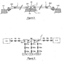
- an equipotential bonding connection is in the form of a cable 1, 35mm section 2 for example, based on aluminum.
- this cable 1 serves as equipotential bonding between the median network return 120 and the upper network return 110 presented in FIG. figure 1 at.
- the cable 1 and the metal supports 113 and 141, respectively of the upper networks 110 and median 120, are connected by the lugs 202.
- a device close to the link 1 and connected to the luggage rack 111 is electrically interconnected to this connection by an equipotential shunt connection in line 2 - hereinafter "shunt connection" - intermediate between the two ends of the cable
- the connection of derivation 2 comprises in the example a central cylindrical sleeve 2m and a tab 2p fixed to the support 111 by a screw 20.
- the cable is not interrupted, only three resistors are involved in this coupling: the interface resistance between the cable 1 and the bypass fitting 2, the body resistance of the branch fitting 2 and the resistance of the interface between the branch fitting 2 and the carrier 111.
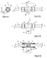
- the branch connection 2 comprises a central zone 21 extended at each end by a sealing zone 22, these zones forming the cylindrical sleeve 2m (cf. figure 2 ).
- the central zone 21 is extended transversely by the fixing lug 2p having a fixing hole 2t (traversed by the fixing screw 20 of the figure 2 ).
- the cross-sectional view of the figure 4c according to the plane CC shows the presence of notches 23 formed in at least one of the end zones 22. These notches allow for the radial angular orientation of the branch connection 2 with respect to the cable 1 according to the indications. of the template indicated on the cable.
- the sectional view of the figure 4d shows the result of the preparation of the cable 1 along its axis X'X.
- This preparation consists in stripping on a window of its core 11 by the elimination of its insulating sheath 12 in a crimping zone 21 s centered in the zone 21.
- the view 4d also shows the cylindrical seals 25 arranged in the In addition, it appears that the fixing lug 2p is axially substantially aligned along the axis X'X with the bare core window 11.
- This crimping is then performed in the electric crimping zone 21s located in the central zone 21.
- This crimping is of the "deep crimping" type achieved by similarity with crimping for the aluminum lugs, by adapting punches and dies to the geometry of the crimping. branch connection.
- a protective metal layer 27 anticorrosion is deposited on the inner wall of the branch connection 2 at the central crimping zone 21. This protection provides excellent electrical contact between the stripped core 11 and the inner wall of the coupler.
- the sealing zones 22 which enclose the seals 25 are crimped on the insulating sheath 12 of the cable 1 with a tooling of the same type as that used for the aluminum lugs.
- the sealing performance is equivalent, similar in size, to those required for the pods.
- conductive grease instead of surface treatments, for example for aluminum core cables without metal surface protection.
- cores consist of aluminum strands, jacketed for example with copper and nickel-plated.
- the bare core 11 is precoated with a thin layer of conductive grease electricity.
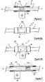
- the in-line shunt lug 2 ' is shaped so as to present a peripheral recess 3.
- the volume of the recess is predetermined so that it can largely receive all the volume of fat potentially possible.
- This recess allows the seal 25, arranged near the electric crimping zone 21s and inserted into its housing, not to be crimped on the grease. For this purpose, after orientation of the coupler by the notches (cf. figure 4c ), the crimps are then made.
- another embodiment consists in providing a fat injection channel.
- a cylindrical channel 4 passes through the branch connection 2 "in the central zone 21s, perpendicularly to its longitudinal axis X'X (coinciding with that of the cable 1), alternatively, the channel may be of inclined axis. a diameter sufficient to rapidly inject the amount of grease required and to allow - after orientation of the branch connection according to the template specifications and crimping of the central zone 21s - the closure of this channel by the movement of material caused by this crimping This closure guarantees the tightness of the crimping zone 21 s.
- the invention is not limited to the embodiments described and shown.
- the dimensions of the branch connection are adaptable according to the gauge and the insulating sheath of the cables.
- the surface treatment of the inner wall of the bypass connections is also adaptable by nickel plating, tinning, etc.
- all the techniques connection between the branch connection and the structure, which make it possible to make both an electrical connection and a mechanical connection, through suitable assemblies (multiple, vertical or partition fasteners) can be used: screwing, riveting, brazing , welding, hooping, etc.
- conductive or non-conductive compounds may also replace metal surface treatments or replace side seals.
- the injection channel or the recovery recess can be replaced by any other reserve or injection means.
Landscapes
- Engineering & Computer Science (AREA)
- Manufacturing & Machinery (AREA)
- Architecture (AREA)
- Civil Engineering (AREA)
- Structural Engineering (AREA)
- Mechanical Engineering (AREA)
- Connections Effected By Soldering, Adhesion, Or Permanent Deformation (AREA)
- Installation Of Indoor Wiring (AREA)
- Cable Accessories (AREA)
Claims (13)
- Verfahren zur Verbindung mit einer Äquipotentialverbindung eines Netzes zur Stromrückführung in einem Flugzeug, wobei das Netz primäre, longitudinale Netze zur Rückführung von Strom mit Bezug auf einen Flugzeugrumpf (110, 120, 130) umfasst, die örtlich weit voneinander entfernt sind, wobei eines von ihnen (110) zumindest aus Elementen (111, 112, 113) gebildet ist, die transversal beabstandet sind, so dass Äquipotentialverbindungen die primären Netze verbinden, um insgesamt ein Netz zur Rückführung von Strom zu bilden, dadurch gekennzeichnet, dass die Verbindungen aus einer Aluminiumverkabelung (1) mit einem großen Querschnitt bestehen, die aus einem einzigen Halter eine Äquipotentialverbindung zwischen den primären Netzen (110, 120, 130) sowie zwischen ihren Elementen (111, 112, 113) bildet, die transversal beabstandet sind, wobei die Einrichtungen möglichst nah bei ihrer Lage durch direkte, sukzessive Zwischenverbindungen (2, 2', 2", 2"') mit der Äquipotentialverbindung ohne Unterbrechung der Verkabelung verbunden sind, die durch eine elektrische und mechanische, gecrimpte Anordnung realisiert sind, wobei jede Zwischenverbindung zwei dichte Bereiche (22) aufweist, die einen zentralen Kontaktbereich (21) 'mit einer Abisolierung in einem Fenster (11) umgeben.
- Verfahren zur Verbindung nach Anspruch 1, wobei die Anordnungen an dem Kabel von jeder Verbindung (2, 2', 2", 2"') durch Techniken der Befestigung ausgeführt werden, die unter Schrauben, Nieten, Löten, Schweißen, Crimpen und Schrumpfen ausgewählt sind.
- Verfahren zur Verbindung nach einem der vorhergehenden Ansprüche, wobei ein leitfähiges Material auf die Abisolierung der Ummantelung (11) vor der Anordnung von jeder Zwischenverbindung (2, 2', 2", 2"') angewandt wird.
- Verfahren zur Verbindung nach einem der Ansprüche 1 oder 2, wobei eine Behandlung der Metalloberfläche (27) angewandt wird, um den elektrischen Kontakt zu verbessern und die Oxidation zu verhindern.
- Verfahren zur Verbindung nach einem der vorhergehenden Ansprüche, wobei jede Verbindung einen Bereich der elektrischen Anordnung (21 s) aufweist, der versetzt mit Bezug auf einen Befestigungsbereich (2p) der Zwischenverbindung (2, 2', 2", 2"') ist.
- Netz zur Rückführung von Strom in einem Flugzeug, das primäre, longitudinale Netze zur Stromrückführung mit Bezug auf einen Flugzeugrumpf (110, 120, 130) umfasst, die örtlich weit voneinander entfernt sind, wobei eines von ihnen (110) aus Elementen (111, 112, 113) gebildet ist, die transversal beabstandet sind, so dass Äquipotentialverbindungen die primären Netze verbinden, um insgesamt ein Netz zur Rückführung von Strom zu bilden, dadurch gekennzeichnet, dass die Verbindungen aus einer Aluminiumverkabelung (1) mit einem großen Querschnitt bestehen, die aus einem einzigen Halter eine Äquipotentialverbindung zwischen den primären Netzen (110, 120, 130) sowie zwischen ihren Elementen (111, 112, 113) bildet, die transversal beabstandet sind, wobei die Einrichtungen möglichst nah bei ihrer Lage durch Verbindungen der Äquipotentialabzweigung (2, 2', 2", 2"') mit dem Kabel (1) in Serie verbunden sind, die eine metallische, im Wesentlichen zylindrische Muffe (2m) zur Anordnung an dem Kabel (1) durch eine Verbindung und ein Mittel zur Befestigung (2p) umfasst, welches die Muffe (2m) verlängert, um sich mit einer Halterung (111) der Einrichtung verbinden zu lassen, wobei sich die Muffe zur Anordnung (2m) aus zwei Endabschnitten (22) zusammensetzt, die jeweils eine Dichtungsfuge (25) beherbergen und einen zentralen, elektrischen Kontaktbereich (21) mit dem Kabel (1) umgeben, das vorher in einem Fenster (11) abisoliert wurde, das im Inneren des zentralen Kontaktbereichs (21) ausgebildet ist.
- Netz nach dem vorangehenden Anspruch, wobei die Befestigung ein Crimpen durch einen Stempel und eine Matrize ist.
- Netz nach einem der Ansprüche 6 oder 7, wobei die Endabschnitte (22) auf einer isolierenden Ummantelung (12) des Kabels (1) mit einem Werkzeug der Art gecrimpt sind, das für Aluminiumhülsen vorgesehen ist.
- Netz nach einem der Ansprüche 6 bis 8, wobei die Muffe (2m) eine Innenwand besitzt, die mit einer metallischen, antikorrosiven Schutzschicht (27) bedeckt ist.
- Netz nach einem der Ansprüche 6 bis 8, wobei die innere Oberfläche der Muffe (2m) und der abisolierte Kern (11) des Kabels (1) Behandlungen der metallischen Oberflächen aufweisen.
- Netz nach einem der Ansprüche 6 bis 8, wobei der abisolierte Kern (11) des Kabels mit einer Schicht aus leitfähigem Fett bestrichen ist.
- Netz nach dem der vorhergehenden Anspruch, wobei eine Ausnehmung (3) zwischen der Muffe (2m) und dem Kabel (1), und zwischen dem abisolierten Fenster (11) des Kabels (1) und mindestens einer Fuge (25) eines Endabschnitts (22) der Muffe (2m) ausgebildet ist, so dass ein Überschuss an Fett, der beim Crimpen gebildet wird, gesammelt wird, ohne das Fett zwischen der Fuge (25) und dem Kabel (1) einzusperren.
- Netz nach Anspruch 11, wobei ein Kanal (4) durch die Muffe (2m) zum Injizieren der Menge an leitfähigem Fett so ausgebildet ist, dass sein Ende in dem elektrischen Crimpbereich (21 s) zwischen dem abisolierten Fenster (11) des Kabels (1) und der Innenfläche der Muffe (2 m) mündet, wobei das Crimpen geeignet ist, den Kanal (4) später nach der Orientierung der Muffe mit Hilfe von Ausnehmungen (23) abzudichten.
Applications Claiming Priority (2)
| Application Number | Priority Date | Filing Date | Title |
|---|---|---|---|
| FR1250597A FR2986114B1 (fr) | 2012-01-20 | 2012-01-20 | Procede de raccordement, raccord de derivation equipotentiel et reseau de retour courant a liaison equipotentielle dans une architecture non conductrice |
| PCT/FR2013/050104 WO2013107986A2 (fr) | 2012-01-20 | 2013-01-17 | Procédé de raccordement, raccord de dérivation équipotentiel et réseau de retour courant à liaison équipotentielle dans une architecture non conductrice |
Publications (2)
| Publication Number | Publication Date |
|---|---|
| EP2805392A2 EP2805392A2 (de) | 2014-11-26 |
| EP2805392B1 true EP2805392B1 (de) | 2016-05-18 |
Family
ID=47714408
Family Applications (1)
| Application Number | Title | Priority Date | Filing Date |
|---|---|---|---|
| EP13704169.5A Active EP2805392B1 (de) | 2012-01-20 | 2013-01-17 | Verbindungsverfahren, spannungsausgleichsnebenschaltung und spannungsausgleichsverbindungsrückführungsnetz in einer nichtleitenden architektur |
Country Status (9)
| Country | Link |
|---|---|
| US (1) | US20140354043A1 (de) |
| EP (1) | EP2805392B1 (de) |
| JP (1) | JP6118823B2 (de) |
| CN (1) | CN104247186B (de) |
| BR (1) | BR112014017551B1 (de) |
| CA (1) | CA2861256C (de) |
| FR (1) | FR2986114B1 (de) |
| RU (1) | RU2608754C2 (de) |
| WO (1) | WO2013107986A2 (de) |
Families Citing this family (7)
| Publication number | Priority date | Publication date | Assignee | Title |
|---|---|---|---|---|
| CN104218333B (zh) * | 2014-08-18 | 2016-03-30 | 中国运载火箭技术研究院 | 一种碳纤维复合材料飞行器等电位结构 |
| CN110679042B (zh) * | 2017-08-02 | 2023-01-17 | 阿维科斯公司 | 将第一电线与第二电线连接的设备和方法 |
| EP3490069B1 (de) * | 2017-11-23 | 2020-07-15 | A.E.C. S.r.l. | Leistungsanschluss |
| DE102019200094A1 (de) * | 2019-01-07 | 2020-07-09 | Volkswagen Aktiengesellschaft | Anordnung zur elektrischen Anbindung eines Massekabels an einen Minus-Pol einer Batterie |
| CN110011157B (zh) * | 2019-04-12 | 2024-07-16 | 吉林省长春电力勘测设计院有限公司 | 一种钢芯铝绞导线接续管压接工具 |
| CN114628853A (zh) * | 2022-03-15 | 2022-06-14 | 江铃汽车股份有限公司 | 一种等电位连接装置、使用方法以及电池包 |
| CN115189196A (zh) * | 2022-08-11 | 2022-10-14 | 安波福电气系统有限公司 | 汽车充电线束 |
Family Cites Families (7)
| Publication number | Priority date | Publication date | Assignee | Title |
|---|---|---|---|---|
| US4976627A (en) * | 1989-03-31 | 1990-12-11 | Thomas & Betts Corporation | Grid/ground connector |
| DE19937510A1 (de) * | 1999-08-09 | 2001-08-30 | Vw Bordnetze Gmbh Heinenkamp | Abgriff für ein Elektrokabel |
| FR2877774B1 (fr) * | 2004-11-08 | 2010-11-05 | Airbus France | Ensemble connecteur pour aeronef |
| US7241185B1 (en) * | 2005-12-22 | 2007-07-10 | Tensolite Company | Integral bonding attachment |
| US7896712B2 (en) * | 2005-12-22 | 2011-03-01 | Tensolite, Llc | Integral bonding attachment |
| FR2914622B1 (fr) * | 2007-04-04 | 2009-05-15 | Airbus France Sas | Aeronef comprenant une structure assurant les fonctions structurale et electrique |
| FR2941919B1 (fr) * | 2009-02-11 | 2011-04-08 | Airbus France | Element de reseau de retour de courant pour aeronef |
-
2012
- 2012-01-20 FR FR1250597A patent/FR2986114B1/fr not_active Expired - Fee Related
-
2013
- 2013-01-17 CN CN201380008242.9A patent/CN104247186B/zh active Active
- 2013-01-17 US US14/372,802 patent/US20140354043A1/en not_active Abandoned
- 2013-01-17 JP JP2014552679A patent/JP6118823B2/ja not_active Expired - Fee Related
- 2013-01-17 WO PCT/FR2013/050104 patent/WO2013107986A2/fr not_active Ceased
- 2013-01-17 CA CA2861256A patent/CA2861256C/fr not_active Expired - Fee Related
- 2013-01-17 EP EP13704169.5A patent/EP2805392B1/de active Active
- 2013-01-17 BR BR112014017551-9A patent/BR112014017551B1/pt not_active IP Right Cessation
- 2013-01-17 RU RU2014132554A patent/RU2608754C2/ru active
Non-Patent Citations (1)
| Title |
|---|
| None * |
Also Published As
| Publication number | Publication date |
|---|---|
| FR2986114B1 (fr) | 2015-02-27 |
| WO2013107986A3 (fr) | 2014-03-20 |
| US20140354043A1 (en) | 2014-12-04 |
| CA2861256C (fr) | 2019-01-15 |
| CA2861256A1 (fr) | 2013-07-25 |
| JP6118823B2 (ja) | 2017-04-19 |
| BR112014017551B1 (pt) | 2021-03-02 |
| EP2805392A2 (de) | 2014-11-26 |
| WO2013107986A2 (fr) | 2013-07-25 |
| CN104247186B (zh) | 2017-04-26 |
| RU2014132554A (ru) | 2016-03-20 |
| CN104247186A (zh) | 2014-12-24 |
| JP2015510663A (ja) | 2015-04-09 |
| RU2608754C2 (ru) | 2017-01-24 |
| BR112014017551A2 (pt) | 2017-07-04 |
| FR2986114A1 (fr) | 2013-07-26 |
Similar Documents
| Publication | Publication Date | Title |
|---|---|---|
| EP2805392B1 (de) | Verbindungsverfahren, spannungsausgleichsnebenschaltung und spannungsausgleichsverbindungsrückführungsnetz in einer nichtleitenden architektur | |
| EP2842208B1 (de) | Verbindungskabelstrang für stromrückfluss und verfahren zur montage auf einem zusammengesetzten rumpfgerüst | |
| US8246390B2 (en) | Integral bonding attachment | |
| JP2016503559A (ja) | 遮蔽されたワイヤケーブルをスプライス接続する(splicing)ための装置および方法 | |
| CN115803977B (zh) | 接头电缆、特别是高压接头电缆、及电缆、特别是高压电缆的接头连接方法 | |
| CN101341632B (zh) | 整体连接装置 | |
| EP1463149B1 (de) | Verfahren zum Abdichten eines vieladrigen Verbindungskabels | |
| EP3024092A1 (de) | Zusammenbau einer anordnung von elektrischen anschlüssen | |
| EP2842199B1 (de) | Verfahren zum verbinden der leiter einer flexiblen, gebondeten (äquipotenzialen) verbindungsschicht sowie crimpwerkzeug, verbinder und mit solchen verbindern ausgestatteter kabelbaum | |
| EP3633794B1 (de) | Anschluss | |
| EP3109948B1 (de) | Herstellungsverfahren eines elektrischen kontakts, und elektrischer kontakt | |
| EP3633690A1 (de) | Mehradriges stromkabel | |
| EP2579391B1 (de) | Anschluss von zwei elektrischen Leitern an ein Element, das ein elektrisches Anschlussstück bildet | |
| FR2968138A1 (fr) | Ensemble de liaison electrique forme par un cable electrique haute tension et un dispositif de connexion | |
| FR3128571A1 (fr) | Sous-ensemble préassemblé de connecteur comprenant un contact central et deux parties de sertissage de matière et/ou épaisseur différente(s), bobine de sous-ensembles et procédé d’assemblage d’un connecteur à un câble associés. | |
| FR3000619A1 (fr) | Organe de raccordement de conducteurs sur une borne unique | |
| EP2581986A1 (de) | Anschlussvorrichtung eines Kabelschutzmantels | |
| FR2994017A1 (fr) | Dispositif d'interface de blindage entre des cables electriques, a manchon de liaison, et assemblage associe | |
| FR2722925A1 (fr) | Dispositif pour ameliorer le durcissement de liaison de blindage de cables electriques |
Legal Events
| Date | Code | Title | Description |
|---|---|---|---|
| PUAI | Public reference made under article 153(3) epc to a published international application that has entered the european phase |
Free format text: ORIGINAL CODE: 0009012 |
|
| 17P | Request for examination filed |
Effective date: 20140806 |
|
| AK | Designated contracting states |
Kind code of ref document: A2 Designated state(s): AL AT BE BG CH CY CZ DE DK EE ES FI FR GB GR HR HU IE IS IT LI LT LU LV MC MK MT NL NO PL PT RO RS SE SI SK SM TR |
|
| DAX | Request for extension of the european patent (deleted) | ||
| RAP1 | Party data changed (applicant data changed or rights of an application transferred) |
Owner name: MECATRACTION Owner name: LABINAL POWER SYSTEMS |
|
| RAP1 | Party data changed (applicant data changed or rights of an application transferred) |
Owner name: LABINAL POWER SYSTEMS Owner name: MECATRACTION |
|
| RAP1 | Party data changed (applicant data changed or rights of an application transferred) |
Owner name: LABINAL POWER SYSTEMS Owner name: MECATRACTION |
|
| GRAP | Despatch of communication of intention to grant a patent |
Free format text: ORIGINAL CODE: EPIDOSNIGR1 |
|
| INTG | Intention to grant announced |
Effective date: 20151210 |
|
| GRAS | Grant fee paid |
Free format text: ORIGINAL CODE: EPIDOSNIGR3 |
|
| GRAP | Despatch of communication of intention to grant a patent |
Free format text: ORIGINAL CODE: EPIDOSNIGR1 |
|
| GRAA | (expected) grant |
Free format text: ORIGINAL CODE: 0009210 |
|
| INTG | Intention to grant announced |
Effective date: 20160324 |
|
| RAP1 | Party data changed (applicant data changed or rights of an application transferred) |
Owner name: MECATRACTION Owner name: LABINAL POWER SYSTEMS |
|
| AK | Designated contracting states |
Kind code of ref document: B1 Designated state(s): AL AT BE BG CH CY CZ DE DK EE ES FI FR GB GR HR HU IE IS IT LI LT LU LV MC MK MT NL NO PL PT RO RS SE SI SK SM TR |
|
| REG | Reference to a national code |
Ref country code: GB Ref legal event code: FG4D Free format text: NOT ENGLISH |
|
| REG | Reference to a national code |
Ref country code: CH Ref legal event code: EP |
|
| REG | Reference to a national code |
Ref country code: IE Ref legal event code: FG4D Free format text: LANGUAGE OF EP DOCUMENT: FRENCH Ref country code: AT Ref legal event code: REF Ref document number: 801198 Country of ref document: AT Kind code of ref document: T Effective date: 20160615 |
|
| REG | Reference to a national code |
Ref country code: DE Ref legal event code: R096 Ref document number: 602013007594 Country of ref document: DE |
|
| RAP2 | Party data changed (patent owner data changed or rights of a patent transferred) |
Owner name: SAFRAN ELECTRICAL & POWER Owner name: MECATRACTION |
|
| REG | Reference to a national code |
Ref country code: NL Ref legal event code: MP Effective date: 20160518 |
|
| REG | Reference to a national code |
Ref country code: LT Ref legal event code: MG4D |
|
| PG25 | Lapsed in a contracting state [announced via postgrant information from national office to epo] |
Ref country code: FI Free format text: LAPSE BECAUSE OF FAILURE TO SUBMIT A TRANSLATION OF THE DESCRIPTION OR TO PAY THE FEE WITHIN THE PRESCRIBED TIME-LIMIT Effective date: 20160518 Ref country code: NO Free format text: LAPSE BECAUSE OF FAILURE TO SUBMIT A TRANSLATION OF THE DESCRIPTION OR TO PAY THE FEE WITHIN THE PRESCRIBED TIME-LIMIT Effective date: 20160818 Ref country code: NL Free format text: LAPSE BECAUSE OF FAILURE TO SUBMIT A TRANSLATION OF THE DESCRIPTION OR TO PAY THE FEE WITHIN THE PRESCRIBED TIME-LIMIT Effective date: 20160518 Ref country code: LT Free format text: LAPSE BECAUSE OF FAILURE TO SUBMIT A TRANSLATION OF THE DESCRIPTION OR TO PAY THE FEE WITHIN THE PRESCRIBED TIME-LIMIT Effective date: 20160518 |
|
| REG | Reference to a national code |
Ref country code: AT Ref legal event code: MK05 Ref document number: 801198 Country of ref document: AT Kind code of ref document: T Effective date: 20160518 |
|
| PG25 | Lapsed in a contracting state [announced via postgrant information from national office to epo] |
Ref country code: LV Free format text: LAPSE BECAUSE OF FAILURE TO SUBMIT A TRANSLATION OF THE DESCRIPTION OR TO PAY THE FEE WITHIN THE PRESCRIBED TIME-LIMIT Effective date: 20160518 Ref country code: HR Free format text: LAPSE BECAUSE OF FAILURE TO SUBMIT A TRANSLATION OF THE DESCRIPTION OR TO PAY THE FEE WITHIN THE PRESCRIBED TIME-LIMIT Effective date: 20160518 Ref country code: RS Free format text: LAPSE BECAUSE OF FAILURE TO SUBMIT A TRANSLATION OF THE DESCRIPTION OR TO PAY THE FEE WITHIN THE PRESCRIBED TIME-LIMIT Effective date: 20160518 Ref country code: GR Free format text: LAPSE BECAUSE OF FAILURE TO SUBMIT A TRANSLATION OF THE DESCRIPTION OR TO PAY THE FEE WITHIN THE PRESCRIBED TIME-LIMIT Effective date: 20160819 Ref country code: ES Free format text: LAPSE BECAUSE OF FAILURE TO SUBMIT A TRANSLATION OF THE DESCRIPTION OR TO PAY THE FEE WITHIN THE PRESCRIBED TIME-LIMIT Effective date: 20160518 Ref country code: SE Free format text: LAPSE BECAUSE OF FAILURE TO SUBMIT A TRANSLATION OF THE DESCRIPTION OR TO PAY THE FEE WITHIN THE PRESCRIBED TIME-LIMIT Effective date: 20160518 Ref country code: PT Free format text: LAPSE BECAUSE OF FAILURE TO SUBMIT A TRANSLATION OF THE DESCRIPTION OR TO PAY THE FEE WITHIN THE PRESCRIBED TIME-LIMIT Effective date: 20160919 |
|
| PG25 | Lapsed in a contracting state [announced via postgrant information from national office to epo] |
Ref country code: IT Free format text: LAPSE BECAUSE OF FAILURE TO SUBMIT A TRANSLATION OF THE DESCRIPTION OR TO PAY THE FEE WITHIN THE PRESCRIBED TIME-LIMIT Effective date: 20160518 |
|
| REG | Reference to a national code |
Ref country code: FR Ref legal event code: PLFP Year of fee payment: 5 |
|
| PG25 | Lapsed in a contracting state [announced via postgrant information from national office to epo] |
Ref country code: RO Free format text: LAPSE BECAUSE OF FAILURE TO SUBMIT A TRANSLATION OF THE DESCRIPTION OR TO PAY THE FEE WITHIN THE PRESCRIBED TIME-LIMIT Effective date: 20160518 Ref country code: SK Free format text: LAPSE BECAUSE OF FAILURE TO SUBMIT A TRANSLATION OF THE DESCRIPTION OR TO PAY THE FEE WITHIN THE PRESCRIBED TIME-LIMIT Effective date: 20160518 Ref country code: DK Free format text: LAPSE BECAUSE OF FAILURE TO SUBMIT A TRANSLATION OF THE DESCRIPTION OR TO PAY THE FEE WITHIN THE PRESCRIBED TIME-LIMIT Effective date: 20160518 Ref country code: EE Free format text: LAPSE BECAUSE OF FAILURE TO SUBMIT A TRANSLATION OF THE DESCRIPTION OR TO PAY THE FEE WITHIN THE PRESCRIBED TIME-LIMIT Effective date: 20160518 Ref country code: CZ Free format text: LAPSE BECAUSE OF FAILURE TO SUBMIT A TRANSLATION OF THE DESCRIPTION OR TO PAY THE FEE WITHIN THE PRESCRIBED TIME-LIMIT Effective date: 20160518 |
|
| REG | Reference to a national code |
Ref country code: DE Ref legal event code: R097 Ref document number: 602013007594 Country of ref document: DE |
|
| PG25 | Lapsed in a contracting state [announced via postgrant information from national office to epo] |
Ref country code: SM Free format text: LAPSE BECAUSE OF FAILURE TO SUBMIT A TRANSLATION OF THE DESCRIPTION OR TO PAY THE FEE WITHIN THE PRESCRIBED TIME-LIMIT Effective date: 20160518 Ref country code: AT Free format text: LAPSE BECAUSE OF FAILURE TO SUBMIT A TRANSLATION OF THE DESCRIPTION OR TO PAY THE FEE WITHIN THE PRESCRIBED TIME-LIMIT Effective date: 20160518 Ref country code: PL Free format text: LAPSE BECAUSE OF FAILURE TO SUBMIT A TRANSLATION OF THE DESCRIPTION OR TO PAY THE FEE WITHIN THE PRESCRIBED TIME-LIMIT Effective date: 20160518 |
|
| PLBE | No opposition filed within time limit |
Free format text: ORIGINAL CODE: 0009261 |
|
| STAA | Information on the status of an ep patent application or granted ep patent |
Free format text: STATUS: NO OPPOSITION FILED WITHIN TIME LIMIT |
|
| 26N | No opposition filed |
Effective date: 20170221 |
|
| PG25 | Lapsed in a contracting state [announced via postgrant information from national office to epo] |
Ref country code: SI Free format text: LAPSE BECAUSE OF FAILURE TO SUBMIT A TRANSLATION OF THE DESCRIPTION OR TO PAY THE FEE WITHIN THE PRESCRIBED TIME-LIMIT Effective date: 20160518 Ref country code: BE Free format text: LAPSE BECAUSE OF NON-PAYMENT OF DUE FEES Effective date: 20170131 |
|
| REG | Reference to a national code |
Ref country code: CH Ref legal event code: PL |
|
| PG25 | Lapsed in a contracting state [announced via postgrant information from national office to epo] |
Ref country code: MC Free format text: LAPSE BECAUSE OF FAILURE TO SUBMIT A TRANSLATION OF THE DESCRIPTION OR TO PAY THE FEE WITHIN THE PRESCRIBED TIME-LIMIT Effective date: 20160518 |
|
| PG25 | Lapsed in a contracting state [announced via postgrant information from national office to epo] |
Ref country code: LI Free format text: LAPSE BECAUSE OF NON-PAYMENT OF DUE FEES Effective date: 20170131 Ref country code: CH Free format text: LAPSE BECAUSE OF NON-PAYMENT OF DUE FEES Effective date: 20170131 |
|
| REG | Reference to a national code |
Ref country code: IE Ref legal event code: MM4A |
|
| PG25 | Lapsed in a contracting state [announced via postgrant information from national office to epo] |
Ref country code: LU Free format text: LAPSE BECAUSE OF NON-PAYMENT OF DUE FEES Effective date: 20170117 |
|
| REG | Reference to a national code |
Ref country code: FR Ref legal event code: PLFP Year of fee payment: 6 |
|
| REG | Reference to a national code |
Ref country code: BE Ref legal event code: MM Effective date: 20170131 |
|
| PG25 | Lapsed in a contracting state [announced via postgrant information from national office to epo] |
Ref country code: IE Free format text: LAPSE BECAUSE OF NON-PAYMENT OF DUE FEES Effective date: 20170117 |
|
| PG25 | Lapsed in a contracting state [announced via postgrant information from national office to epo] |
Ref country code: MT Free format text: LAPSE BECAUSE OF FAILURE TO SUBMIT A TRANSLATION OF THE DESCRIPTION OR TO PAY THE FEE WITHIN THE PRESCRIBED TIME-LIMIT Effective date: 20160518 |
|
| PG25 | Lapsed in a contracting state [announced via postgrant information from national office to epo] |
Ref country code: AL Free format text: LAPSE BECAUSE OF FAILURE TO SUBMIT A TRANSLATION OF THE DESCRIPTION OR TO PAY THE FEE WITHIN THE PRESCRIBED TIME-LIMIT Effective date: 20160518 |
|
| PG25 | Lapsed in a contracting state [announced via postgrant information from national office to epo] |
Ref country code: HU Free format text: LAPSE BECAUSE OF FAILURE TO SUBMIT A TRANSLATION OF THE DESCRIPTION OR TO PAY THE FEE WITHIN THE PRESCRIBED TIME-LIMIT; INVALID AB INITIO Effective date: 20130117 |
|
| PG25 | Lapsed in a contracting state [announced via postgrant information from national office to epo] |
Ref country code: BG Free format text: LAPSE BECAUSE OF FAILURE TO SUBMIT A TRANSLATION OF THE DESCRIPTION OR TO PAY THE FEE WITHIN THE PRESCRIBED TIME-LIMIT Effective date: 20160518 |
|
| PG25 | Lapsed in a contracting state [announced via postgrant information from national office to epo] |
Ref country code: CY Free format text: LAPSE BECAUSE OF FAILURE TO SUBMIT A TRANSLATION OF THE DESCRIPTION OR TO PAY THE FEE WITHIN THE PRESCRIBED TIME-LIMIT Effective date: 20160518 |
|
| PG25 | Lapsed in a contracting state [announced via postgrant information from national office to epo] |
Ref country code: MK Free format text: LAPSE BECAUSE OF FAILURE TO SUBMIT A TRANSLATION OF THE DESCRIPTION OR TO PAY THE FEE WITHIN THE PRESCRIBED TIME-LIMIT Effective date: 20160518 |
|
| PG25 | Lapsed in a contracting state [announced via postgrant information from national office to epo] |
Ref country code: TR Free format text: LAPSE BECAUSE OF FAILURE TO SUBMIT A TRANSLATION OF THE DESCRIPTION OR TO PAY THE FEE WITHIN THE PRESCRIBED TIME-LIMIT Effective date: 20160518 |
|
| PG25 | Lapsed in a contracting state [announced via postgrant information from national office to epo] |
Ref country code: IS Free format text: LAPSE BECAUSE OF FAILURE TO SUBMIT A TRANSLATION OF THE DESCRIPTION OR TO PAY THE FEE WITHIN THE PRESCRIBED TIME-LIMIT Effective date: 20160918 |
|
| PGFP | Annual fee paid to national office [announced via postgrant information from national office to epo] |
Ref country code: GB Payment date: 20201218 Year of fee payment: 9 |
|
| PGFP | Annual fee paid to national office [announced via postgrant information from national office to epo] |
Ref country code: DE Payment date: 20201217 Year of fee payment: 9 |
|
| REG | Reference to a national code |
Ref country code: DE Ref legal event code: R119 Ref document number: 602013007594 Country of ref document: DE |
|
| GBPC | Gb: european patent ceased through non-payment of renewal fee |
Effective date: 20220117 |
|
| PG25 | Lapsed in a contracting state [announced via postgrant information from national office to epo] |
Ref country code: GB Free format text: LAPSE BECAUSE OF NON-PAYMENT OF DUE FEES Effective date: 20220117 Ref country code: DE Free format text: LAPSE BECAUSE OF NON-PAYMENT OF DUE FEES Effective date: 20220802 |
|
| PGFP | Annual fee paid to national office [announced via postgrant information from national office to epo] |
Ref country code: FR Payment date: 20260121 Year of fee payment: 14 |