EP3633690A1 - Mehradriges stromkabel - Google Patents
Mehradriges stromkabel Download PDFInfo
- Publication number
- EP3633690A1 EP3633690A1 EP19199932.5A EP19199932A EP3633690A1 EP 3633690 A1 EP3633690 A1 EP 3633690A1 EP 19199932 A EP19199932 A EP 19199932A EP 3633690 A1 EP3633690 A1 EP 3633690A1
- Authority
- EP
- European Patent Office
- Prior art keywords
- cable
- main
- conductor
- section
- contact
- Prior art date
- Legal status (The legal status is an assumption and is not a legal conclusion. Google has not performed a legal analysis and makes no representation as to the accuracy of the status listed.)
- Withdrawn
Links
- 239000004020 conductor Substances 0.000 title claims abstract description 218
- 239000011248 coating agent Substances 0.000 claims abstract description 35
- 238000000576 coating method Methods 0.000 claims abstract description 35
- 238000002955 isolation Methods 0.000 claims abstract description 17
- 238000005520 cutting process Methods 0.000 claims description 13
- 238000009413 insulation Methods 0.000 claims description 6
- 229910052751 metal Inorganic materials 0.000 claims description 5
- 239000002184 metal Substances 0.000 claims description 5
- 239000012777 electrically insulating material Substances 0.000 claims description 4
- 230000004927 fusion Effects 0.000 claims description 3
- 238000004873 anchoring Methods 0.000 description 8
- 238000009434 installation Methods 0.000 description 8
- 230000000295 complement effect Effects 0.000 description 7
- 230000008602 contraction Effects 0.000 description 6
- RYGMFSIKBFXOCR-UHFFFAOYSA-N Copper Chemical compound [Cu] RYGMFSIKBFXOCR-UHFFFAOYSA-N 0.000 description 5
- 229910052782 aluminium Inorganic materials 0.000 description 5
- XAGFODPZIPBFFR-UHFFFAOYSA-N aluminium Chemical compound [Al] XAGFODPZIPBFFR-UHFFFAOYSA-N 0.000 description 5
- 229910052802 copper Inorganic materials 0.000 description 5
- 239000010949 copper Substances 0.000 description 5
- 238000001125 extrusion Methods 0.000 description 5
- 238000010292 electrical insulation Methods 0.000 description 4
- 238000000034 method Methods 0.000 description 4
- 125000006850 spacer group Chemical group 0.000 description 4
- 238000004519 manufacturing process Methods 0.000 description 3
- 239000000463 material Substances 0.000 description 3
- 238000011144 upstream manufacturing Methods 0.000 description 3
- 210000000078 claw Anatomy 0.000 description 2
- 238000009826 distribution Methods 0.000 description 2
- 230000000977 initiatory effect Effects 0.000 description 2
- 238000003780 insertion Methods 0.000 description 2
- 230000037431 insertion Effects 0.000 description 2
- 239000000155 melt Substances 0.000 description 2
- 229920000642 polymer Polymers 0.000 description 2
- 230000002787 reinforcement Effects 0.000 description 2
- 229920000049 Carbon (fiber) Polymers 0.000 description 1
- 229920000271 Kevlar® Polymers 0.000 description 1
- 239000004917 carbon fiber Substances 0.000 description 1
- 238000002788 crimping Methods 0.000 description 1
- 239000004744 fabric Substances 0.000 description 1
- 239000002657 fibrous material Substances 0.000 description 1
- 239000004761 kevlar Substances 0.000 description 1
- VNWKTOKETHGBQD-UHFFFAOYSA-N methane Chemical compound C VNWKTOKETHGBQD-UHFFFAOYSA-N 0.000 description 1
- 239000003973 paint Substances 0.000 description 1
- 238000009417 prefabrication Methods 0.000 description 1
- 238000003825 pressing Methods 0.000 description 1
- 230000001681 protective effect Effects 0.000 description 1
- 230000000717 retained effect Effects 0.000 description 1
- 238000000926 separation method Methods 0.000 description 1
Images





Classifications
-
- H—ELECTRICITY
- H01—ELECTRIC ELEMENTS
- H01B—CABLES; CONDUCTORS; INSULATORS; SELECTION OF MATERIALS FOR THEIR CONDUCTIVE, INSULATING OR DIELECTRIC PROPERTIES
- H01B7/00—Insulated conductors or cables characterised by their form
- H01B7/009—Cables with built-in connecting points or with predetermined areas for making deviations
-
- H—ELECTRICITY
- H01—ELECTRIC ELEMENTS
- H01B—CABLES; CONDUCTORS; INSULATORS; SELECTION OF MATERIALS FOR THEIR CONDUCTIVE, INSULATING OR DIELECTRIC PROPERTIES
- H01B7/00—Insulated conductors or cables characterised by their form
- H01B7/38—Insulated conductors or cables characterised by their form with arrangements for facilitating removal of insulation
-
- H—ELECTRICITY
- H01—ELECTRIC ELEMENTS
- H01R—ELECTRICALLY-CONDUCTIVE CONNECTIONS; STRUCTURAL ASSOCIATIONS OF A PLURALITY OF MUTUALLY-INSULATED ELECTRICAL CONNECTING ELEMENTS; COUPLING DEVICES; CURRENT COLLECTORS
- H01R11/00—Individual connecting elements providing two or more spaced connecting locations for conductive members which are, or may be, thereby interconnected, e.g. end pieces for wires or cables supported by the wire or cable and having means for facilitating electrical connection to some other wire, terminal, or conductive member, blocks of binding posts
- H01R11/11—End pieces or tapping pieces for wires, supported by the wire and for facilitating electrical connection to some other wire, terminal or conductive member
-
- H—ELECTRICITY
- H01—ELECTRIC ELEMENTS
- H01R—ELECTRICALLY-CONDUCTIVE CONNECTIONS; STRUCTURAL ASSOCIATIONS OF A PLURALITY OF MUTUALLY-INSULATED ELECTRICAL CONNECTING ELEMENTS; COUPLING DEVICES; CURRENT COLLECTORS
- H01R4/00—Electrically-conductive connections between two or more conductive members in direct contact, i.e. touching one another; Means for effecting or maintaining such contact; Electrically-conductive connections having two or more spaced connecting locations for conductors and using contact members penetrating insulation
- H01R4/24—Connections using contact members penetrating or cutting insulation or cable strands
- H01R4/2404—Connections using contact members penetrating or cutting insulation or cable strands the contact members having teeth, prongs, pins or needles penetrating the insulation
- H01R4/2406—Connections using contact members penetrating or cutting insulation or cable strands the contact members having teeth, prongs, pins or needles penetrating the insulation having needles or pins
Definitions
- the present invention relates to a multi-conductor electric cable provided with a main cable, comprising a main conductor, to which electrically connected branch cables, each comprising a secondary conductor.
- the branch cables and the main cable comprise a common sheath, arranged to hold said branch cables integral, over their entire length, with the main cable, and also arranged to allow the detachment of branch cables while preserving the electrical insulation of these and their electrical connection to the main cable.
- the electrical connection, in particular in parallel, of a large number of pieces of equipment generally requires the implementation of a wiring network intended to electrically connect each of said pieces of equipment to an electrical source.
- wiring networks implementing a terminal block occupy a predominant place.
- FIG. 1 illustrates a wiring network 1 provided with a plurality of electrical cables 2 connected to a terminal block 3.
- the wiring network 1 at the terminal block 3 is not waterproof.
- the wiring network 1 can implement male female connectors so as to form branches from a main cable.
- the laying of the connectors involves cutting the main cable, and crimping, for example with pliers, on either side of the section of said main cable a male female connector system.
- the male female connector system is provided with a branch at which a secondary cable can be connected.
- the wiring network comprises a main cable from which extend secondary cables themselves provided with a plurality of secondary cables.
- An insulating sheath protects the main conductor and the secondary conductors, while the electrical connection points between the main conductor and the secondary conductors are reinforced by an overmolded joint.
- the ends of unused secondary cables are not electrically insulated.
- the document DE 41 20 732 discloses a multicore cable.
- An object of the present invention is therefore to propose a cable intended to form a wiring network, the manufacture of which is simplified compared to the cables known from the prior art.
- Another object of the present invention is to propose a cable intended to form a wiring network allowing a simpler installation, and / or requiring fewer manual steps, and being able to create electrical paths adapted to the need without knowing the final installation and positioning of electrical equipment beforehand.
- Another object of the present invention is to provide a cable which does not require the use of insulation means after its installation.
- the isolation section is adapted to be partially cut, advantageously according to the length of extension of the cable, so as to release a portion of said branch cable while preserving insulation by the coating sheath of the branch cable considered.
- the isolation section comprises a zone of mechanical weakness adapted to allow cutting by tearing
- the isolation section advantageously comprises in the zone of mechanical weakness a thinning.
- each branch cable comprises in its extension a termination, devoid of a secondary conductor, advantageously, the cutting of the isolation section is initiated as soon as a tearing force is exerted on the termination.
- the termination is arranged in the extension of the branch segment.
- the contact section is at one end of the secondary conductor considered.
- the branch cables are regularly distributed along the main cable.
- the branch cables are all of the same length.
- the branch cables form at least one row of branch cables arranged in continuity with each other.
- each secondary conductor comprises an electrically insulating core around which is disposed a conductive material extending over the length of the secondary conductor, advantageously, the conductive material comprises braided or twisted conductors around the core .
- the secondary conductors of the branch cables are arranged in a row comprising a common core, advantageously, the common core is intended to be cut when detaching a branch cable, even more advantageously, the common core is intended to be cut when detaching said cable in the extension of the secondary conductor of the branch cable considered .
- the contact between a contact section and the main conductor is direct contact.
- direct contact is obtained by tightening the contact section against the main conductor, or for contact between metallic strands emerging from the contact section and from the main conductor, by fusion between the contact section and the main driver.
- the contact between a contact section and the main conductor is an indirect contact.
- the contact between the contact section and the main conductor is made through a part, called a contact part.
- the contact piece is electrically conductive is a metal strip coating the contact section and the main conductor at said contact section.
- the connector comprises connection means made of an electrically conductive material, intended to electrically connect the main conductor and the contact section as soon as they are inserted, respectively, in the main channel and in the secondary canal.
- the connecting member is made of an electrically conductive material.
- the connecting member is made of an electrically insulating material.
- the invention also relates to an assembly comprising a plurality of multi-conductor electric cables, according to the present invention, arranged parallel to each other, the coating sheath being common to each of the multi-conductor electric cables.
- the electrical connection means comprise a main contact section and a secondary contact section emerging respectively in the main channel and in the secondary channel, and linked by an intermediate section.
- the central section is crossed, at a passage communicating between the main channel and the secondary channel, by the intermediate section.
- the communicating passage is also open at one end of the central section so as to allow the mounting, by sliding in the longitudinal direction, of the electrical connection means and of the connecting member.
- the main contact section and the secondary contact section each form a protrusion of elongated shape or in the shape of a stud, or of a pointed shape.
- the main contact section and / or the secondary contact section have a shape complementary, respectively, to the surface defining the main channel, and the surface defining the secondary channel.
- the intermediate section comprises a clip ensuring the function of maintaining the electrical connection means at the level of the central section.
- the electrical connection means comprise a screw, in particular a headless screw.
- the connecting member comprises a bore at the central section arranged so that the thread of the screw opens into the main channel and the secondary channel, and allows the main conductor to be clamped, respectively of the secondary conductor.
- the main channel and / or the secondary channel comprises a lateral slit over its entire length.
- the secondary channel comprises a stop, called the secondary stop, intended to prevent complete crossing of the secondary channel from a secondary conductor.
- the secondary stop separates the volume of the secondary channel into a first volume and a second volume.
- the secondary contact section emerges only in one or the other of the first and second volumes.
- the secondary part is of tubular shape, and comprises a contraction zone forming the secondary stop.
- the main part is of tubular shape.
- the secondary channel is provided with anchoring means intended to keep the secondary conductor in a locked position
- the anchoring means comprise projecting elements intended to claw the secondary conductor.
- the connecting member is in one piece.
- the connecting member is an assembly of an upper section and a lower section assembled at the level, respectively, of their central section, called, respectively, upper central section and lower central section.
- the upper section and the lower section are essentially symmetrical to each other with respect to a plane comprising the axes of elongation of the main channel and the secondary channel.
- connection means integrate a fuse function.
- the present invention relates to a cable provided with a main conductor extending over the entire length of said cable, and a plurality of secondary conductors, connected for example at one of their ends to the main conductor, and intended to form branches of said main driver.
- the assembly formed by the main conductor and the secondary conductors is coated with a coating sheath arranged to form, respectively, with the main conductor a main cable, and with the secondary conductors of the branch cables.
- the insulating sheath is arranged to hold the branch cables over their entire length, integral with the main cable, and also to be cut so as to release the branch cables while retaining the insulating sheath around the main conductors and secondary.
- the multi-conductor electric cable can also implement a connector, in particular a one-piece connector.
- the connector is provided with two so-called parallel channels, respectively, main channel and secondary channel and separated by a central section.
- the connector is in particular arranged to electrically connect the main conductor with the secondary conductor.
- the connector can be made of an electrically conductive material and / or comprise electrical connection means ensuring electrical contact between said conductors as soon as the latter are inserted in both of the main channels. and secondary.
- a cable means a plurality of electrical conductors united in a protective sheath.
- a cable according to the present invention must also include an electric wire.
- the figure 3a shows a multi-conductor electric cable 100 according to the present invention.
- the cable 100 extends over a length, called the main length Lp.
- the main length Lp can be between several meters and several tens of meters or even several kilometers.
- the cable 100 comprises in particular a main conductor 210 coated by a coating sheath 220 and forming with the latter a main cable 200.
- the main cable 200 extends along the main length Lp. It is understood, without it being necessary to specify it, that the main conductor 210 also extends along the main length Lp.
- the main conductor 210 may include a metallic core, the cross section of which depends on the intended application and / or on the intensity of the current which it is intended to transport.
- the main conductor 210 may include several parallel, twisted, braided, etc. conductors.
- the main conductor 210 can in particular comprise copper and / or aluminum.
- the cable 100 according to the present invention also comprises branch cables 300.
- Each branch cable 300 comprises in particular a secondary conductor 310 embedded in the coating sheath 220.
- the secondary conductor 310 can include copper and / or aluminum.
- the secondary conductor 310 can be held integrally over its entire length with the main cable 200.
- the secondary conductors can be held parallel to the main cable 200 or twisted along and around the main cable 200.
- the cable 100 comprises a coating sheath 220, of generally elongated shape, and encasing a main conductor 210 as well as a plurality of secondary conductors 310 arranged for example parallel to the main conductor 210.
- coating sheath 220 is in intimate contact with the secondary conductors 310 and the main conductor 210. More particularly, the space likely to be present between the secondary conductors 310 and the coating sheath 220 is at least 5 times lower, or even 20 times lower, than the volume of said secondary conductors 310.
- the space likely to be present between the main conductor 210 and the coating sheath 220 is at least 5 times less, or even 20 times less, than the volume of said main conductor.
- the secondary conductor 310 and the main conductor 210 may each include a different material.
- the main conductor 210 can comprise a metal having a very low resistivity (for example copper) so as to be able to transport a large amount of current, and the secondary conductors 310 be made of aluminum.
- main conductor 210 can be made of aluminum in order to reduce the overall mass of the cable, and the secondary conductors 310 of copper in order to facilitate the electrical connection of the branch cables to electrical equipment.
- the assembly comprising the coating sheath 220, the main conductor 210 and the secondary conductors 310 is flexible, devoid of ramifications and electrically isolated from the external environment.
- the multi-conductor electric cable 100 according to the present invention has a greater compactness than the harnesses known from the prior art .
- the multi-conductor electric cable 100 according to the present invention has an essentially constant section over the entire length of said cable.
- the “cable section” corresponds to the intersection of said cable with a plane perpendicular to its direction of elongation.
- each secondary conductor 310 is provided with a contact section 310a and at least one branch segment 310b.
- the contact section 310a is at one end of the secondary conductor 310.
- the branch cables 300 can be evenly distributed along the main cable 200.
- the drop cables 300 can all be the same length.
- the branch cables 300 can have a length of the order of ten centimeters (for example 10 cm) to several meters (for example 10 m).
- the length of the branch cables 300 is less than that of the main cable 200.
- the contact section 310a is connected to the main conductor 210.
- the branch segment 310b is isolated from the main conductor 210 by a section, called isolation section 110, of the coating sheath 220. In other words, a section of the coating sheath is interposed between each branch segment 310b and the main conductor 210.
- Each of the drop cables 300 can be, at least in part, detached from the cable 100 while preserving the electrical insulation of the entire cable 100.
- a drop cable 300, partially detached, forms a bypass of cable 100 capable of being used for the electrical connection of equipment to said cable 100.
- the isolation section 110 can be adapted to be partially cut, according to the length of extension of the cable 100, so as to release a portion of said drop cable while preserving the insulation by the covering sheath of the branch cable considered.
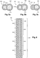
- the isolation section 110 may include a zone of mechanical weakness ( figure 5b ) adapted to allow cutting by pulling out.
- zone of mechanical weakness is meant a zone which breaks first as soon as a force is exerted on the isolation section.
- the zone of mechanical weakness can advantageously be arranged halfway between the branch segment 310b and the main conductor 210. Still advantageously, the zone of mechanical weakness can comprise a thinning along a cutting line of the section. isolation 110 ( Figures 5b and 5c ).
- each branch cable 300 can include a termination 330 in its extension ( figure 3a ), without secondary conductor.
- each termination 330 is arranged in the extension of a branch segment 310b.
- This termination 330 is particularly advantageous since it can, for example, play the role of initiating section for cutting by tearing.
- termination 330 of a branch cable 300 makes it possible to guarantee the electrical insulation of said cable.
- the outer surface of the coating sheath may, moreover, comprise a marking 400 making it possible to identify the terminations 330 of each of the branch cables 300.
- the marking 400 may for example be a paint mark or a difference in color of the coating sheath.
- the terminations 330 can be pre-weakened so as to facilitate the detachment of the branch cables 300 from said terminations 330.
- the pre-embrittlement can take the form of a notch, or a multitude of 'notches (dotted pre-embrittlement), formed in the coating sheath at each termination 330.
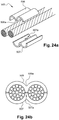
- the detachment of a branch cable at its termination 330 can also be implemented with a cutting pliers 800 ( figure 23 ).
- the branch cables 300 can have a length at least twenty times greater than the diameter of the branch segment. This dimensioning gives the branch cables flexibility making it possible to facilitate their reorientation and / or their positioning with a view to their electrical connection to equipment.
- the branch cables 300 form at least one row of branch cables 300, for example two rows ( figure 6 ), arranged in continuity with each other.
- This mode is particularly advantageous because it facilitates the manufacture of the cable by an extrusion process.
- the secondary conductors 310 can comprise an electrically insulating core around which is arranged a conductive material extending over the length of the secondary conductor.
- the electrically insulating core may in particular comprise a fibrous material, and in particular carbon fiber.
- the electrically insulating core is particularly advantageous because it makes it possible to strengthen the mechanical strength of the cable.
- the conductive material disposed around the core can include braided or twisted conductors.
- the secondary conductors 310 of the branch cables 300 arranged in a row comprise a common core.
- This core common to the secondary conductors 310 makes it possible to improve the mechanical strength, in particular the mechanical strength in tension, of the cable.
- initiating the detachment of a branch cable 300 at its termination may require cutting of the common core at said termination 330, in particular with a clamp 800 ( figure 23 ).
- a spacer may be arranged in the extension of each of the secondary conductors 310, and in particular of the secondary conductors 310 of the same row of branch cables 300.
- the spacers may have a diameter equivalent to the secondary conductors 310 which they extend.
- the spacers may in particular be in contact with the ends of two adjacent secondary conductors 310.
- the spacers may include kevlar.
- the contact between a contact section 310a and the main conductor 210 can be a direct contact.
- Direct contact means contact without the use of an intermediate element.
- direct contact can be obtained by tightening the contact section against the main conductor ( figure 7a ), or by contact between metallic wire strands emerging from the contact section and the main conductor ( figure 7b ), or by fusion between the contact section and the main conductor ( figure 7c ).
- the contact between the contact section 310a and the main conductor 210 is made by means of a part, called the contact part 400.
- the contact piece can in particular envelop, at least partially, the main conductor 210 and the contact section 310a.
- Such a contact piece 400 makes it possible to reinforce the cable 100 at the level of the contact between the secondary conductors 310 and the main conductor 210.
- this reinforcement offers greater resistance to tearing when detaching d 'a drop cable, and thus allows the insulation to be preserved after partial detachment of a drop cable 300.
- the contact piece 400 may for example be an electrically conductive piece clamping a branch cable 300 against the main cable 200.
- the contact piece 400 may comprise a metal strip encasing or surrounding the contact section 310a and the main conductor 210 at said contact section 310a.
- Contact part 400 as presented in the figure 8b , also makes it possible to limit detachment to the single section of the branch cables 300 comprising the branch segment 310b.
- the contact piece can be made of a flexible material 410, for example a polymer or a fabric, electrically insulating and intended to be wound around the main conductor and the secondary conductor. Still according to this variant, the flexible contact piece is also provided with a metal strip 420 intended to ensure electrical contact between the main conductor and the secondary conductor.
- the flexible material 410 can also include a slot 430.
- the contact piece 400 can take the form of mechanical reinforcement ( figure 9 ) which extends along the contact section 310a.
- the contact piece forms a connector 500 provided with a connecting member 505 which comprises a main part 510 and a secondary part 520 defining, respectively a main channel 510a and a secondary channel 520a parallel and separated by a central section 540 ( Figures 12a and 12b ).
- the main part 510 and / or the secondary part 520 are of tubular shape.
- the secondary channel 520a is particularly suitable for housing the contact section 310a by partial or total coating of the latter.
- the main channel 510a advantageously of an extension less than or equal to that of the secondary channel 520a, is adapted to accommodate a section of the main conductor 210, called the main contact section 210a, by partial or total coating of the latter.
- the connecting member 505 can be in one piece.
- one-piece connecting member means a connecting member formed in one piece.
- the connecting member 505 may be an assembly of an upper section 506 and a lower section 507 assembled at their central section, respectively, called, respectively, upper central section 506a and lower central section 507a.
- the upper section 506 and the lower section 507 are essentially symmetrical to each other with respect to a plane comprising the axes of elongation of the main channel 510a and the secondary channel 520a.
- each of the upper 506 and lower 507 sections can also be joined.
- connection means can be housed, before assembly of the upper 506 and lower 507 sections in one or the other of these two sections, and in particular at one or the other of the upper central section 506a and central section. lower 507a.
- the connecting member 505 can comprise an electrically conductive material, for example copper or aluminum.
- the connector 500 may also include connection means 600, made of an electrically conductive material, intended to electrically connect the main conductor 210 and the secondary conductor 310 as soon as they are housed, respectively, in the main channel 510a and in the secondary channel 520a.
- the connecting member 505 may comprise an electrically insulating material, for example a polymer, or an electrically conductive material.
- the electrical connection means 600 may in particular comprise a main contact section 610 and a secondary contact section 620 emerging respectively in the main channel 510a and in the secondary channel 520a, and linked by an intermediate section 630 ( Figures 12a, 13, 14 , 15a and 15b ).
- the electrical connection means can in particular include a fuse function, for example at the level of the intermediate section 630.
- This fuse function is particularly advantageous if the secondary conductors are of much smaller cross section than the main conductor, that is to say with a much lower current withstand.
- fuse function is meant a means which melts before as soon as the current passing through said means is greater than a threshold. Consequently, connection means which ensures a fuse function within the meaning of the present invention, is means which melts before the secondary conductors and the main conductor as soon as the current intensity exceeds a certain threshold.
- the secondary channel 520a can be arranged to house a secondary conductor 310 adapted to circulate a current lower than a predetermined current, and the connection means, in order to ensure the fuse function, can be adapted to melt as soon as when the current flowing through them exceeds by 40% the predetermined current.
- the intermediate section 630 can pass through the central section 540 at a passage communicating 540a between the main channel 510a and the secondary channel 520a ( figure 12a ).
- the communicating passage 540a can advantageously be opened at one end of the central section 540.
- the mounting of the electrical connection means 600 in the connecting member 505 can be carried out by sliding in the longitudinal direction of said connector 500.
- the main contact section 610 and the secondary contact section 620 can each form an elongated protrusion ( figure 12a ) or nipple-shaped, or pointed ( figure 9 ).
- the main contact section 610 and / or the secondary contact section 620 may have a shape complementary, respectively, to the surface defining the main channel 510, and the surface defining the secondary channel 520 ( Figures 13 and 14 ).
- complementary shape is meant a main or secondary contact section which conforms, at least in part, to the internal surface of the channel in which it is located.
- the intermediate section 630 can comprise a clip 630a ensuring the function of maintaining the electrical connection means at the level of the central section 540.
- main contact section 610 and the secondary contact section 620 relating to the first embodiment can also be implemented in the context of this second embodiment.
- the electrical connection means 600 may comprise a screw 601, in particular a headless screw.
- the screw 601 can in particular be screwed at the level of a bore 602 formed in the central section 540.
- the bore 602 is in particular arranged so as to present a lumen in each of the two main channels 510a and secondary 520a.
- the hole 602 has two lateral openings opening onto each main channels 510a and secondary 520a, revealing the thread of the screw 601.
- the thread of the screw 601 is intended to ensure electrical contact with the contact section 310a and with the main contact section 210a.
- This embodiment is also particularly advantageous because the thread of the screw 601 allows the main contact section 210a to be tightened in the main channel 510a and the contact section 310a in the secondary channel 520a.
- the main channel 510a can comprise a lateral slit over its entire length, so as to allow the insertion of the main contact section 210a into the main channel 510a by clipping ( Figures 12a, 12b and 13 ).
- the secondary channel 520a can comprise a lateral slit over its entire length, so as to allow the insertion of the contact section 310a into the secondary channel 310a by clipping ( Figures 12a, 12b and 13 ).
- the secondary channel 520a can comprise a stop, called the secondary stop 521, intended to prevent the complete crossing of the secondary channel by a secondary conductor.
- the secondary stop can be arranged at the end of the secondary channel.
- the secondary stop can separate the secondary channel into a first volume 522a, and a second volume 522b, the secondary contact section 520b emerging in the first volume 522a for example.
- the connector 500 can then advantageously be used to maintain two secondary conductors 310, said to be respectively the upstream conductor and the downstream conductor, successive of a row of branch cables 300. More particularly, the contact section 310a of the downstream conductor can be inserted into the first volume 522a so as to be in electrical contact with the main conductor 210 at the connector in question, while the end of the branch segment 310b of the upstream conductor is inserted into the second volume 522b. Also, it is understood that according to this configuration the secondary contact section emerges only in the first volume.
- the secondary stop 521 can take the form of at least one plug obstructing the passage in the secondary channel 510a ( figure 17a ).
- the secondary stop 521 can, according to a second alternative, take the form of two plugs providing an intermediate volume 522c between the first volume 522a and the second volume 522b ( figure 17b ). A cut at this intermediate volume 522c to initiate the detachment of the branch segment 310b does not call into question the electrical insulation of the upstream and downstream conductors.
- the secondary part is of tubular shape, and comprises a contraction zone forming the secondary stop 521.
- the contraction zone forms, in the same way as the two plugs of the second alternative, an intermediate volume 522c interposed between the first volume 522a and the second volume 522b ( figure 17c ).
- This third alternative is particularly advantageous insofar as the contraction zone is the seat of a mechanical weakness capable of facilitating the detachment of a branch cable.
- the contraction zone can advantageously be matched with a pre-weakened termination 330 of the multi-conductor electric cable so as to facilitate the detachment of the branch cable 300.
- the connector 500 can be provided with anchoring means 523 intended to hold the secondary conductor 310 in a locked position.
- the anchoring means 523 avoid, during the detachment of a branch cable 300, the separation of the secondary conductor 310 from the multi-conductor electric cable 100.
- the anchoring means 523 may in particular comprise projecting elements 523a intended to scratch the secondary conductor.
- the projecting elements 523a can be arranged on the internal surface of the secondary channel 520a ( Figures 18a and 18b ). Alternatively, illustrated in figure 19 , the projecting elements can be arranged on a ring 529 of shape complementary to the secondary channel 520a and inserted into said channel.
- the anchoring means 523 can be an integral part of the electrical connection means 600 and in particular be arranged on a secondary contact section 620.
- the main channel 510a can comprise, on its internal surface, protrusions, called main protrusions 524, intended to guide the main conductor 210 ( figure 20a ).
- the figure 21a represents the assembly of secondary conductors 310 with connectors 500, and in particular connectors therefore the secondary channel 520a is provided with a secondary stop 521.
- This step is then followed by the mounting of the main conductor 210 in the main channels 510a of the connectors 500 ( figure 21b ).
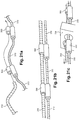
- the figures 22a to 22c and 23 illustrate the detachment of a drop cable 300 from the multi-conductor electric cable 100.
- figures 22a and 22b represent the cutout of the termination 330.
- the termination can be pre-weakened, and according to this condition, a simple tearing effort must be sufficient to initiate the detachment of the branch cable. Otherwise, for example in the presence of a core common to all the secondary conductors or in the presence of a connector 500 provided with a contraction zone separating the first volume and the second volume, it may be necessary to cut the termination 330 using a cutting pliers 800 as illustrated in the figure 23 .
- the cutting is then followed by a detachment of the branch cable 300 according to the isolation section 110 ( figure 22c ).
- the cutout is naturally stopped at the connector 500 which offers greater resistance to tearing.
- the present invention also relates to an assembly of multi-conductor electric cables 100 ( figure 10 ).
- the assembly comprises in particular a plurality of multi-conductor electric cables 100 comprising a common coating sheath, and electrically insulated from each other by said common sheath.
- the assembly can be flat ( figure 11a ) or star ( figure 11b ).
- the multi-conductor electric cable and / or the assembly devoid of ramifications and of relatively constant section, can advantageously be used to establish electrical connections in confined spaces.
- a multi-conductor electric cable according to the present invention is also advantageously used for electrical distribution, in particular for external networks requiring tight connections at a reasonable cost and / or difficulty.
- These cables can also be used for the electrical connection of solar panels, wind turbines.
Landscapes
- Connections Effected By Soldering, Adhesion, Or Permanent Deformation (AREA)
- Insulated Conductors (AREA)
- Cable Accessories (AREA)
Applications Claiming Priority (1)
| Application Number | Priority Date | Filing Date | Title |
|---|---|---|---|
| FR1859129A FR3086792B1 (fr) | 2018-10-02 | 2018-10-02 | Cable electrique multi-conducteurs |
Publications (1)
| Publication Number | Publication Date |
|---|---|
| EP3633690A1 true EP3633690A1 (de) | 2020-04-08 |
Family
ID=65244079
Family Applications (1)
| Application Number | Title | Priority Date | Filing Date |
|---|---|---|---|
| EP19199932.5A Withdrawn EP3633690A1 (de) | 2018-10-02 | 2019-09-26 | Mehradriges stromkabel |
Country Status (2)
| Country | Link |
|---|---|
| EP (1) | EP3633690A1 (de) |
| FR (1) | FR3086792B1 (de) |
Cited By (1)
| Publication number | Priority date | Publication date | Assignee | Title |
|---|---|---|---|---|
| FR3143179A1 (fr) * | 2022-12-13 | 2024-06-14 | Airbus Defence And Space Sas | Arrangement de câble électrique comprenant au moins unorgane de pincement du câble |
Citations (9)
| Publication number | Priority date | Publication date | Assignee | Title |
|---|---|---|---|---|
| JPS50138580U (de) * | 1974-04-30 | 1975-11-14 | ||
| JPS50147873U (de) * | 1974-05-27 | 1975-12-08 | ||
| JPS5118871A (en) * | 1974-08-07 | 1976-02-14 | Furukawa Electric Co Ltd | Tabungidensenno seizoho |
| JPS641425U (de) * | 1987-06-22 | 1989-01-06 | ||
| DE4120732A1 (de) | 1991-06-22 | 1992-01-16 | Jakob Schneider | Elektrisches kabel |
| DE4415525A1 (de) * | 1994-05-03 | 1995-11-09 | Plenty Hausleittechnik Gmbh | Vorrichtung zum Installieren elektrischer Betriebsmittel und Einrichtungen |
| JP2005332603A (ja) * | 2004-05-18 | 2005-12-02 | Yazaki Corp | 分岐付きケーブル |
| CN201750032U (zh) | 2010-07-22 | 2011-02-16 | 昆山勃盛电子有限公司 | 光伏供电系统集成线束 |
| US20150340125A1 (en) * | 2014-05-22 | 2015-11-26 | Hitachi Metals, Ltd. | Electric wire, harness, electrical circuit, fabric, garment and sheet |
-
2018
- 2018-10-02 FR FR1859129A patent/FR3086792B1/fr active Active
-
2019
- 2019-09-26 EP EP19199932.5A patent/EP3633690A1/de not_active Withdrawn
Patent Citations (9)
| Publication number | Priority date | Publication date | Assignee | Title |
|---|---|---|---|---|
| JPS50138580U (de) * | 1974-04-30 | 1975-11-14 | ||
| JPS50147873U (de) * | 1974-05-27 | 1975-12-08 | ||
| JPS5118871A (en) * | 1974-08-07 | 1976-02-14 | Furukawa Electric Co Ltd | Tabungidensenno seizoho |
| JPS641425U (de) * | 1987-06-22 | 1989-01-06 | ||
| DE4120732A1 (de) | 1991-06-22 | 1992-01-16 | Jakob Schneider | Elektrisches kabel |
| DE4415525A1 (de) * | 1994-05-03 | 1995-11-09 | Plenty Hausleittechnik Gmbh | Vorrichtung zum Installieren elektrischer Betriebsmittel und Einrichtungen |
| JP2005332603A (ja) * | 2004-05-18 | 2005-12-02 | Yazaki Corp | 分岐付きケーブル |
| CN201750032U (zh) | 2010-07-22 | 2011-02-16 | 昆山勃盛电子有限公司 | 光伏供电系统集成线束 |
| US20150340125A1 (en) * | 2014-05-22 | 2015-11-26 | Hitachi Metals, Ltd. | Electric wire, harness, electrical circuit, fabric, garment and sheet |
Cited By (2)
| Publication number | Priority date | Publication date | Assignee | Title |
|---|---|---|---|---|
| FR3143179A1 (fr) * | 2022-12-13 | 2024-06-14 | Airbus Defence And Space Sas | Arrangement de câble électrique comprenant au moins unorgane de pincement du câble |
| WO2024126424A1 (fr) * | 2022-12-13 | 2024-06-20 | Airbus Defence And Space Sas | Arrangement de câble électrique comprenant au moins un organe de pincement du câble |
Also Published As
| Publication number | Publication date |
|---|---|
| FR3086792B1 (fr) | 2023-06-02 |
| FR3086792A1 (fr) | 2020-04-03 |
Similar Documents
| Publication | Publication Date | Title |
|---|---|---|
| US9515423B2 (en) | Tapered ground strap shield connector | |
| EP3758154B1 (de) | Stromanschlussmodul mit verriegelungs-/entriegelungssystem der stromkabelenden in dem modul, klemmleiste, die eine vielzahl von unabhängigen anschlussmodulen umfasst | |
| EP3758161A1 (de) | Stromanschlusseinheit, die ein anschlussmodul und stromkabelenden umfasst, die in diesem modul je nach gewünschter einschubposition verriegelt/entriegelt werden können, und klemmleiste, die eine vielzahl von unabhängigen anschlussmodulen umfasst | |
| EP2805392B1 (de) | Verbindungsverfahren, spannungsausgleichsnebenschaltung und spannungsausgleichsverbindungsrückführungsnetz in einer nichtleitenden architektur | |
| EP3758165B1 (de) | Anschlussmodul, anschlusseinheit mit klemmleiste mit einer vielzahl von solchen anschlussmodulen und luftfahrzeugstruktur mit solcher anschlusseinheit | |
| FR2990076A1 (fr) | Harnais de liaison de retour de courant, ainsi que procede de montage sur un cadre de fuselage composite | |
| FR3057717A1 (fr) | Systeme sous-marin de raccordement electrique | |
| FR2987504A1 (fr) | Bloc fonctionnel de mesure pour poste de distribution moyenne tension | |
| EP3633794B1 (de) | Anschluss | |
| EP3633690A1 (de) | Mehradriges stromkabel | |
| EP4557528B1 (de) | Kraftlose kupplungsleistungskontaktbaugruppe, leistungsanschlussmodul mit einer solchen baugruppe zum klemmen eines stromkabelabschlusses | |
| EP3555963B1 (de) | Elektrisches verbindungselement mit einem kontaktelement und herstellungsverfahren dafür | |
| EP2634876B1 (de) | Mittelspannungsverbindungsleiste mit einer ebener Schnittstelle und mit einer konischer Steckverbindung | |
| EP2634869B1 (de) | Stecker mit flacher Anschlussschnittstelle und eine Mittelspannungsanlage mit einem derartigen Stecker. | |
| EP0933856B1 (de) | Kaltschrumpfbare Dichtungsmuffe für elektrische Kabel | |
| FR2987505A1 (fr) | Dispositif d'evacuation des gaz pour unite fonctionnelle moyenne tension et poste de distribution le comprenant | |
| FR2990570A1 (fr) | Embout de branchement pour cable d'alimentation electrique isole et procede de fabrication de cet embout de branchement | |
| CA2871224C (fr) | Procede de connexion de conducteurs d'une nappe souple de liaison equipotentielle, ainsi que outil de sertissage, connecteurs et harnais equipe de tels connecteurs | |
| EP4376223B1 (de) | Anschlussleiste mit einem leiterrahmen und zugehörige elektrische reihenklemme | |
| FR2968138A1 (fr) | Ensemble de liaison electrique forme par un cable electrique haute tension et un dispositif de connexion | |
| FR2962600A1 (fr) | Dispositif de raccordement electrique | |
| EP4131659A1 (de) | Steckdosenmechanismus und entsprechende steckdose | |
| EP4557526A1 (de) | Leistungsanschlussmodul zum klemmen eines elektrischen kabelabschlusses durch ein blatt, dessen mindestens ein verformbares teil zur bildung eines anschlussblockteils einer verbindungsanordnung bildet | |
| EP2109192B1 (de) | Steckersatz und Verkabelungsverfahren eines elektrischen Kabels in einem solchen Steckersatz | |
| FR2999347A1 (fr) | Connecteur type rj45 perfectionne |
Legal Events
| Date | Code | Title | Description |
|---|---|---|---|
| PUAI | Public reference made under article 153(3) epc to a published international application that has entered the european phase |
Free format text: ORIGINAL CODE: 0009012 |
|
| STAA | Information on the status of an ep patent application or granted ep patent |
Free format text: STATUS: THE APPLICATION HAS BEEN PUBLISHED |
|
| AK | Designated contracting states |
Kind code of ref document: A1 Designated state(s): AL AT BE BG CH CY CZ DE DK EE ES FI FR GB GR HR HU IE IS IT LI LT LU LV MC MK MT NL NO PL PT RO RS SE SI SK SM TR |
|
| AX | Request for extension of the european patent |
Extension state: BA ME |
|
| STAA | Information on the status of an ep patent application or granted ep patent |
Free format text: STATUS: THE APPLICATION IS DEEMED TO BE WITHDRAWN |
|
| 18D | Application deemed to be withdrawn |
Effective date: 20201009 |