EP2805597B1 - Steuergeräte, Systeme und Verfahren für eine selbstangetriebene Maschine - Google Patents
Steuergeräte, Systeme und Verfahren für eine selbstangetriebene Maschine Download PDFInfo
- Publication number
- EP2805597B1 EP2805597B1 EP14169273.1A EP14169273A EP2805597B1 EP 2805597 B1 EP2805597 B1 EP 2805597B1 EP 14169273 A EP14169273 A EP 14169273A EP 2805597 B1 EP2805597 B1 EP 2805597B1
- Authority
- EP
- European Patent Office
- Prior art keywords
- aspects
- control
- machinery
- self
- controls
- Prior art date
- Legal status (The legal status is an assumption and is not a legal conclusion. Google has not performed a legal analysis and makes no representation as to the accuracy of the status listed.)
- Not-in-force
Links
- 238000000034 method Methods 0.000 title claims description 23
- 230000005540 biological transmission Effects 0.000 claims description 48
- 238000003825 pressing Methods 0.000 claims description 16
- 230000033001 locomotion Effects 0.000 description 17
- 230000001276 controlling effect Effects 0.000 description 13
- 230000008859 change Effects 0.000 description 6
- 238000012546 transfer Methods 0.000 description 3
- 230000003247 decreasing effect Effects 0.000 description 2
- 238000010586 diagram Methods 0.000 description 2
- 230000008569 process Effects 0.000 description 2
- 230000003213 activating effect Effects 0.000 description 1
- 230000001154 acute effect Effects 0.000 description 1
- 238000003491 array Methods 0.000 description 1
- 230000009286 beneficial effect Effects 0.000 description 1
- 230000015572 biosynthetic process Effects 0.000 description 1
- 238000007664 blowing Methods 0.000 description 1
- 238000004891 communication Methods 0.000 description 1
- 230000000694 effects Effects 0.000 description 1
- 230000000977 initiatory effect Effects 0.000 description 1
- 230000007246 mechanism Effects 0.000 description 1
- 230000002035 prolonged effect Effects 0.000 description 1
- 230000001105 regulatory effect Effects 0.000 description 1
- 238000009877 rendering Methods 0.000 description 1
- 238000011160 research Methods 0.000 description 1
- 230000004044 response Effects 0.000 description 1
- 238000012163 sequencing technique Methods 0.000 description 1
- 230000007704 transition Effects 0.000 description 1
- 238000013519 translation Methods 0.000 description 1
Images




Classifications
-
- A—HUMAN NECESSITIES
- A01—AGRICULTURE; FORESTRY; ANIMAL HUSBANDRY; HUNTING; TRAPPING; FISHING
- A01D—HARVESTING; MOWING
- A01D34/00—Mowers; Mowing apparatus of harvesters
- A01D34/01—Mowers; Mowing apparatus of harvesters characterised by features relating to the type of cutting apparatus
- A01D34/412—Mowers; Mowing apparatus of harvesters characterised by features relating to the type of cutting apparatus having rotating cutters
- A01D34/63—Mowers; Mowing apparatus of harvesters characterised by features relating to the type of cutting apparatus having rotating cutters having cutters rotating about a vertical axis
- A01D34/67—Mowers; Mowing apparatus of harvesters characterised by features relating to the type of cutting apparatus having rotating cutters having cutters rotating about a vertical axis hand-guided by a walking operator
- A01D34/68—Mowers; Mowing apparatus of harvesters characterised by features relating to the type of cutting apparatus having rotating cutters having cutters rotating about a vertical axis hand-guided by a walking operator with motor driven cutters or wheels
-
- G—PHYSICS
- G05—CONTROLLING; REGULATING
- G05G—CONTROL DEVICES OR SYSTEMS INSOFAR AS CHARACTERISED BY MECHANICAL FEATURES ONLY
- G05G13/00—Manually-actuated control mechanisms provided with two or more controlling members and also two or more controlled members
-
- A—HUMAN NECESSITIES
- A01—AGRICULTURE; FORESTRY; ANIMAL HUSBANDRY; HUNTING; TRAPPING; FISHING
- A01D—HARVESTING; MOWING
- A01D34/00—Mowers; Mowing apparatus of harvesters
- A01D34/01—Mowers; Mowing apparatus of harvesters characterised by features relating to the type of cutting apparatus
- A01D34/412—Mowers; Mowing apparatus of harvesters characterised by features relating to the type of cutting apparatus having rotating cutters
- A01D34/63—Mowers; Mowing apparatus of harvesters characterised by features relating to the type of cutting apparatus having rotating cutters having cutters rotating about a vertical axis
- A01D34/67—Mowers; Mowing apparatus of harvesters characterised by features relating to the type of cutting apparatus having rotating cutters having cutters rotating about a vertical axis hand-guided by a walking operator
- A01D34/68—Mowers; Mowing apparatus of harvesters characterised by features relating to the type of cutting apparatus having rotating cutters having cutters rotating about a vertical axis hand-guided by a walking operator with motor driven cutters or wheels
- A01D34/6806—Driving mechanisms
- A01D34/6812—Braking or clutching mechanisms
-
- A—HUMAN NECESSITIES
- A01—AGRICULTURE; FORESTRY; ANIMAL HUSBANDRY; HUNTING; TRAPPING; FISHING
- A01D—HARVESTING; MOWING
- A01D34/00—Mowers; Mowing apparatus of harvesters
- A01D34/01—Mowers; Mowing apparatus of harvesters characterised by features relating to the type of cutting apparatus
- A01D34/412—Mowers; Mowing apparatus of harvesters characterised by features relating to the type of cutting apparatus having rotating cutters
- A01D34/63—Mowers; Mowing apparatus of harvesters characterised by features relating to the type of cutting apparatus having rotating cutters having cutters rotating about a vertical axis
- A01D34/67—Mowers; Mowing apparatus of harvesters characterised by features relating to the type of cutting apparatus having rotating cutters having cutters rotating about a vertical axis hand-guided by a walking operator
- A01D34/68—Mowers; Mowing apparatus of harvesters characterised by features relating to the type of cutting apparatus having rotating cutters having cutters rotating about a vertical axis hand-guided by a walking operator with motor driven cutters or wheels
- A01D2034/6843—Control levers on the handle of the mower
-
- Y—GENERAL TAGGING OF NEW TECHNOLOGICAL DEVELOPMENTS; GENERAL TAGGING OF CROSS-SECTIONAL TECHNOLOGIES SPANNING OVER SEVERAL SECTIONS OF THE IPC; TECHNICAL SUBJECTS COVERED BY FORMER USPC CROSS-REFERENCE ART COLLECTIONS [XRACs] AND DIGESTS
- Y10—TECHNICAL SUBJECTS COVERED BY FORMER USPC
- Y10T—TECHNICAL SUBJECTS COVERED BY FORMER US CLASSIFICATION
- Y10T74/00—Machine element or mechanism
- Y10T74/20—Control lever and linkage systems
- Y10T74/20207—Multiple controlling elements for single controlled element
- Y10T74/20372—Manual controlling elements
- Y10T74/20384—Levers
-
- Y—GENERAL TAGGING OF NEW TECHNOLOGICAL DEVELOPMENTS; GENERAL TAGGING OF CROSS-SECTIONAL TECHNOLOGIES SPANNING OVER SEVERAL SECTIONS OF THE IPC; TECHNICAL SUBJECTS COVERED BY FORMER USPC CROSS-REFERENCE ART COLLECTIONS [XRACs] AND DIGESTS
- Y10—TECHNICAL SUBJECTS COVERED BY FORMER USPC
- Y10T—TECHNICAL SUBJECTS COVERED BY FORMER US CLASSIFICATION
- Y10T74/00—Machine element or mechanism
- Y10T74/20—Control lever and linkage systems
- Y10T74/20576—Elements
- Y10T74/20582—Levers
- Y10T74/20612—Hand
Definitions
- the present subject matter generally relates to self-propelled machinery and related methods and, more particularly, to control devices, systems, and related methods of driving a lawn mower.
- Self-propelled machines such as lawn mowing machines, snow throwing or snow blowing machines, tillers, and the like, often provide handles on which controls are mounted for manipulation by operators or users of such machines.
- Conventional "walk behind" types of self-propelled machines typically have a handle extending behind a main operative assembly of the machine for gripping by the operator as the operator walks behind the machine during movement thereof in a forward direction.
- one or more controls are mounted on the handle for the user to manipulate while gripping the handle and operating the machine.
- recent marketing research indicates that many consumers of self-propelled machines would prefer more intuitive and user-friendly control mechanisms in order to simplify use of the machines.
- US-7762050 B1 and EP-A1-2025217 each disclose a control device for a self-propelled machine comprising: a central portion disposed between first and second gripping portions; and a pressure sensitive trigger control provided over the first gripping portion; wherein trigger control is configured to reduce a speed of machinery by actuating a cable.
- US-A-3841069 discloses a self-propelled machine whose forward speed is regulated by actuating a potentiometer in order to vary an electric signal.
- the invention provides a self-propelled machine and a method in accordance with claims 1 and 9.
- the self-propelled machine and methods described herein provide improved control over self-propelled machinery, easier speed changes in self-propelled machinery, improved ease-of operation of self-propelled machinery, improved comfort during operation of self-propelled machinery and lower operator fatigue.
- Such control devices and systems can be ergonomic, easy to understand, and easy to manipulate controls allowing for simplified one-handed operation of the self-propelled machinery.
- control devices, systems, and related methods for controlling the speed and/or forward motion of self-propelled machinery, such as lawn mowers, snow throwers, tillers, delivery carts, lifts, floor scrubbers, and the like.
- control devices, systems, and related methods can comprise electric controls such as a push button start for starting the engine of the machinery and/or one or more potentiometers for setting, slowing, and/or stopping forward motion of the machinery.
- the use and control of self-propelled machinery via electric controls, such as one or more potentiometers provides advantageous and unexpected results including easier speed changes of the machinery, improved one-handed control over the machinery, improved comfort, lower operator fatigue, and/or improved ease-of-operation of the self-propelled machinery.
- control devices, systems, and methods described herein can be used with machinery having a hybrid motor or engine, including a gas motor and an electric transmission.
- controls, systems, and methods described herein can control aspects of the electric transmission, which can transmit power to one or more wheels of the self-propelled machinery.
- controls, systems, and methods described herein can comprise electric controls configured to start and/or control aspects of the electric transmission.
- controls, systems, and methods described herein can comprise one or more pressure sensitive controls which can be engaged during or as an operator steers the self-propelled machinery.
- the pressure sensitive controls can be disposed over gripping portions of the control device or system, thereby allowing one-handed (e.g., single handed) control over and/or operation of the self-propelled machinery.
- controls, systems, and methods described herein can comprise a first pressure sensitive control engaged to start the transmission (e.g., push button start) of the self-propelled machinery, a rotatable control for setting a maximum speed, and one or more other pressure sensitive controls for slowing and/or stopping the self-propelled machinery.
- one or more of the pressure sensitive controls can comprise a potentiometer adapted to electrically communicate with the transmission.
- the rotatable control can comprise a potentiometer adapted to electrically communicate with the transmission.
- the one or more electric controls can electrically communicate with the transmission via an electric control unit.
- the electrical control unit can comprise an electrical device configured to provide operational sequencing for a hybrid engine.
- the subject matter described herein may be implemented in software in combination with hardware and/or firmware.
- the subject matter described herein may be implemented in software executed by a processor (e.g., a hardware-based processor), microprocessor, and/or microcontroller of electric control unit.
- the subject matter described herein may be implemented using a non-transitory computer readable medium having stored thereon computer executable instructions that when executed by the processor of a computer control the computer to perform steps.
- Exemplary computer readable media suitable for implementing the subject matter described herein include non-transitory devices, such as disk memory devices, logic devices, logic transistors, chip memory devices, programmable logic devices, such as field programmable gate arrays, and application specific integrated circuits.
- a computer readable medium that implements the subject matter described herein may be located on a single device or computing platform or may be distributed across multiple devices or multiple computing platforms.
- controller refers to software in combination with hardware and/or firmware for implementing features described herein.
- a controller may include a microprocessor, a processor, or a microcontroller.
- Potentiometer can comprise any device adapted to vary resistance, voltage, or current within a circuit. Potentiometers can have three terminals or contacts. Two terminals can comprise end terminals and at least one other terminal (e.g., the wiper) can be movable to vary resistance as is measured with respect to it and either one of the end terminals.
- references to a structure being formed “on” or “above” another structure or portion contemplates that additional structure, portion, or both may intervene. References to a structure or a portion being formed “on” another structure or portion without an intervening structure or portion are described herein as being formed “directly on” the structure or portion.
- relative terms such as “on”, “above”, “upper”, “top”, “lower”, or “bottom” are used herein to describe one structure's or portion's relationship to another structure or portion as illustrated in the figures. It will be understood that relative terms such as “on”, “above”, “upper”, “top”, “lower” or “bottom” are intended to encompass different orientations of the package or component in addition to the orientation depicted in the figures. For example, if the package or component in the figures is turned over, structure or portion described as “above” other structures or portions would now be oriented “below” the other structures or portions. Likewise, if the package or component in the figures are rotated along an axis, structure or portion described as “above”, other structures or portions would be oriented “next to" or “left of” the other structures or portions.
- Figure 1 is a top plan view of one embodiment of a control device generally designated 10, for use with self-propelled machinery such as a lawn mower, snow thrower, tiller, and the like.
- control device 10 can comprise a distal end portion of a handle that extends behind a main operative assembly of the self-propelled machinery.
- control device 10 can comprise one or more grips or gripping portions of a handle to which an operator can grasp while walking behind the machine during movement thereof.
- control device 10 can advantageously comprise one or more controls for activating and/or controlling one or more engines of the machinery, and/or for controlling a speed and/or motion thereof.
- the one or more controls can be intuitive and/or easily reachable from the one or more gripping portions.
- Control device 10 can advantageously provide for one-handed control and steering of the self-propelled machinery.
- control device 10 can comprise a handle, or portion thereof, having a first gripping portion or a first leg, generally designated 12A, a second gripping portion or second leg, generally designated 12B, and a central portion, generally designated 14 disposed therebetween.
- first leg 12A can be spaced apart from and angled with respect to second leg 12B. This can advantageously improve the ergonomic and aesthetic aspects of device 10. That is, angled gripping portions may be more comfortable and have a more natural feel to the operator.
- First leg 12A can be disposed at an acute angle (e.g., less than 90°), an obtuse angle (e.g., greater than 90°), or approximately orthogonal with respect to second leg 12B .
- first and second legs 12A and 12B can be provided in a substantially V-shape or V-shaped formation.
- one or more controls can be disposed on central portion 14 and/or on legs 12A and 12B. Such controls can advantageously be centralized with respect to the operator, and easily reachable from first and second legs 12A and 12B.
- central portion 14 can comprise a pressure-sensitive or "push" control, such as a push button start 16, and a second rotatable control, such as a knob setting 18 or dial disposed thereon.
- push button start 16 and setting 18 can be disposed on a first surface or side 20 of device 10.
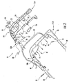
- One or more controls can also be disposed on an opposing second surface or side 22 of device as illustrated in Figure 2 .
- setting 18 comprises a speed setting, whereby an operator can set a maximum speed of the self-propelled machinery.
- push button start 16 and setting 18 can comprise electric controls having an electrical aspect as opposed to purely mechanical controls. That is, in some aspects, push button start 16 and setting 18 can electrically communicate to a centralized control unit (see e.g., Figure 4 ) for controlling portions of a gas, electric, and/or hybrid engine to increase speed, decrease speed, set and hold (e.g., maintain) speed, and/or altogether stop forward motion of the machinery. In some aspects, push button start 16 and setting 18 can electrically communicate with control unit ( Figure 4 ) via transmitting electrical pulses and/or electrical signals transmitted across one or more physical or electrical interfaces (not shown) of control unit. In some aspects, electrical signal carried via device 10 can be directly or indirectly communicated via one or more electrically conductive wires (not shown) to a control unit of the self-propelled machinery.
- setting 18 can comprise a dial that can be rotated or moved clockwise and/or counterclockwise with respect to legs, operator, and/or central portion 14 of device 10 for setting a maximum speed. That is, a maximum speed associated with the forward motion of the machinery can be easily controlled by manipulating or physically adjusting setting 18.
- speed of the machinery can be selectively adjusted by an operator (e.g., to a higher or lower maximum speed) simply by twisting or rotating one or more portions of speed setting 18.
- speed setting 18 comprises an intuitive speed setting dial, which is easy to understand and not overly complex.
- a maximum speed can be intuitively increased by rotating setting 18 clockwise and intuitively decreased by rotating setting 18 counterclockwise with respect to central portion 14.
- Such intuitive, easily manipulated, and easily reachable (e.g., centralized with respect to the operator) controls can advantageously allow machinery incorporating device 10 to be used, operated, and, therefore, purchased by larger portions of the general population, including elderly consumers.
- Control device 10 can comprise comfortable and ergonomic gripping portions, whereby an operator can steer the machinery. Ergonomic gripping portions or legs (12A and 12B) can be coupled to a centralized control area from which an operator can set and control a speed, increase or decrease speed, and/or start and stop the engine of the machinery.
- control device 10 can comprise a first, rear cover 24 and a second, front cover 26. Rear cover 24 and front cover 26 can be physically coupled together via one or more mechanical fasteners M to form first and second legs 12A and 12B, respectively, and central portion 14.
- mechanical fasteners can comprise screws, however, any fastener, including pins, clips, and/or hooks, can be provided.
- first and second handles 28 and 30 can comprise hollow pipes configured to house electrical wires or other electrical components (not shown) configured to communicate electrical pulses or signals from controls (e.g., push button start 16 and setting 18 ) to an electrical control unit ( Figure 4 ) for controlling aspects of the self-machinery, including speed (e.g., speed of one or more wheels).
- controls e.g., push button start 16 and setting 18
- an electrical control unit Figure 4
- device 10 can be attached to first and second handles 28 and 30 of a walk behind machine, such as a lawn mower, via mechanical fasteners M.
- first and second handles 28 and 30 can be coupled to a rear portion of a lawn mower deck via any suitable means, and can extend upwardly therefrom at an angle appropriate for providing device 10 at a comfortable position for grasping and manipulation by an operator. In some aspects, the position at which device 10 is located is adjustable, so as to be even more comfortable to an operator thereof.
- setting 18 comprises a first potentiometer 32 configured for setting a maximum speed of the mower. That is, in some aspects, rotation of setting 18 can be configured to actuate or engage first potentiometer 32 thereby varying a resistance, voltage, or current associated with an electrical signal.
- First potentiometer 32 can electrically communicate with a controller or control unit ( Figure 4 ), which can be used to control a maximum amount of power transmitted to wheels of the self-propelled machinery.
- the maximum amount of power transmitted to the wheels of the self-propelled machinery can correspond to a maximum speed of the machine.
- the controller or control unit ( Figure 4 ) can electrically communicate with an electric transmission, which can deliver drive power to one or more wheels of the self-propelled machinery.
- first potentiometer 32 can be controlled by turning of a dial or knob setting (e.g., setting 18 ) which can correspond to a maximum speed to be set and maintained.
- setting 18 and potentiometer 32 can be mechanically connected such that turning setting 18 can move at least one contact or terminal of potentiometer 32, thereby varying resistance or voltage of the electrical current.
- An inner frame 34 or frame portion of device 10 can be used to support and hold portions of electrical controls between rear and front covers 24 and 26, respectively.
- Device 10 can further comprise one or more controls disposed on a second side 22 of device 10, portions of which can be supported and held via frame 34.
- one or more pressure sensitive controls can be provided on a second side 22 of device 10, wherein an operator of self-propelled machinery can control further aspects of the machine by applying pressure to the controls.
- device 10 can comprise one or more pressure-sensitive or "squeezable" trigger controls 36.
- trigger controls 36 can be configured to adjust a speed of the self-propelled machinery. That is, the forward motion of the machine can be slowed and/or stopped via applying pressure to one or more trigger controls 36, for example, by squeezing trigger control against gripping portions of device 10.
- trigger controls 36 can connect with and extend through portions of frame 34. Trigger controls 36 can also extend through openings or apertures A of second side 22 of front cover 26 allowing controls 36 to be easily manipulated while gripping first and/or second legs 12A and 12B. Notably, the self-propelled machinery can be slowed and/or stopped by squeezing just one trigger control 36 disposed on either side of device 10 thereby providing easy, simple, one-handed operation of the machinery. This can contribute to prolonged energy and/or decreased fatigue of operators of self-propelled machinery described herein.
- each trigger control 36 can be adapted to actuate and/or engage a second potentiometer 38.
- each trigger control 36 can be used to vary a resistance an electrical signal sent to a controller via a respective second potentiometer 38.
- Pressing trigger controls 36 can actuate or move at least one contact or terminal of each potentiometer 38 mechanically connected thereto, thereby varying resistance or voltage of resultant electrical current carried by device 10.
- Second potentiometers 38 can be used to slow or stop forward motion of the self-propelled machinery by varying the voltage or resistance of an electrical current supplied to a controller.
- device 10 can comprise multiple electric controls, including at least one rotatable control, at least one pressure sensitive (i.e., trigger) control, and at least one push control.
- Device 10 can advantageously provide intuitive functional controls for improving ease-of-operation and enabling easy speed changes.
- Device 10 can enhance self-propelled machinery by allowing one handed operation, lowering operator fatigue, and improving the ease at which the machine can be turned or directed during operation.
- device 10 can further comprise a lever 40.
- lever 40 can comprise a brake lever which can be pulled, pivoted, and/or otherwise moved to release and/or activate a brake.
- lever 40 can be configured to pivot about portions of device 10 and rotate, thereby pulling a brake cable.
- lever 40 can comprise a cable or non-cable component that can be adapted to transfer a force or actuation to a brake via translation and/or a change in tension.
- FIG. 3 a perspective side view of control device 10 during operation of self-propelled machinery is illustrated.
- an operator can physically manipulate one or more electric controls while gripping at least one leg portion (e.g., 12A ) of device 10.
- an operator can apply pressure to trigger controls 36 while gripping one or both leg portions, for example, by wrapping fingers around at least first leg portion 12A and squeezing trigger control 36.
- the trigger control 36 can be squeezed inwardly towards rear cover 24 of device 10 in the direction D1.
- lever 40 can be pulled upwardly towards rear cover 24 of device 10 and pivot about portions of front cover 26 as shown.
- pulling lever 40 in a direction D2 towards rear cover 24 can release the brake.
- an operator can easily control the speed of the machinery via squeezing either one or both electric trigger controls 36 while gripping and steering the walk behind machine.
- Control device 10 can advantageously provide one-handed operation of self-propelled machinery.
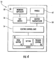
- FIG 4 is a block diagram of a control system, generally designated 50, for controlling aspects of self-propelled machinery 52, such as a lawn mower.
- Machinery 52 can comprise a control device 10, as described hereinabove, which can be electrically connected to and/or electrically communicate with an electric control unit 54 or controller.
- Control device 10 can electrically communicate with electric control unit 54 via one or more interfaces (not shown), which in turn can communicate with and/or control aspects of an electric transmission 58.
- electric transmission 58 can be powered via a gas motor 56 using an actuator or generator.
- machinery 52 can comprise a hybrid engine having both an electric transmission 58 and a gas motor 56.
- Gas motor 56 can be adapted to directly power a working implement 60, such as a lawn mower blade (e.g., or a tilling blade, snow throwing implement, floor scrubber, etc.) and electric transmission 58.
- Electric transmission 58 can be adapted to transfer and/or supply power directly to one or more wheels 62 of the machinery 52.
- one or more electric controls of device 10 can be used to set, adjust, and/or control the speed at which one or more wheels 62 operate.
- the speed at which one or more wheels 62 operate can be selectively controlled and varied during operation of machinery 52 via applying pressure to one or more trigger controls 36 while gripping one or more leg portions (e.g., 12A, 12B, Figures 1 and 2 ) of control device 10 or control handle.
- gas motor 56 can be configured to transfer power to and drive one or more wheels 62 via transmission 58 in any suitable manner, thereby rendering machinery 52 self-propelled in response to control by an operator.
- machinery 52 can comprise many different types and/or structures self-propelled machinery, such as lawn mowers, in addition to those described hereinabove which are known to persons skilled in the art, and therefore are not further described.
- Electric transmission 58 can comprise a variable-speed electric transmission, and in some aspects can comprise a continuously variable-speed transmission. An operator can control the output speed of a continuously variable-speed electric transmission 58, and thus the speed of one or more driving wheels 62, over a continuous or substantially continuous range between a zero, or minimal speed and a maximum speed established via setting 18.
- more than one trigger control 36 can be configured to electrically communicate to control unit 54 via a respective potentiometer.
- control unit 54 can be configured to interpret a variation in signals as an incremental decrease in speed.
- control unit 54 can be further configured to receive electrical input or signals from an ignition control and a rotatable dial for setting a maximum speed, such as push button start 16 and setting 18, respectively.
- push button start 16 can comprise an electrical ignition control configured to communicate to control unit 54 an operator's instruction that the engine (e.g., comprising motor 56 and transmission 58 ) is to be started.
- setting 18 can send signals to control unit 54 via a potentiometer.
- Control unit 54 can be configured to interpret variation in signals as a set maximum speed.
- Control unit 54 can further be configured, for example, to enable an operator to start or stop movement of working implement 60 (e.g., rotation of a mower blade) by instructing transmission 58 to open or close an interface clutch via control device 10.
- control unit 54 can receive a signal to activate gas motor 56 and transmission 58, and, therefore, working implement 60 and wheels 62 thereby allowing machinery 52 to be propelled using the power generated by gas motor 56 as transferred by transmission 58.
- Figure 5 is a flow chart illustrating an exemplary method, generally designated 70, for controlling aspects of self-propelled machinery via control devices and systems described hereinabove.
- the method can consist of a starting phase 70A, a driving phase 70B, and a stopping phase 70C.
- the starting phase 70A can comprise pulling the brake lever as illustrated at block 72.
- the lever can be pulled back towards a rear cover of a control device to release a brake as described hereinabove. Pulling the brake lever towards a central portion of control device can release the brake and prepare the machine for the driving phase.
- the operator can press the start button (e.g., push button start 16, Figure 1 ) to start the engine of the machinery, which can include starting a gas motor and powering an electric transmission.
- the start button can comprise an electric device adapted to electrically communicate with a control unit for controlling aspects of the engine via the electric transmission.
- Blocks 76, 78, and 80 illustrate aspects of driving phase 70B.
- an operator can set a maximum cruising speed using an electric control (e.g., setting 18, Figure 1 ) disposed on control device 10 ( Figures 1-4 ).
- a maximum cruising speed can be intuitively set via rotating a dial or knob (e.g. setting 18 ) clockwise and/or counterclockwise over control device 10 ( Figures 1-4 ).
- the maximum cruising speed can be set using electric signals communicated from a first potentiometer ( 32, Figure 2 ) to a control unit ( 54, Figure 4 ).
- the operator can place hands around the control device (e.g., 10, Figures 1-4 ) and apply pressure via squeezing, pressing, and/or pulling back on one or both trigger controls (e.g., 36, Figures 2-4 ) fully and then releasing the same to start the electric transmission (e.g., 56, Figure 4 ).
- Starting the transmission can transmit power to one or more wheels of the self-propelled machinery. The wheels can gradually propel the machinery to the maximum speed set at block 76.
- an operator can use electric controls to slow or stop the machinery via electrically communicating the desire to slow or stop to the electric transmission (e.g., 56, Figure 4 ) via applying subsequent pressure to trigger controls.
- the one or more wheels can be slowed or stopped via using trigger controls (e.g., 36, Figures 1-4 ).
- An electric control unit e.g., 54, Figure 4
- the machine can be stopped via stopping the engine (e.g., motor and transmission).
- releasing the brake lever (e.g., 40 Figures 2 , 3 ) from the control device can engage the brake and turn off the motor.
- releasing the brake lever (e.g., 40, Figures 2 , 3 ) can indicate the desire to stop the machinery, and disengage the working implement (e.g., cutting blade, tilling blade, etc.) and discontinue propelling the one or more wheels.
- Control device 90 can be used within a control system for sending electrical pulses or signals to an electrical control unit (e.g., Figure 4 ) and transmission.
- control device 90 can be used to control various aspects of self-propelled machinery, such as a lawn mower, snow thrower, tiller, and the like.
- control device 90 can be disposed at a distal end portion of one or more handles 92 that extend distally away from a main operative assembly (e.g., a mower deck) of the self-propelled machinery (not shown).
- control device 90 can comprise a handle, or portion thereof, having one or more grips or gripping portions to which an operator can grasp while walking behind the machine during movement thereof.
- Control device 90 can further comprise one or more controls adapted to electrically activate and/or control an engine of the machinery, or portions thereof, and/or for controlling a speed and/or motion thereof.
- the one or more controls can be electric and centralized with respect to the operator and/or control device 90.
- the one or more controls can be disposed over the one or more gripping portions of control device 90, and can comprise intuitive, easy to reach controls with respect to the gripping portions, such that an operator is not required to lift a hand from the gripping portion in order to slow or stop the machinery.
- control devices described herein can allow for one-handed operation and control of the self-propelled machinery.
- the gripping portions can be angled, allowing for improved comfort to an operator, easier steering of the machinery, and lower operator fatigue.
- control device 90 can comprise a first gripping portion or a first leg, generally designated 94A, a second gripping portion or second leg, generally designated 94B , and a central portion, generally designated 96, disposed therebetween.
- first leg 94A can be spaced apart from and angled with respect to second leg 94B, improving the ergonomic and aesthetic aspects thereof.
- each of first and second leg 94A and 94B can comprise an elongated body that can be substantially cylindrical in shape and comprise a front cover and a rear cover as described in Figure 2 . Front and rear covers can be joined together in any suitable manner, such as, for example, with mechanical fasteners (not shown) seated within fastener holes. It is also envisioned in accordance with the present disclosure that first and second legs 94A and 94B can be formed as a unitary structure.
- one or more controls can be disposed over a central portion 96 of device 90 and/or over portions of first and second legs 94A and 94B of device 90. Such controls can advantageously be centralized with respect to the operator, and easily reachable from first and second legs 94A and 94B, respectively.
- central portion 96 can comprise a first pressure-sensitive or "push" control, such as a push button start 98, and a second rotatable control, such as a rotatable knob setting 100 or dial disposed thereon.
- push button start 98 and setting 100 can be disposed on a first surface or side of device 90.
- One or more controls can also be disposed on an opposing second surface or back side of device.
- setting 100 comprises a speed setting, whereby an operator can set a maximum speed of the self-propelled machinery via a main potentiometer.
- push button start 98 and setting 100 can comprise electric controls configured to electrically communicate (e.g., via electrical pulses and/or electrical signals) to a centralized control unit (e.g., 54, Figure 4 ) for controlling portions of a gas, electric, and/or hybrid engine to increase speed, decrease speed, set and hold (e.g., maintain) speed, and/or altogether stop forward motion of the machinery.
- electrical signals can be directly or indirectly communicated via one or more electrically conductive wires (not shown) to a control unit of the machinery.
- Signals carried via conductive wires can be varied via movement affected to one or more potentiometers ( Figure 2 ), such as by pushing, rotating, squeezing, and/or otherwise applying pressure to one or more controls.
- Such variations in electrical signal can be interpreted at electric control unit ( 54, Figure 4 ) and used to control aspects of electric transmission and/or wheels.
- setting 100 can comprise a dial that can be rotated or moved clockwise and/or counterclockwise as indicated by directions D3 and D4 with respect to legs and central portion 96 of device 90 for setting a maximum speed. That is, a speed associated with the forward motion of the machinery can be easily controlled by manipulating or physically adjusting setting 100, which triggers a main potentiometer. In some aspects, speed of the machinery can be selectively adjusted by an operator (e.g., to a higher or lower maximum speed) simply by twisting or rotating one or more portions of speed setting 100. In some aspects, setting 100 comprises an intuitive speed setting dial, which is easy to understand and not overly complex.
- rotation of setting 100 can vary voltage or current supplied to control unit ( Figure 4 ) via a main potentiometer (not shown, see e.g., 32, Figure 2 ).
- the main potentiometer controlled via setting 100 can be used to control aspects of an electrical transmission (e.g., a maximum power transferred to one or more wheels) by varying the voltage or resistance of an electrical current supplied to a controller, for example, via turning of a dial or knob setting (e.g., setting 100 ).
- control device 90 can further comprise one or more other pressure sensitive settings, such as one or more trigger controls, generally designated 102.
- first and second legs 94A and 94B comprise an outer structure or housing portion 104 from which one or more trigger controls 102 can protrude. Portions of trigger controls 102 can also be disposed within housing portion 104.
- trigger controls 102 can be adapted to engage the electric transmission via communication of electric signals, thereby initiating forward propulsion of the machinery. Trigger controls 102 can also be adapted to vary the speed of one or more wheels of the machinery.
- portions of trigger controls 102 can be movable between a drive mode that is OFF (e.g., Figure 7A ) and a drive mode that is ON (e.g., Figure 7B ). After the electric transmission of the machinery has been engaged via pressing one portion of or more trigger controls 102, a speed of the machinery can be slowed or stopped by squeezing or applying pressure to other portions of one or more trigger controls 102.
- portions of trigger controls 102 can extend or protrude from opposing sides or surfaces of gripping portions 94A and 94B, for example, from opposing first and second sides or surfaces of housing portion 104. The speed of the self-propelled machinery can be lowered from a maximum operating speed applied via setting 100.
- Device 90 can further comprise a lever 106, such as a brake lever previously described herein.
- Lever 106 can pivot about one or more pivot points P of device 90 in a pivot direction P1.
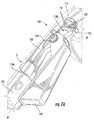
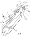
- Figures 7A and 7B illustrate trigger control 102, and portions thereof, as it is positioned within housing portion 104 and/or is protruding therefrom.
- Housing portion 104 can comprise a unitary housing or one or more cover portions (e.g., Figure 2 ) assembled via one or more mechanical fasteners M.
- Figure 7A illustrates a position of trigger control 102 and/or portions thereof in an OFF mode, such as when the machinery is not being driven or self-propelled.
- Figure 7B illustrates a position of trigger control 102 and/or portions thereof in an ON mode, such as when the machinery is driving in a forward direction and/or being self-propelled.
- trigger control 102 can comprise a first pressure sensitive member or a first lever 108 and a second pressure sensitive member or a second lever 110. At least a portion of first lever 108 can be connected or attached to a portion of second lever 110 via a biasing member 112.
- first lever 108 comprises a clutch lever adapted to engage the drive transmission by communicating with a controller (e.g., Figure 4 )
- second lever 110 comprises a change lever adapted to slow or stop rotation of one or more wheels via communicating signals to transmission via controller.
- biasing member 112 can comprise a spring or spring assembly.
- biasing member can be configured to bias first lever 108 such that it protrudes outward from housing portion 104 and towards the operator of the self-propelled machinery in the OFF mode.
- second lever 110 can be biased within housing portion 104 in the OFF mode, such that it does not protrude outward from and/or beyond an outer edge E of housing portion 104.
- Trigger control 102 can be adapted to engage, move, or otherwise physically communicate with a portion of at least one secondary potentiometer 114.
- Secondary potentiometer 114 can be adapted to reduce or stop speed set via a main potentiometer (e.g., via setting 100 ).
- secondary potentiometer 114 can be disposed over a portion of a gear 116.
- second lever 110 can comprise a first end 110A and a second end 110B.
- One or more teeth or splines 118 can be provided at second end 110B of second lever 110. Teeth or splines 118 can be adapted to engage and rotate one or more corresponding teeth or splines 120 of gear 116.
- FIG. 7A illustrates trigger control 102 in the OFF mode, which can transition into the ON mode by pressing first portion 108 of trigger control 102 towards housing 104 to engage the transmission and drive the machine.
- first lever 108 can move towards housing portion 104.
- pressing first lever 108 in direction D5 can cause a portion of first lever 108 to push against first end 110A of second lever 110.
- First lever 108 can be configured to eject a portion of second lever 110 from housing portion 104 upon application of pressure thereto, for example, and extend portions of second lever 110 beyond an outermost edge E of housing portion 104.
- first end 110A of second lever 110 can extend from housing portion 104 and second end 110B can remain within housing portion in the ON mode. That is, second lever 110 can remain hidden within housing portion 104 until clutch lever (e.g., first lever 108 ) is engaged via pressing or application of pressure thereto in direction D5.
- application of pressure to first lever 108 in direction D5 can engage the transmission and initiate the drive mode (e.g., from an OFF to an ON mode).
- the transmission can then match the speed set by the main potentiometer (e.g., via setting 100 ).
- Pressure can be applied to first end 110A of second lever 110 in a direction D6 to reduce the speed set by the main potentiometer. That is, application of pressure to second lever 110 in a direction D6 can rotate potentiometer 114 incrementally in directions R1 and/or R2 via rotation of gear 116.
- Second end 110B of second lever 110 can rotate gear 116 via engagement of corresponding splines 118 and 120.
- pressing second lever 110 in a direction D6 can rotate potentiometer 114 towards a zero position to lower the speed of the machinery, and ultimately terminate drive mode.
- approximately 15° rotation of second lever 110 can correspond to approximately 75° rotation of gear 116.
- application of pressure to change lever (e.g., second lever 110 ) in direction D6 rotates gear 116 counterclockwise a direction R1.
- application of pressure to clutch lever (e.g., first lever 108 ) in direction D5 rotates gear 116 clockwise a direction R2, and can increase speed back to the maximum speed set via a main potentiometer (e.g., via setting 100 ).
- control device 90 ( Figure 6 ) can comprise two trigger controls 102 disposed on two spaced apart and opposing gripping portions. Each trigger control 102 can operate as described in Figures 7A and 7B .
- trigger controls 102 can allow for one-handed operation or control over the self-propelled machinery. Such controls can be easily reached while steering the machinery, such that an operator is not required to lift a hand from gripping portion during steering.
- speed can be controlled via trigger controls 102 which do not require an operator to move his or her hands from gripping portions while steering. This can reduce operator fatigue and contribute to machinery that is more comfortable and use and easy to operate.
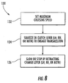
- Figure 8 is a flow chart illustrating an exemplary method, generally designated 130, for controlling aspects of self-propelled machinery via control devices and systems described hereinabove.
- the method can consist of or include a starting phase outlined via steps 72 and 74 previously described in Figure 5 .
- method 130 illustrates steps associated with a driving phase.
- an operator can set a maximum cruising speed using an electric control (e.g., setting 100, Figure 6 ) disposed on control device 90 ( Figure 6 ).
- a maximum cruising speed can be intuitively set via rotating a dial or knob (e.g. setting 100 ) clockwise and/or counterclockwise over control device 90 ( Figure 6 ).
- the maximum cruising speed can via electric signals communicated from a first (e.g., main) potentiometer to a control unit ( Figure 4 ).
- the operator can apply pressure via squeezing, pressing, and/or pushing in on portions of a clutch lever (e.g., first lever 108 ) of one or both trigger controls (e.g., 102, Figure 6-7B ).
- Pressing clutch lever (e.g., first lever 108 ) in a direction D5 ( Figure 7B ) can start or engage the electric transmission, which can initiate a drive mode (e.g., ON mode, Figure 7B ).
- Starting the transmission can transmit power to one or more wheels of the self-propelled machinery. The wheels can gradually propel the machinery to the maximum speed set via setting 100 ( Figure 6 ).
- an operator can use electric controls to slow or stop the machinery via electrically communicating the desire to slow or stop to the electric transmission.
- the one or more wheels can be slowed or stopped via retracting a change lever (e.g., second lever 110, Figure 7B ) within a housing portion (e.g., 104, Figure 7B ). That is, change lever can be squeezed, pressed, or retracted in a direction D6 ( Figure 7B ) towards the operator.
- An electric control unit ( Figure 4 ) can receive signals from trigger controls via one or more potentiometers ( 114, Figure 7B ) associated with each trigger control, and can incrementally increase or decrease speed a given amount upon interpretation of signals from potentiometer(s).
- aspects of the subject matter disclosed herein may provide one or more of the following beneficial technical effects: improved control of self-propelled machinery; easy speed change in self-propelled machinery; improved ease-of operation of self-propelled machinery; easy to turn machinery; easy to start machinery; intuitive controls; improved comfort during operation of self-propelled machinery; low operator fatigue; attractive size and/or shape of control device; ergonomic, easy to understand and comfortable controls; easy to manipulate trigger controls; easy, one-handed operation of machinery.
Landscapes
- Life Sciences & Earth Sciences (AREA)
- Environmental Sciences (AREA)
- Physics & Mathematics (AREA)
- General Physics & Mathematics (AREA)
- Engineering & Computer Science (AREA)
- Automation & Control Theory (AREA)
- Harvester Elements (AREA)
Claims (11)
- Selbstfahrende Maschine, welche aufweist:eine Steuervorrichtung (10), die einen Mittelabschnitt (14; 96) aufweist, der zwischen einem ersten Griffabschnitt (12A; 94A) und einem zweiten Griffabschnitt (12B; 94B) angeordnet ist; undzumindest eine druckempfindliche Triggersteuerung (36; 102), die über entweder dem ersten oder dem zweiten Griffabschnitt vorgesehen ist, wobei die Triggersteuerung (36; 102) konfiguriert ist, um eine Geschwindigkeit der selbstfahrenden Maschine durch Aktivierung eines Abschnitts eines ersten Potentiometers (38; 114) zu reduzieren, um ein von der Steuervorrichtung (10) getragenes elektrisches Signal zu verändern; undeinen drehbaren Einstellknopf (18; 100), der über dem Mittelabschnitt (14) vorgesehen ist, wobei der Einstellknopf (100) konfiguriert ist, um über ein zweites Potentiometer (32) eine maximale Geschwindigkeit einzustellen.
- Die Maschine von Anspruch 1, die ferner eine erste Triggersteuerung (36; 102), die über dem ersten Griffabschnitt (12A; 94A) vorgesehen ist, und eine zweite Triggersteuerung (36; 102), die über dem zweiten Griffabschnitt (12B; 94B) vorgesehen ist, aufweist.
- Die Maschine von Anspruch 1, die ferner einen Startdruckknopf (16; 98) aufweist, der über dem Mittelabschnitt vorgesehen ist.
- Die Maschine von Anspruch 1, wobei der erste Griffabschnitt (12A; 94A) in Bezug auf den zweiten Griffabschnitt (12B; 94B) gewinkelt ist.
- Die Maschine von Anspruch 1, wobei die Triggersteuerung (36; 102) mehrere Hebel aufweist.
- Die Maschine von Anspruch 5, wobei die mehreren Hebel einen ersten Hebel, der zum Einrücken eines elektrischen Getriebes (58) ausgelegt ist, und einen zweiten Hebel, der zum Verlangsamen oder Stoppen des elektrischen Getriebes ausgelegt ist, aufweisen.
- Die Maschine von Anspruch 1, wobei die Griffabschnitte (12A, B; 94A, B) und die Triggersteuerung (36; 102) dazu ausgelegt sind, von einer einzelnen Hand eines Bedieners ergriffen zu werden.
- Die Maschine von Anspruch 1, die ferner einen Schwenkbremshebel (40; 106) aufweist.
- Verfahren zum Steuern/Regeln einer selbstfahrenden Maschine, wobei das Verfahren aufweist:Bereitstellen einer Steuervorrichtung (10), die einen Mittelabschnitt (14; 96) aufweist, der zwischen einem ersten Griffabschnitt (12A; 94A) und einem zweiten Griffabschnitt (12B; 94B) angeordnet ist, wobei zumindest eine druckempfindliche Triggersteuerung an einem Griffabschnitt der Steuervorrichtung angeordnet ist; undAusüben von Druck auf die Triggersteuerung (36; 102) zum Einrücken eines Getriebes (58) durch Betätigen des Abschnitts eines ersten Potentiometers (38; 114);beim Einrücken des Getriebes (58), Ausüben eines anschließenden Drucks auf die Triggersteuerung (36, 102) zum Verlangsamen oder Stoppen des Getriebes, undEinstellen einer maximalen Geschwindigkeit durch Drehen eines über dem Mittelabschnitt (14) vorgesehenen Einstellknopfs (18; 100) über ein zweites Potentiometer (32).
- Das Verfahren von Anspruch 9, wobei das Bereitstellen der Steuervorrichtung (10) aufweist, eine erste Triggersteuerung (36; 102) über einem ersten Griffabschnitt (12A; 94A) vorzusehen und eine zweite Triggersteuerung (36; 102) über einem zweiten Griffabschnitt (12B; 94B) vorzusehen.
- Das Verfahren von Anspruch 9, wobei das Ausüben von Druck auf die Triggersteuerung (36; 102) aufweist, die Triggersteuerung zusammenzudrücken, während der Griffabschnitt (12A, B; 94A, B) ergriffen wird.
Applications Claiming Priority (1)
| Application Number | Priority Date | Filing Date | Title |
|---|---|---|---|
| US13/901,787 US9696749B2 (en) | 2013-05-24 | 2013-05-24 | Control devices, systems, and methods for self-propelled machinery |
Publications (2)
| Publication Number | Publication Date |
|---|---|
| EP2805597A1 EP2805597A1 (de) | 2014-11-26 |
| EP2805597B1 true EP2805597B1 (de) | 2016-04-06 |
Family
ID=50842045
Family Applications (1)
| Application Number | Title | Priority Date | Filing Date |
|---|---|---|---|
| EP14169273.1A Not-in-force EP2805597B1 (de) | 2013-05-24 | 2014-05-21 | Steuergeräte, Systeme und Verfahren für eine selbstangetriebene Maschine |
Country Status (2)
| Country | Link |
|---|---|
| US (1) | US9696749B2 (de) |
| EP (1) | EP2805597B1 (de) |
Families Citing this family (29)
| Publication number | Priority date | Publication date | Assignee | Title |
|---|---|---|---|---|
| US9696749B2 (en) | 2013-05-24 | 2017-07-04 | Honda Motor Co., Ltd. | Control devices, systems, and methods for self-propelled machinery |
| CN106171253B (zh) * | 2015-05-05 | 2020-06-23 | 南京德朔实业有限公司 | 割草机 |
| US9538699B1 (en) | 2015-07-06 | 2017-01-10 | Honda Motor Co., Ltd. | Adjustable ground speed and acceleration control devices, systems, and methods for walk-behind equipment |
| US9968031B2 (en) | 2015-07-06 | 2018-05-15 | Honda Motor Co., Ltd. | Adjustable ground speed and acceleration control devices, systems, and methods for walk-behind equipment |
| US11191210B2 (en) | 2016-03-17 | 2021-12-07 | Robert Bosch Gmbh | Manually guided garden device |
| CN105751891B (zh) * | 2016-03-29 | 2018-03-09 | 宁波市德霖机械有限公司 | 一种割草机的无极调速控制机构 |
| US10214869B1 (en) | 2016-04-28 | 2019-02-26 | Briggs & Stratton Corporation | Outdoor power equipment including electric wheel motors and controls |
| WO2017215604A1 (zh) * | 2016-06-14 | 2017-12-21 | 常州格力博有限公司 | 控制面板、自走开关装置及动力设备 |
| CA169824S (en) * | 2016-06-14 | 2017-03-20 | Changzhou Globe Co Ltd | Lawn mower handle assembly |
| JP2018085980A (ja) * | 2016-11-30 | 2018-06-07 | 本田技研工業株式会社 | 電動式作業機 |
| JP2018088832A (ja) * | 2016-11-30 | 2018-06-14 | 本田技研工業株式会社 | 作業機 |
| JP2018088833A (ja) * | 2016-11-30 | 2018-06-14 | 本田技研工業株式会社 | 電動式作業機 |
| EP3533312B1 (de) | 2017-05-02 | 2020-07-29 | Nanjing Chervon Industry Co., Ltd. | Handgeführte selbstfahrende maschine |
| US11690319B2 (en) | 2017-06-23 | 2023-07-04 | Techtronic Outdoor Products Technology Limited | Speed control assembly |
| US10588257B2 (en) | 2017-10-06 | 2020-03-17 | Black & Decker, Inc. | Pivoting handle assembly |
| US11178810B2 (en) | 2018-09-10 | 2021-11-23 | Cleo Preston Tutt, Jr. | Step and rail system to aid disabled operators of riding mowers |
| DE102018122366A1 (de) * | 2018-09-13 | 2020-03-19 | Alber Gmbh | Hilfsantriebsvorrichtung für einen Rollstuhl |
| US20200305341A1 (en) * | 2019-03-29 | 2020-10-01 | Deere & Company | Riding lawn equipment engine speed control module |
| CN112293035B (zh) | 2019-07-25 | 2026-03-27 | 南京泉峰科技有限公司 | 后走式自推工作机 |
| US20230037664A1 (en) * | 2019-07-25 | 2023-02-09 | Nanjing Chervon Industry Co., Ltd. | Rear-moving self-propelled working machine |
| US11528841B2 (en) | 2019-08-08 | 2022-12-20 | Honda Motor Co., Ltd. | Adjustable electric control handle for a lawn mower |
| WO2021071655A1 (en) | 2019-10-11 | 2021-04-15 | Ariens Company | Power source and control system for a lawn mower |
| CN112972909B (zh) * | 2019-12-13 | 2023-03-14 | 医科达(北京)医疗器械有限公司 | 用于放疗设备的控制器 |
| CN112057091B (zh) * | 2020-08-18 | 2021-08-03 | 北京唯迈医疗设备有限公司 | 一种调速手闸机构及其调速方法 |
| US11285986B1 (en) | 2020-11-06 | 2022-03-29 | Derrick F. Scott | Steering bar for lever controlled vehicle |
| US12365366B1 (en) * | 2021-06-14 | 2025-07-22 | Scythe Robotics, Inc. | Control interfaces for autonomous lawn mowers |
| US12069984B2 (en) | 2021-09-29 | 2024-08-27 | The Toro Company | Walk outdoor power equipment unit having handle mounted operational controls using compliant mechanisms |
| CN117999947B (zh) * | 2022-11-08 | 2026-04-21 | 南京泉峰科技有限公司 | 手推式动力工具 |
| US12610883B2 (en) | 2023-11-06 | 2026-04-28 | Honda Motor Co., Ltd. | Speed control system, self-propelled machine including same, and method for controlling travel speed of self-propelled machine |
Family Cites Families (81)
| Publication number | Priority date | Publication date | Assignee | Title |
|---|---|---|---|---|
| DE2217351A1 (de) | 1972-04-11 | 1973-10-31 | Wolf Geraete Gmbh | Elektromotorisch angetriebener rasenmaeher |
| US4213513A (en) | 1978-06-26 | 1980-07-22 | Mcgill Manufacturing Company, Inc. | Ignition control system with safety switches |
| US4221108A (en) | 1979-05-25 | 1980-09-09 | Owens Boyd L | Lawnmower safety control system |
| US4290256A (en) | 1979-12-10 | 1981-09-22 | Seifert Lester H | Single cable control system for lawn mower |
| US4309862A (en) | 1980-06-09 | 1982-01-12 | Capro, Inc. | Lawn mower and controls therefor |
| US4430848A (en) | 1981-09-28 | 1984-02-14 | Mcdonough Power Equipment, Division Of Fuqua Industries, Inc. | Double action manual control for walk-behind mower |
| US4696150A (en) | 1982-04-23 | 1987-09-29 | Geeck Iii Joseph S | Power mower with blade-brake clutch |
| US4476643A (en) * | 1983-03-08 | 1984-10-16 | Mtd Products Limited | Hand control system for motorized implements |
| GB2164233B (en) * | 1984-09-13 | 1987-10-07 | Honda Motor Co Ltd | Power grass mower |
| US4885903A (en) | 1988-07-27 | 1989-12-12 | Scag Dane T | Safety interlock for lawn mowers |
| GB8908633D0 (en) | 1989-04-17 | 1989-06-01 | Electrolux Northern | Safety control device |
| US4991382A (en) | 1989-08-30 | 1991-02-12 | Scag Power Equipment, Inc. | Lawn mower |
| US5020308A (en) | 1990-03-12 | 1991-06-04 | Deere & Company | Self-propelled steerable walk behind mower linkage |
| US5138824A (en) | 1990-05-25 | 1992-08-18 | Kubota Corporation | Safety system for a lawn mower |
| US5155985A (en) | 1990-10-16 | 1992-10-20 | Kubota Corporation | Working vehicle controllable by walking operator and having independently driven right and left ground wheels |
| CA2035003A1 (en) | 1990-12-03 | 1992-06-04 | Al Mitchell | Remote throttle control |
| US5195307A (en) | 1992-01-21 | 1993-03-23 | The Toro Company | Simplified blade brake clutch and propulsion control |
| US5203147A (en) | 1992-01-22 | 1993-04-20 | Ryobi Motor Products Corp. | Lawn mower activation switch |
| US5335487A (en) | 1992-03-06 | 1994-08-09 | Kubota Corporation | Engine speed control apparatus for a working vehicle |
| US5261214A (en) | 1992-08-21 | 1993-11-16 | The Toro Company | Lawn mower bail pivot stop and cable anchor |
| US5377774A (en) | 1993-02-04 | 1995-01-03 | Hoffco, Inc. | Variable speed drive system |
| US5353578A (en) | 1993-03-02 | 1994-10-11 | Fuqua Industries, Inc. | Drive system for lawn mowers |
| US5375674A (en) | 1993-04-13 | 1994-12-27 | Mtd Products Inc. | Operator control for lawn and garden vehicles |
| US5657669A (en) | 1995-07-31 | 1997-08-19 | Wescon Products Company | Lawnmower cable control apparatus |
| US5651241A (en) | 1995-10-11 | 1997-07-29 | Ransomes America Corporation | Walk-behind mower controls with dual function control bracket |
| US5692366A (en) * | 1995-12-14 | 1997-12-02 | Deere & Company | Walk-behind mower reverse belt tensioner |
| US6082083A (en) | 1998-09-18 | 2000-07-04 | The Toro Company | Ground speed control system |
| US6301864B1 (en) | 1999-07-22 | 2001-10-16 | Ariens Company | Interlock for lawnmower |
| ATE355731T1 (de) | 2000-06-26 | 2007-03-15 | Toro Co | Spindelmäher |
| CA2351863C (en) * | 2000-07-12 | 2005-08-09 | Honda Giken Kogyo Kabushiki Kaisha | Snow removing machine |
| JP4516189B2 (ja) | 2000-07-17 | 2010-08-04 | 本田技研工業株式会社 | 排雪板付き除雪機 |
| EP1333712B1 (de) | 2000-10-20 | 2006-06-07 | MTD Products Inc. | Vorrichtung und verfahren zum anlassen eines rasenmähermotors |
| US6805218B2 (en) * | 2000-10-30 | 2004-10-19 | Honda Giken Kogyo Kabushiki Kaisha | Motorized vehicle |
| JP4607382B2 (ja) | 2000-12-28 | 2011-01-05 | 本田技研工業株式会社 | 歩行型作業機 |
| CA2382731C (en) | 2001-04-20 | 2007-03-27 | Honda Giken Kogyo Kabushiki Kaisha | Walk behind self-propelled crawler snow plow |
| JP2002315416A (ja) | 2001-04-20 | 2002-10-29 | Honda Motor Co Ltd | 歩行型自走式作業機 |
| US6557331B2 (en) * | 2001-06-27 | 2003-05-06 | Exmark Manufacturing Company, Inc. | Operator control system for self-propelled vehicles |
| US6945133B2 (en) | 2001-08-23 | 2005-09-20 | Mtd Products Inc. | Speed control system for a power equipment vehicle |
| US6734647B2 (en) * | 2001-10-30 | 2004-05-11 | Honda Giken Kogyo Kabushiki Kaisha | Working machine |
| US6948299B2 (en) | 2002-11-22 | 2005-09-27 | Honda Motor Company, Ltd. | Hybrid power equipment |
| US7063177B1 (en) | 2003-07-18 | 2006-06-20 | Auburn Consolidated Industries, Inc. | Walk behind mower |
| JP3974570B2 (ja) | 2003-10-28 | 2007-09-12 | 本田技研工業株式会社 | 電動車両の走行制御方法 |
| US20050144919A1 (en) | 2004-01-05 | 2005-07-07 | Honda Motor Co., Ltd. | Variable speed transmission twist-grip throttle control apparatuses and methods for self-propelled mowing machine |
| US7318309B2 (en) | 2004-01-05 | 2008-01-15 | Honda Motor Co., Ltd | Variable speed transmission twist control apparatuses and methods for self-propelled mowing machine |
| JP4516324B2 (ja) * | 2004-02-04 | 2010-08-04 | 本田技研工業株式会社 | 電動車両 |
| JP4511867B2 (ja) | 2004-04-16 | 2010-07-28 | 本田技研工業株式会社 | 車両の操向ハンドル装置 |
| US7275615B2 (en) | 2004-05-21 | 2007-10-02 | Textron Inc. | Speed control system for walk behind powered equipment |
| US7850555B2 (en) | 2004-07-30 | 2010-12-14 | Honda Motor Co., Ltd. | Apparatuses and methods for controlling a variable speed transmission |
| US7540131B2 (en) | 2004-09-16 | 2009-06-02 | The Toro Company | Ground speed control system with hill assist, cruise control and lockout lever |
| JP4299221B2 (ja) * | 2004-10-29 | 2009-07-22 | 本田技研工業株式会社 | 作業機の舵取り装置 |
| US7730577B2 (en) | 2004-11-17 | 2010-06-08 | Nilfisk-Advance, Inc. | Control handle assembly |
| US7401425B2 (en) * | 2004-12-23 | 2008-07-22 | The Toro Company | Snowthrower wheel drive steering system |
| US7451865B2 (en) | 2005-01-18 | 2008-11-18 | Commercial Turf Products, Ltd. | Park brake and control lever interlock for ZTR vehicle |
| US7540102B2 (en) | 2005-03-02 | 2009-06-02 | Wisconsin Engineering, Cz S.R.O. | Snow blower apparatus |
| JP4528174B2 (ja) | 2005-03-18 | 2010-08-18 | 本田技研工業株式会社 | 歩行型作業機 |
| CA2553591C (en) | 2005-07-29 | 2014-05-20 | Honda Motor Co., Ltd. | Walk-behind self-propelled snow removing machine |
| CA2572595C (en) | 2006-01-26 | 2011-03-29 | Honda Motor Co., Ltd | Engine-driven work machine |
| US7938039B2 (en) | 2006-03-29 | 2011-05-10 | Wescon Products Company | Self locking cable control apparatus |
| JP4925723B2 (ja) | 2006-05-24 | 2012-05-09 | 本田技研工業株式会社 | 芝刈機の駆動操作機構 |
| JP4804225B2 (ja) | 2006-05-24 | 2011-11-02 | 本田技研工業株式会社 | 芝刈機の動力伝達制御機構 |
| US20080120955A1 (en) | 2006-10-17 | 2008-05-29 | Lucas Delbert R | Hybrid electric lawnmower |
| US7479754B2 (en) | 2006-10-17 | 2009-01-20 | Desa Ip Llc | Hybrid electric lawnmower |
| US8732896B2 (en) | 2006-10-17 | 2014-05-27 | Mtd Products Inc | Hybrid electric cleaning device |
| GB0622148D0 (en) | 2006-11-07 | 2006-12-20 | Arpino Mario P | Walk-with apparatus |
| GB2452031A (en) | 2007-08-15 | 2009-02-25 | Husqvarna Ab | Lawnmower lever flexibly or pivotably anchored at one end, attached to a switch pull cord at the other end. |
| US7543430B2 (en) | 2007-09-10 | 2009-06-09 | Honda Motor Co., Ltd. | Button type blade brake clutch control |
| US7543429B2 (en) | 2007-10-26 | 2009-06-09 | Honda Motor Co., Ltd. | Variable speed transmission adjustable twist control apparatuses and methods for self-propelled mowing machine |
| US7971695B2 (en) * | 2007-12-20 | 2011-07-05 | Honda Motor Co., Ltd. | Independent variable drive assemblies for wheels on a snowblower and related methods |
| US20090223475A1 (en) | 2008-03-10 | 2009-09-10 | Grant Thomas Wilson | Implement With Two Hand Interlock |
| US20090223191A1 (en) * | 2008-03-10 | 2009-09-10 | Grant Thomas Wilson | Mechanical Interlock for a Control Member |
| US7849943B1 (en) | 2008-04-17 | 2010-12-14 | Norm Ragland | Towing device |
| EP2302994A1 (de) | 2008-06-30 | 2011-04-06 | Husqvarna AB | Antriebshandbetätigungssystem für einen rasenmäher |
| US7698881B2 (en) | 2008-09-12 | 2010-04-20 | Briggs And Stratton Corporation | Walk-behind mower control system and method |
| US7762050B1 (en) | 2009-03-11 | 2010-07-27 | Honda Motor Co., Ltd. | Bail-free machine control devices and methods |
| US8312946B2 (en) | 2009-07-02 | 2012-11-20 | Husqvarna Consumer Outdoor Products N.A., Inc. | Trigger controller |
| US20110126502A1 (en) | 2009-11-30 | 2011-06-02 | Briggs & Stratton Corporation | Driving speed control for power equipment |
| US8381885B2 (en) | 2009-12-14 | 2013-02-26 | Kohler Co. | Brake system and lawn mower implementing the same |
| US8079433B2 (en) | 2010-02-16 | 2011-12-20 | Deere & Company | Retractable line guidance for self-propelled machines |
| WO2011131031A1 (zh) | 2010-04-21 | 2011-10-27 | 苏州宝时得电动工具有限公司 | 割草机和控制割草机自驱操作的控制方法 |
| US8573368B2 (en) | 2011-03-22 | 2013-11-05 | The Toro Company | Motor driven parking brake actuator system for mower |
| US9696749B2 (en) | 2013-05-24 | 2017-07-04 | Honda Motor Co., Ltd. | Control devices, systems, and methods for self-propelled machinery |
-
2013
- 2013-05-24 US US13/901,787 patent/US9696749B2/en not_active Expired - Fee Related
-
2014
- 2014-05-21 EP EP14169273.1A patent/EP2805597B1/de not_active Not-in-force
Also Published As
| Publication number | Publication date |
|---|---|
| US20140345416A1 (en) | 2014-11-27 |
| EP2805597A1 (de) | 2014-11-26 |
| US9696749B2 (en) | 2017-07-04 |
Similar Documents
| Publication | Publication Date | Title |
|---|---|---|
| EP2805597B1 (de) | Steuergeräte, Systeme und Verfahren für eine selbstangetriebene Maschine | |
| CN105605210B (zh) | 步行式作业机的变速控制系统及该作业机的速度变化方法 | |
| US7178322B2 (en) | Apparatuses and methods for controlling self-propelled machines | |
| US9538699B1 (en) | Adjustable ground speed and acceleration control devices, systems, and methods for walk-behind equipment | |
| EP1864565B1 (de) | Vorrichtung und Verfahren zur Steuerung einer Übertragungsdrehung mit variabler Drehzahl für eine selbstangetriebene Mähmaschine | |
| KR100687770B1 (ko) | 워크-비하인드 타입 구동 장치의 속도 제어 시스템 | |
| US9616893B2 (en) | Automatic turn-sensing ground speed reduction systems and related methods for walk-behind machines | |
| US20050144919A1 (en) | Variable speed transmission twist-grip throttle control apparatuses and methods for self-propelled mowing machine | |
| US20130046448A1 (en) | Lawn mower and method for controlling self-driving operations of the lawn mower | |
| CN201752182U (zh) | 自驱割草机 | |
| CN102232333A (zh) | 自驱割草机 | |
| US7543429B2 (en) | Variable speed transmission adjustable twist control apparatuses and methods for self-propelled mowing machine | |
| WO2018201525A1 (zh) | 后走式自推进机器 | |
| US20140102068A1 (en) | Speed control device for lawnmower | |
| US9338940B2 (en) | Drive systems and methods for implementing engine stall protection in a self-propelled machine | |
| CN202818965U (zh) | 割灌机 | |
| CN111615915B (zh) | 操作装置、园艺加工机和用于运行园艺加工机的方法 | |
| CN114365616A (zh) | 手推式电动工具 | |
| US20100004093A1 (en) | Automatic engine speed adjustment | |
| CN217905178U (zh) | 手推式动力工具 | |
| CN101098621B (zh) | 包括驱动装置以及起动和/或断开制动装置的工作器具 | |
| CN218483252U (zh) | 动力工具手柄结构以及动力工具 | |
| US12610883B2 (en) | Speed control system, self-propelled machine including same, and method for controlling travel speed of self-propelled machine | |
| US20190075725A1 (en) | Propulsion control system and turf maintenance vehicle incorporating same | |
| CN115039562A (zh) | 手推式动力工具 |
Legal Events
| Date | Code | Title | Description |
|---|---|---|---|
| PUAI | Public reference made under article 153(3) epc to a published international application that has entered the european phase |
Free format text: ORIGINAL CODE: 0009012 |
|
| 17P | Request for examination filed |
Effective date: 20140521 |
|
| AK | Designated contracting states |
Kind code of ref document: A1 Designated state(s): AL AT BE BG CH CY CZ DE DK EE ES FI FR GB GR HR HU IE IS IT LI LT LU LV MC MK MT NL NO PL PT RO RS SE SI SK SM TR |
|
| AX | Request for extension of the european patent |
Extension state: BA ME |
|
| GRAP | Despatch of communication of intention to grant a patent |
Free format text: ORIGINAL CODE: EPIDOSNIGR1 |
|
| RIC1 | Information provided on ipc code assigned before grant |
Ipc: A01D 34/47 20060101AFI20150916BHEP Ipc: A01D 34/68 20060101ALI20150916BHEP |
|
| INTG | Intention to grant announced |
Effective date: 20151015 |
|
| GRAS | Grant fee paid |
Free format text: ORIGINAL CODE: EPIDOSNIGR3 |
|
| GRAA | (expected) grant |
Free format text: ORIGINAL CODE: 0009210 |
|
| AK | Designated contracting states |
Kind code of ref document: B1 Designated state(s): AL AT BE BG CH CY CZ DE DK EE ES FI FR GB GR HR HU IE IS IT LI LT LU LV MC MK MT NL NO PL PT RO RS SE SI SK SM TR |
|
| REG | Reference to a national code |
Ref country code: GB Ref legal event code: FG4D |
|
| REG | Reference to a national code |
Ref country code: AT Ref legal event code: REF Ref document number: 786646 Country of ref document: AT Kind code of ref document: T Effective date: 20160415 Ref country code: CH Ref legal event code: EP |
|
| REG | Reference to a national code |
Ref country code: IE Ref legal event code: FG4D |
|
| REG | Reference to a national code |
Ref country code: DE Ref legal event code: R096 Ref document number: 602014001354 Country of ref document: DE |
|
| REG | Reference to a national code |
Ref country code: FR Ref legal event code: PLFP Year of fee payment: 3 |
|
| REG | Reference to a national code |
Ref country code: SE Ref legal event code: TRGR |
|
| REG | Reference to a national code |
Ref country code: LT Ref legal event code: MG4D Ref country code: NL Ref legal event code: MP Effective date: 20160406 |
|
| REG | Reference to a national code |
Ref country code: AT Ref legal event code: MK05 Ref document number: 786646 Country of ref document: AT Kind code of ref document: T Effective date: 20160406 |
|
| PG25 | Lapsed in a contracting state [announced via postgrant information from national office to epo] |
Ref country code: BE Free format text: LAPSE BECAUSE OF NON-PAYMENT OF DUE FEES Effective date: 20160531 |
|
| PG25 | Lapsed in a contracting state [announced via postgrant information from national office to epo] |
Ref country code: NL Free format text: LAPSE BECAUSE OF FAILURE TO SUBMIT A TRANSLATION OF THE DESCRIPTION OR TO PAY THE FEE WITHIN THE PRESCRIBED TIME-LIMIT Effective date: 20160406 |
|
| PG25 | Lapsed in a contracting state [announced via postgrant information from national office to epo] |
Ref country code: IS Free format text: LAPSE BECAUSE OF FAILURE TO SUBMIT A TRANSLATION OF THE DESCRIPTION OR TO PAY THE FEE WITHIN THE PRESCRIBED TIME-LIMIT Effective date: 20160806 Ref country code: NO Free format text: LAPSE BECAUSE OF FAILURE TO SUBMIT A TRANSLATION OF THE DESCRIPTION OR TO PAY THE FEE WITHIN THE PRESCRIBED TIME-LIMIT Effective date: 20160706 Ref country code: PL Free format text: LAPSE BECAUSE OF FAILURE TO SUBMIT A TRANSLATION OF THE DESCRIPTION OR TO PAY THE FEE WITHIN THE PRESCRIBED TIME-LIMIT Effective date: 20160406 Ref country code: LT Free format text: LAPSE BECAUSE OF FAILURE TO SUBMIT A TRANSLATION OF THE DESCRIPTION OR TO PAY THE FEE WITHIN THE PRESCRIBED TIME-LIMIT Effective date: 20160406 Ref country code: FI Free format text: LAPSE BECAUSE OF FAILURE TO SUBMIT A TRANSLATION OF THE DESCRIPTION OR TO PAY THE FEE WITHIN THE PRESCRIBED TIME-LIMIT Effective date: 20160406 |
|
| PG25 | Lapsed in a contracting state [announced via postgrant information from national office to epo] |
Ref country code: GR Free format text: LAPSE BECAUSE OF FAILURE TO SUBMIT A TRANSLATION OF THE DESCRIPTION OR TO PAY THE FEE WITHIN THE PRESCRIBED TIME-LIMIT Effective date: 20160707 Ref country code: HR Free format text: LAPSE BECAUSE OF FAILURE TO SUBMIT A TRANSLATION OF THE DESCRIPTION OR TO PAY THE FEE WITHIN THE PRESCRIBED TIME-LIMIT Effective date: 20160406 Ref country code: AT Free format text: LAPSE BECAUSE OF FAILURE TO SUBMIT A TRANSLATION OF THE DESCRIPTION OR TO PAY THE FEE WITHIN THE PRESCRIBED TIME-LIMIT Effective date: 20160406 Ref country code: PT Free format text: LAPSE BECAUSE OF FAILURE TO SUBMIT A TRANSLATION OF THE DESCRIPTION OR TO PAY THE FEE WITHIN THE PRESCRIBED TIME-LIMIT Effective date: 20160808 Ref country code: RS Free format text: LAPSE BECAUSE OF FAILURE TO SUBMIT A TRANSLATION OF THE DESCRIPTION OR TO PAY THE FEE WITHIN THE PRESCRIBED TIME-LIMIT Effective date: 20160406 Ref country code: LV Free format text: LAPSE BECAUSE OF FAILURE TO SUBMIT A TRANSLATION OF THE DESCRIPTION OR TO PAY THE FEE WITHIN THE PRESCRIBED TIME-LIMIT Effective date: 20160406 Ref country code: ES Free format text: LAPSE BECAUSE OF FAILURE TO SUBMIT A TRANSLATION OF THE DESCRIPTION OR TO PAY THE FEE WITHIN THE PRESCRIBED TIME-LIMIT Effective date: 20160406 |
|
| PG25 | Lapsed in a contracting state [announced via postgrant information from national office to epo] |
Ref country code: IT Free format text: LAPSE BECAUSE OF FAILURE TO SUBMIT A TRANSLATION OF THE DESCRIPTION OR TO PAY THE FEE WITHIN THE PRESCRIBED TIME-LIMIT Effective date: 20160406 Ref country code: BE Free format text: LAPSE BECAUSE OF FAILURE TO SUBMIT A TRANSLATION OF THE DESCRIPTION OR TO PAY THE FEE WITHIN THE PRESCRIBED TIME-LIMIT Effective date: 20160406 |
|
| REG | Reference to a national code |
Ref country code: DE Ref legal event code: R097 Ref document number: 602014001354 Country of ref document: DE |
|
| PG25 | Lapsed in a contracting state [announced via postgrant information from national office to epo] |
Ref country code: RO Free format text: LAPSE BECAUSE OF FAILURE TO SUBMIT A TRANSLATION OF THE DESCRIPTION OR TO PAY THE FEE WITHIN THE PRESCRIBED TIME-LIMIT Effective date: 20160406 Ref country code: DK Free format text: LAPSE BECAUSE OF FAILURE TO SUBMIT A TRANSLATION OF THE DESCRIPTION OR TO PAY THE FEE WITHIN THE PRESCRIBED TIME-LIMIT Effective date: 20160406 Ref country code: MC Free format text: LAPSE BECAUSE OF FAILURE TO SUBMIT A TRANSLATION OF THE DESCRIPTION OR TO PAY THE FEE WITHIN THE PRESCRIBED TIME-LIMIT Effective date: 20160406 Ref country code: CZ Free format text: LAPSE BECAUSE OF FAILURE TO SUBMIT A TRANSLATION OF THE DESCRIPTION OR TO PAY THE FEE WITHIN THE PRESCRIBED TIME-LIMIT Effective date: 20160406 Ref country code: EE Free format text: LAPSE BECAUSE OF FAILURE TO SUBMIT A TRANSLATION OF THE DESCRIPTION OR TO PAY THE FEE WITHIN THE PRESCRIBED TIME-LIMIT Effective date: 20160406 Ref country code: SK Free format text: LAPSE BECAUSE OF FAILURE TO SUBMIT A TRANSLATION OF THE DESCRIPTION OR TO PAY THE FEE WITHIN THE PRESCRIBED TIME-LIMIT Effective date: 20160406 |
|
| PLBE | No opposition filed within time limit |
Free format text: ORIGINAL CODE: 0009261 |
|
| STAA | Information on the status of an ep patent application or granted ep patent |
Free format text: STATUS: NO OPPOSITION FILED WITHIN TIME LIMIT |
|
| REG | Reference to a national code |
Ref country code: IE Ref legal event code: MM4A |
|
| PG25 | Lapsed in a contracting state [announced via postgrant information from national office to epo] |
Ref country code: SM Free format text: LAPSE BECAUSE OF FAILURE TO SUBMIT A TRANSLATION OF THE DESCRIPTION OR TO PAY THE FEE WITHIN THE PRESCRIBED TIME-LIMIT Effective date: 20160406 |
|
| 26N | No opposition filed |
Effective date: 20170110 |
|
| REG | Reference to a national code |
Ref country code: FR Ref legal event code: PLFP Year of fee payment: 4 |
|
| PG25 | Lapsed in a contracting state [announced via postgrant information from national office to epo] |
Ref country code: SI Free format text: LAPSE BECAUSE OF FAILURE TO SUBMIT A TRANSLATION OF THE DESCRIPTION OR TO PAY THE FEE WITHIN THE PRESCRIBED TIME-LIMIT Effective date: 20160406 Ref country code: IE Free format text: LAPSE BECAUSE OF NON-PAYMENT OF DUE FEES Effective date: 20160521 |
|
| REG | Reference to a national code |
Ref country code: CH Ref legal event code: PL |
|
| PG25 | Lapsed in a contracting state [announced via postgrant information from national office to epo] |
Ref country code: CH Free format text: LAPSE BECAUSE OF NON-PAYMENT OF DUE FEES Effective date: 20170531 Ref country code: LI Free format text: LAPSE BECAUSE OF NON-PAYMENT OF DUE FEES Effective date: 20170531 |
|
| REG | Reference to a national code |
Ref country code: FR Ref legal event code: PLFP Year of fee payment: 5 |
|
| PG25 | Lapsed in a contracting state [announced via postgrant information from national office to epo] |
Ref country code: HU Free format text: LAPSE BECAUSE OF FAILURE TO SUBMIT A TRANSLATION OF THE DESCRIPTION OR TO PAY THE FEE WITHIN THE PRESCRIBED TIME-LIMIT; INVALID AB INITIO Effective date: 20140521 |
|
| PG25 | Lapsed in a contracting state [announced via postgrant information from national office to epo] |
Ref country code: MT Free format text: LAPSE BECAUSE OF NON-PAYMENT OF DUE FEES Effective date: 20160531 Ref country code: CY Free format text: LAPSE BECAUSE OF FAILURE TO SUBMIT A TRANSLATION OF THE DESCRIPTION OR TO PAY THE FEE WITHIN THE PRESCRIBED TIME-LIMIT Effective date: 20160406 Ref country code: LU Free format text: LAPSE BECAUSE OF NON-PAYMENT OF DUE FEES Effective date: 20160521 Ref country code: MK Free format text: LAPSE BECAUSE OF FAILURE TO SUBMIT A TRANSLATION OF THE DESCRIPTION OR TO PAY THE FEE WITHIN THE PRESCRIBED TIME-LIMIT Effective date: 20160406 |
|
| PG25 | Lapsed in a contracting state [announced via postgrant information from national office to epo] |
Ref country code: BG Free format text: LAPSE BECAUSE OF FAILURE TO SUBMIT A TRANSLATION OF THE DESCRIPTION OR TO PAY THE FEE WITHIN THE PRESCRIBED TIME-LIMIT Effective date: 20160406 |
|
| PG25 | Lapsed in a contracting state [announced via postgrant information from national office to epo] |
Ref country code: AL Free format text: LAPSE BECAUSE OF FAILURE TO SUBMIT A TRANSLATION OF THE DESCRIPTION OR TO PAY THE FEE WITHIN THE PRESCRIBED TIME-LIMIT Effective date: 20160406 Ref country code: TR Free format text: LAPSE BECAUSE OF FAILURE TO SUBMIT A TRANSLATION OF THE DESCRIPTION OR TO PAY THE FEE WITHIN THE PRESCRIBED TIME-LIMIT Effective date: 20160406 |
|
| GBPC | Gb: european patent ceased through non-payment of renewal fee |
Effective date: 20180521 |
|
| PG25 | Lapsed in a contracting state [announced via postgrant information from national office to epo] |
Ref country code: GB Free format text: LAPSE BECAUSE OF NON-PAYMENT OF DUE FEES Effective date: 20180521 |
|
| PGFP | Annual fee paid to national office [announced via postgrant information from national office to epo] |
Ref country code: FR Payment date: 20200414 Year of fee payment: 7 |
|
| PGFP | Annual fee paid to national office [announced via postgrant information from national office to epo] |
Ref country code: SE Payment date: 20200512 Year of fee payment: 7 |
|
| PGFP | Annual fee paid to national office [announced via postgrant information from national office to epo] |
Ref country code: DE Payment date: 20210427 Year of fee payment: 8 |
|
| REG | Reference to a national code |
Ref country code: SE Ref legal event code: EUG |
|
| PG25 | Lapsed in a contracting state [announced via postgrant information from national office to epo] |
Ref country code: SE Free format text: LAPSE BECAUSE OF NON-PAYMENT OF DUE FEES Effective date: 20210522 |
|
| PG25 | Lapsed in a contracting state [announced via postgrant information from national office to epo] |
Ref country code: FR Free format text: LAPSE BECAUSE OF NON-PAYMENT OF DUE FEES Effective date: 20210531 |
|
| REG | Reference to a national code |
Ref country code: DE Ref legal event code: R119 Ref document number: 602014001354 Country of ref document: DE |
|
| PG25 | Lapsed in a contracting state [announced via postgrant information from national office to epo] |
Ref country code: DE Free format text: LAPSE BECAUSE OF NON-PAYMENT OF DUE FEES Effective date: 20221201 |