EP2806074A2 - Dispositif de fixation et distribution pour la montage dans une cuvette et méthode pour la production dudit dispositif de distribution - Google Patents
Dispositif de fixation et distribution pour la montage dans une cuvette et méthode pour la production dudit dispositif de distribution Download PDFInfo
- Publication number
- EP2806074A2 EP2806074A2 EP14162009.6A EP14162009A EP2806074A2 EP 2806074 A2 EP2806074 A2 EP 2806074A2 EP 14162009 A EP14162009 A EP 14162009A EP 2806074 A2 EP2806074 A2 EP 2806074A2
- Authority
- EP
- European Patent Office
- Prior art keywords
- holding device
- receiving area
- toilet bowl
- front shell
- rear shell
- Prior art date
- Legal status (The legal status is an assumption and is not a legal conclusion. Google has not performed a legal analysis and makes no representation as to the accuracy of the status listed.)
- Withdrawn
Links
Images



Classifications
-
- E—FIXED CONSTRUCTIONS
- E03—WATER SUPPLY; SEWERAGE
- E03D—WATER-CLOSETS OR URINALS WITH FLUSHING DEVICES; FLUSHING VALVES THEREFOR
- E03D9/00—Sanitary or other accessories for lavatories ; Devices for cleaning or disinfecting the toilet room or the toilet bowl; Devices for eliminating smells
- E03D9/02—Devices adding a disinfecting, deodorising, or cleaning agent to the water while flushing
- E03D9/022—Devices adding a disinfecting, deodorising, or cleaning agent to the water while flushing consisting of solid substances introduced in the bowl or the supply line
-
- E—FIXED CONSTRUCTIONS
- E03—WATER SUPPLY; SEWERAGE
- E03D—WATER-CLOSETS OR URINALS WITH FLUSHING DEVICES; FLUSHING VALVES THEREFOR
- E03D9/00—Sanitary or other accessories for lavatories ; Devices for cleaning or disinfecting the toilet room or the toilet bowl; Devices for eliminating smells
- E03D9/02—Devices adding a disinfecting, deodorising, or cleaning agent to the water while flushing
- E03D9/03—Devices adding a disinfecting, deodorising, or cleaning agent to the water while flushing consisting of a separate container with an outlet through which the agent is introduced into the flushing water, e.g. by suction ; Devices for agents in direct contact with flushing water
- E03D9/032—Devices connected to or dispensing into the bowl
-
- E—FIXED CONSTRUCTIONS
- E03—WATER SUPPLY; SEWERAGE
- E03D—WATER-CLOSETS OR URINALS WITH FLUSHING DEVICES; FLUSHING VALVES THEREFOR
- E03D9/00—Sanitary or other accessories for lavatories ; Devices for cleaning or disinfecting the toilet room or the toilet bowl; Devices for eliminating smells
- E03D9/02—Devices adding a disinfecting, deodorising, or cleaning agent to the water while flushing
- E03D2009/024—Devices adding a disinfecting, deodorising, or cleaning agent to the water while flushing using a solid substance
-
- E—FIXED CONSTRUCTIONS
- E03—WATER SUPPLY; SEWERAGE
- E03D—WATER-CLOSETS OR URINALS WITH FLUSHING DEVICES; FLUSHING VALVES THEREFOR
- E03D9/00—Sanitary or other accessories for lavatories ; Devices for cleaning or disinfecting the toilet room or the toilet bowl; Devices for eliminating smells
- E03D9/02—Devices adding a disinfecting, deodorising, or cleaning agent to the water while flushing
- E03D2009/026—Devices adding a disinfecting, deodorising, or cleaning agent to the water while flushing using a gel-form substance
Definitions
- the present invention relates to a holding device and a flushing device for mounting in a toilet bowl. It also relates to a manufacturing method for producing such a flushing device.
- Such holding devices also known as “toilet bowls", are used to hold chemical compositions which are usually released during a rinsing process at least partially into the rinsing water of the toilet bowl.
- Such compositions are referred to hereinafter as “detergent units”.
- the holding devices - usually this is in addition to holding detergent units - also hold other chemical compositions, in particular so-called fragrance units, so of fragrance compositions, at least less in the rinse water, but rather (often preferably exclusively) to the ambient air of the toilet bowl, So in a toilet room, to be delivered.
- Cleaning agent of a detergent unit is usually added to the rinse water as needed, i. H. in a rinsing process, while fragrance of a fragrance unit is also released continuously to the ambient air.
- a metering device in which a water-activatable perfume and / or cleaning and / or disinfecting agent is contained in a carrier which consists of a filled with a filler tube, so that in the interior of the tube an open-pore volume for receiving the agent forms.
- This tube is inserted into a receiving part of the container, which is flushed together with the other areas of the rinse water, so that ultimately the agent is discharged into the entire area within the container and gradually with the rinse water.
- this may have on the inside water steering organs in the form of perforated partitions which extend transversely throughout the housing.
- EP 1 797 251 B1 such a combined holding device.
- a front shell and a rear shell which can be connected together and hung together using a suspension in the edge of a toilet bowl.
- the interior of the holding device is subdivided into a plurality of separate receiving areas, namely into a first receiving area for receiving a cleaning agent unit, a second receiving area for receiving a fragrance unit and a third receiving area, again for receiving a cleaning agent unit.
- This division into contiguous receiving areas is realized by folding the front shell and the rear shell together, wherein in each case complementarily arranged webs in the front and the rear shell provide for a subdivision into the three receiving areas.
- the object of the invention presented here is to provide an improved alternative embodiment of a holding device with at least one first receiving area for receiving a cleaning agent unit and a second receiving area for receiving a fragrance unit.
- This object is achieved by a holding device according to claim 1 and by a manufacturing method according to claim 13.
- the second receiving region is formed as part of the rear shell. It includes a bounding box that is dimensioned to be closed when closed Holding device circumferentially bridges around the second receiving area a distance from the rear shell inside to the front shell inside. This is preferably realized in such a way that the boundary frame protrudes from the rear shell from the rear shell inside in a direction away from the rear shell outer side, ie projects beyond all other region of the rear shell in this direction.
- the holding device is then referred to, when the front and rear shell are connected to each other via the connecting elements (preferably via all connecting elements) or if the rear shell inside assigns to the front shell inside and along with a designated intended two-dimensional , preferably circumferential, contact line is connected.
- This can be done for example by folding the front shell on the rear shell (or the rear shell on the front shell) along a bending axis of a hinge (for example, a film hinge), wherein the hinge is designed as a connecting element and the front shell and the rear shell, for example, permanently interconnected.
- the second receiving area can be raised further upwards compared to the cited prior art, ie. H. with respect to a closed state of the holding device in the direction of the front shell outer side practically to the extension of the front shell inside with a fragrance unit, in particular with a fragrance gel, filled or equipped.
- the surface of this perfume unit is thus closer to the front shell outside, which also defines the front outside of the holding device (with respect to a proper suspension of the holding device in a toilet bowl). This significantly improves the fragrance delivery from the second receiving area.
- the second receiving area is thus formed as part of the rear shell.
- This has the advantage that it can be filled or filled with the fragrance unit (s) together with the first receiving area virtually at the same time (or in a loading or filling operation) (during the first receiving area with the detergent unit (s) ) is filled / filled), namely from the same side, ie in the direction of the rear shell inside.
- assembly and filling also in the claims, are used synonymously.
- the second receiving area is completely formed in the present case as part of the rear shell, and not, as in the above-mentioned prior art, only partially (since there form the complementary holding webs of the front shell part of the second receiving area).
- the bridging of the rear shell inside to the front shell inside takes place without exception only by a part of the rear shell, namely the limiting frame of the second receiving area, as Part of the rear shell is formed.
- Such a limiting frame may be formed as a separate component, which is firmly connected to the rear shell, but preferably it is formed as an integral part of the rear shell, so it can be made in one piece with the rear shell, such as in a thermoforming or injection molding.
- the advantageously peripheral boundary frame in the interior of the holding device ensures during operation of the holding device, d. H. in their state equipped with the fragrance unit (s) and detergent unit (s), and also reliable in keeping the fragrance unit (s) and the detergent unit (s) not only spatially but also materially separated from each other, in particular so that flushing water of the toilet bowl added with cleaning agent from the detergent unit (s) does not pass from the first receiving area into the second receiving area and thus into the region of the fragrance unit (s) where it hampers the functionality (ie the fragrance delivery) of the latter could.
- the invention also includes a flushing device for mounting in a toilet bowl with a holding device according to the invention and a number of detergent units in the first receiving area and / or a third receiving area of the holding device.
- a flushing device thus forms the holding device according to the invention to the effect that it is equipped with at least one detergent unit.
- the invention also comprises a flushing device for attachment in a toilet bowl, in particular the flushing device described above, with a holding device according to the invention and a number of perfume units in the second receiving region of the holding device.
- the holding device also comprises a passage window in a region of the front shell, when connected the front shell and the rear shell is positioned opposite the second receiving region, wherein the passage window is formed as an engagement and / or inspection window.
- This engagement or inspection window is thus not designed as a simple small slot, but rather large enough to a user with the holding device closed (ie, when the front and rear shell are connected to each other via all fasteners or if the rear shell inside to the front shells Assigns inside and connected to this along a designated intended two-dimensional contact line) access or effortless insight into the interior, in particular in the second receiving area (and more preferably exclusively in there) to allow.
- a "effortless" insight or intervention is in particular defined by the fact that a user with normal vision can recognize the contents of the second receiving area even if he looks at the front shell outside at a distance of 500 mm, without the holding device exactly in to twist a certain position.
- the passage window is therefore in comparison to a considerable (at least three times, preferably five times, more preferably eight times) enlarged in area passage.
- the passage window allows visual inspection.
- the second receiving area can also be (re) equipped with a fragrance unit through the passage window without the holding device having to be opened for this purpose.
- sizing the passage window allows fragrance delivery from the fragrance unit, and fourthly, it also facilitates rinsing the surface of the fragrance unit over a large area and relatively evenly with the rinse water without rinse water remaining in the second containment area for an extended period of time could reduce the fragrance delivery.
- the passage window is particularly preferably dimensioned so that it allows access to the second receiving area over an entire outer surface of the fragrance unit in the direction of the front shell, so that the second receiving area forms a cavity open to the front shell outside in the front shell.
- the second receiving area although arranged in the rear shell (for example when viewed from an injection molding point of view), is formed as an integral part of the front shell or the front side of the holding or flushing device when the holding or flushing device according to the invention is closed Access to the second receiving area is namely possible in this closed state exclusively from the front shell outside.
- the passage window thus extends (in particular in terms of area) substantially along the entire projected outer surface of the second receiving area or a perfume unit held in this second receiving area.
- "Essentially” in this context means that the two areas of the transmission window and the second reception area and / or the perfume unit contained therein are not more than 30%, preferably not more than 20%, more preferably not more than 10 % differ from each other. With such a slight deviation, the area of the passage window is preferably the smaller of the two compared surfaces, so that it is ensured that the front shell limits the second receiving area such that it uses the front shell and the delimiting frame with respect to the first receiving area and possibly further Recording areas (see below) is separated.
- the front shell inside has a recess in the direction of the front shell outer side in a contact region in which the limiting frame of the second receiving portion is in contact with the front shell inside with the holding device closed.
- the delimiting frame then engages in this depression in the contact region, so that at least in regions there is a positive connection between the delimiting frame and the front shell inside in the region of the depression.
- the recess is formed circumferentially, ie it describes a closed line.
- the position of the recess over the entire course of the delimiting frame corresponds with its position, so that the delimiting frame is completely embedded in the holding device closed in the recess.
- the depression preferably runs along an edge of the above-mentioned passage window and is delimited by the latter preferably inwards (ie towards the passage window). This means that the bounding box is embedded in the well and through the pass-through window access to the second receiving area along the entire outer surface of the fragrance unit is possible.
- the rear shell inside in the region of the second receiving area in comparison to a plane of the rear shell inside in the region of the first receiving area - and possibly further receiving areas (see below) - (for example, podium-like) increases.
- This increase goes in the direction of the front shell with the holding device closed.
- an outer surface of the fragrance unit it can be made possible for an outer surface of the fragrance unit to be arranged closer in the direction of the outer shells outside (with the holding device closed) or (if the holding device is mounted in the toilet bowl as intended) of the central region of the toilet bowl. It may then, for example (and preferably), be arranged substantially coplanar with an outer surface of an unused detergent unit in the direction of the central area of the toilet bowl.
- the outer surface of the fragrance unit in the direction of the central portion of the toilet bowl (when suspending hanging device) in an unused state of the perfume unit has a maximum distance of 4 mm to the front shell outside.
- this has an overall extension or height in the direction from the rear shell to the front shell of at least 8 mm, preferably 10 mm, particularly preferably 12 mm.
- the fragrance gel extends along the entire extension of the delimiting frame in this direction over at least 2 mm, preferably 4 mm, particularly preferably 5 mm.
- This total extension of the delimiting frame preferably reaches at least 3 mm, preferably 5 mm, particularly preferably 6 mm.
- the production method according to the invention is preferably developed in such a way that the second receiving area of the holding device is filled with a fragrance gel, preferably so that an outer surface of the fragrance gel has a maximum distance of 4 mm to the front shell outside with the holding device (1) closed, particularly preferably such that the distance is at most 1/3 of a total extension of the holding device from the rear shell in the direction of the front shell, the outer surface being particularly preferably filled substantially up to an upper end of the bounding frame facing away from the rear shell.
- This embodiment of the flushing device according to the invention is preferred in order to provide a user with easier visual and intervention access to the second receiving area grant. Since fragrance units usually less volume (and therefore small dimensions in the meantime the rear shell and the front shell) need as detergent units (yes, the volume consumed usually by rinsing faster volume), only allows the increase of the second receiving area this coplanar arrangement. Such an increase can be achieved in a particularly simple and material-saving manner by virtue of the fact that the rear shell is correspondingly deeply recessed on its rear shell outside in the second receiving area. It thus has on the rear shell outer side of a recess, which manifests itself on the rear shell inside as a partial increase in the second receiving area.
- This embodiment thus comprises a third receiving area for receiving a number of detergent units, from which cleaning agent is dispensed into the rinse water during operation.
- the third receiving area is preferably the same or formed opposite to the first receiving area. This can be realized for example by a mirror-inverted arrangement and corresponding mirror-inverted geometric design of the third receiving area to the first receiving area, d. H. around a symmetrical, about an axis and / or point-symmetrical training.
- first and the third receiving area are arranged like a wing on both sides of the second holding area. This results in an elongate holding device with the first and the third receiving area on the wings, ie the outer ends along the longitudinal extent of the holding device, and the second receiving area centrally located therebetween.
- This arrangement has by far not only an aesthetic effect (primarily due to the symmetry), but also offers the advantage that cleaning agent from the first and the third receiving area over a wider area of a toilet bowl, namely substantially along the entire longitudinal extent of the holding - Or flushing device can be dispensed, while the second receiving area is centrally located and well visible and can release fragrance without hindrance.
- a rinsing device preferably comprises one or a number of detergent units in solid form, also known as "detergent bricks". In fact, these can be held particularly easily in the first (and possibly third) receiving area without additional fixing being necessary.
- the flushing device according to the invention may comprise a solid and / or a liquid perfume unit.
- the fragrance is therefore not held up as a "fragrance" in the sense of a gas, since this would be necessary corresponding pressure vessel and a more complicated dispensing facial expressions.
- a fragrance unit of the flushing device is designed as a fragrance gel.
- Such a fragrance gel is easy to fill in the second receiving area, which is particularly facilitated by the arrangement of the second receiving area on the rear shell inside, namely in direct temporal and procedural combination (in a machine cycle, ie inline) with the placement or filling of the first and possibly further, for example, third, receiving area with a detergent unit is feasible.
- the number of perfume units and the number of detergent units be populated from the same side with respect to the holding device.
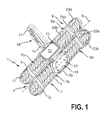
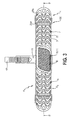
- FIG. 1 and FIG. 2 each show a perspective view of an embodiment of a holding device according to the invention 1.
- This comprises a front shell 3 and a rear shell 5 and a suspension device 18, comprising a connection 15 and an inserted therein hanger 17 or hook 17, which can be bent apart and hung over the toilet bowl edge (please refer FIG. 5 ).
- the connection 15 is realized here as a slot insert, in which the hanger 17 is inserted or from which it can be pulled out to set a desired hooking height when hanging the holding device 1 in the edge of a toilet bowl.
- the hanger 17 has a corrugation similar to a rack, which cooperates with an opening in the connection 15 so that the relative movement of the hanger 17 with respect to the connection 15 is inhibited. This results in a kind of latching function of the suspension device 18.
- the front shell 3 has a front shell outer side A 1 (see. Fig. 2 ) and a front shell inside J 1 (see. Fig. 1 ) on.
- the rear shell 5 has a rear shell outside A 2 (see. Fig. 2 ) and a rear shell inside J 2 (see. Fig. 1 ) on.
- the front shell 3 and the rear shell 5 are permanently connected to each other via three first connecting elements 23b in the form of connecting webs 23b or film hinges 23b.
- the front shell 3 has second connecting elements 23a, which are realized as latching noses 23a, which point away from the front shell outer side A 1 and are arranged as an edge of the front shell 3 facing the connection 15.
- latching noses 23a corresponding in position and shape are formed on the rear shell 5 as third connecting elements 23c latching slots 23c.
- the front shell 3 and the rear shell 5 can be made to coincide with each other so that the latching noses 23a can be inserted into the Einrastschlitze 23c and thus the holding device 1 can be closed.
- a second receiving area 19 is formed centrally on the inside of the rear tray J 2 , to which a first receiving area rear side 7b partially defining a first receiving area 7 and a second receiving area rear wall 9b defining a third receiving area 9 adjoin on both sides.
- the second receiving region 19 is delimited against the first and the third receiving region 7, 9 by a delimiting frame 20 which circulates in the interior of the rear shell 5.
- a first recording-area front side 7a and a second holding region front side 9a is formed on the front shell inside J.
- first receiving area rear side 7 b and the first receiving area front side 7 a form the first receiving area 7 and the second receiving area rear side 9 b and the second receiving area front side 9 a form the third receiving area 9 and the third receiving portion 9 are thus formed as a chamber-like, but outwardly (see below) open cavities 7, 9, in each of which a solid-like detergent unit (or more of such units) can be maintained.
- the second receiving area 19 is raised in a pedestal-like manner in comparison with the first and third receiving areas 7, 9 formed on the rear shell inside J 2 . This is realized by a recess 19 'in the rear shell outer side A 2 .
- the second receiving portion 19 on the rear shell inside J 2 a number of mounting pins 21 which protrude from the plane of the rear shell inside J 2 and serve to fix a fragrance gel as a fragrance unit.
- the front shell 3 has a passage window 11 which extends substantially along the entire inner area of the second receiving area 19, ie the area bounded by the delimiting frame 20.
- the front shell 3 on the front shell inside J 1 a circumferential recess 13, the position and dimensions of which substantially corresponds to those of the delimiting frame 20.
- the front shell 3 and the rear shell 5 are folded, the front shell 3 closes in the region of the recess 13 from the boundary frame 20.
- the second receiving region 19 is completely separated from the first and third receiving regions 7, 9, and no (dissolved) cleaning agent from the latter two regions 7, 9 can penetrate directly into the second receiving region 19 via the inner region J.
- Both the front shell 3 and the rear shell 5 have a number of passages 25a, 25b in the first receiving area 7 and in the third receiving area 9. Of these, four first elongate slot-like passages 25a - a first passage 25a per receiving area 7, 9 in the front shell 3 and rear shell 5 - are formed. A larger number of second, wave-shaped slot-like passages 25b adjoins the first passages 25a along the longitudinal extent of the holding device 1 on both sides. These passages 25a, 25b serve to admit rinsing water of the toilet bowl and the discharge of the rinsing water added with cleaning agent.
- FIGS. 1 and 2 show views of an embodiment of a flushing device 100 according to the invention in the closed state. It covers the basis of the FIGS. 1 and 2 described holding device 1, which is equipped with a fragrance unit D and two detergent units S 1 , S 2 .
- the fragrance unit D in the form of a fragrance gel D is filled in the second receiving area 19 and held firmly by the delimiting frame 20 and the fixing pins 21 in the second receiving area. It points through the passage window 11 to the outside, ie away from the rear shell inside J 2 . Through the passage window 11 an optical and haptic access to the fragrance gel D is guaranteed for a user, even from a greater distance.
- By limiting frame 20 and its positive connection with the recess 13 on the front shell inside J 1 of the front shell 3 ensures that access - including liquids - to the fragrance gel D exclusively from the front of the flushing device 100 (ie from the front shell outer side A 1 ) is possible in the closed state.
- the second receiving area 19 thus forms in the closed state of the holding device 1 a forward, to the central region of the toilet bowl, open cavity in the front shell 3.
- a first detergent unit S 1 is positioned in the first receiving area 7, a second detergent unit S 2 in the third receiving area 9.
- the two detergent units S 1 , S 2 are each formed as detergent bricks S 1 , S 2 , ie as detergent units S 1 , S 2 in a solid form. You can from near distance, ie a distance below 500 mm, through the passages 25a, 25b through recognized become. A haptic access to the detergent bricks S 1 , S 2 is hardly possible in the closed state of the rinsing device 100.
- the outer surface DF of the fragrance gel D ie those outer surface DF, which in a toilet bowl in the direction of a central portion of the toilet bowl, when properly suspending the rinsing device 100, along a common plane P or P arranged through the corresponding outer surfaces SF of the detergent blocks S 1 , S 2 is defined.
- the respective (corresponding) outer surfaces DF, SF are arranged coplanar.
- This coplanar arrangement results on the one hand from the height dimensions (from the rear shell 5 to the front shell 3) of the fragrance unit D and the detergent units S 1 , S 2 , on the other hand by the corresponding height dimensions of the first, second and third receiving areas 7, 19, 9 the second receiving area 19 practically filled up to its upper end E withWgel D. It thus extends substantially along the entire total extension of the delimiting frame 20 from the rear shell 5 in the direction of the front shell 3.
- the increased arrangement of the second receiving area 19 with respect to the other two receiving areas 7, 9 results in not unnecessarily much fragrance gel D in the receiving area 19 must be filled in order to achieve this coplanar arrangement.
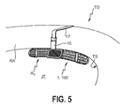
- FIG. 5 shows a perspective view of the flushing device 100 according to the invention according to the preceding figures in the proper suspension in a toilet bowl TO.
- the flushing device 100 is mounted in the edge RA of the toilet bowl TO.
- the flushing device 100 faces toward a central area JT of the toilet bowl TO; Accordingly, it has with the rear shell outside A 2 in the direction of the toilet bowl TO, more precisely in the direction of a nearest wall TS of the toilet bowl TO below the edge RA.
- flushing water is discharged from the edge RA of the toilet bowl TO or along the wall TS. It passes through some or all of the passages 25a, 25b and thereby dissolves cleaning agents of the detergent bricks S 1 , S 2 .
- the rinsing water added with cleaning agent then passes out of the rinsing device 100 via some or all of the passages 25a, 25b and is rinsed along the toilet bowl TS.
- the delimiting frame 20 Effectively prevents the detergent added rinse water directly from the first or third Receiving area 7, 9, reaches the fragrance gel D. It can rinse water, which is essentially not mixed with detergent, run directly over theWritgel D and then dried again. As a result, a washing-up effect of the fragrance gel D can be achieved.
- the fragrance gel D is therefore largely not exposed to the detergent of the detergent bricks S 1 , S 2 and can therefore act in isolation, ie substantially continuously deliver fragrance to the ambient air.
- the second receiving portion 19 is formed as part of the rear shell 5.
- the passage window 11 which is dimensioned sufficiently large for a penetration and in particular for easy viewing of the front shell outer side A 1 in the direction of the inner region J, also allows just this simple optical as haptic access - such as for evaluation by a user, whether (sufficient) fragrance unit is present and possibly for a (refill) filling, without having to open the holding device specially.
- the restricting frame 20 extends from the rear shell inner side J 2 to the front shell inner side J 1 .
- a separation of the second receiving region 19 from the first and third receiving region 7, 9 is achieved in a simple manner-without the necessary interaction of the front shell 3 and the rear shell 5, whereby an inflow of rinsing water mixed with cleaning agent between the individual receiving regions 7, 19, 9 is effective is prevented.
- the interaction of the passage window 11 with the configuration of the delimiting frame 20 results in a particular synergistic effect: namely, the second receiving area can be filled to its end, ie until it comes into contact with the front shell, due to its dimensioning , Due to the Passage window, the fragrance unit D easier and unhindered release the fragrance to the surrounding air and their surface DF better flushed by the rinse water or regularly wetted at short notice by rinse water.
- a fragrance gel D can be used, which is to be rinsed off and causes in the toilet bowl on the water film of the rinse water fragrance delivery.
- FIG. 6 shows a schematic block flow diagram illustrating an embodiment of a manufacturing method according to the invention Z for producing a flushing device.
- the description of the processes is made with reference to the preceding figures, so that reference is made to the corresponding reference numerals and the corresponding features of the holding or rinsing devices 1, 100 shown there, wherein it should also be noted in this connection that the Holding or flushing devices 1, 100 are exemplary embodiments.
- the production method Z comprises at least the following steps in the stated order, wherein the second and third steps X and W can also be reversed or carried out simultaneously:
- a holding device 1 according to the invention is provided, wherein preferably the front shell 3 and the rear shell 5 were produced together in an injection molding process and then the connection with the hook 17 takes place.
- the second receiving area 19 of the holding device 1 is equipped with a number of fragrance units D. This is preferably done by pouring a gel into the second receiving area 19.
- a third step W are the first receiving area 7 and / or possibly other receiving areas, for example, the third receiving area 9 of the holding device 1 equipped with a number of detergent units S 1 , S 2 , for example, cleaning stones S 1 , S 2 inserted.
- step V the holding device 1 is closed. All method steps can be carried out inline, ie in (for example, clocked or continuously running, timed to each other) work steps along a production line, which has a plurality of individual modules for performing the provision Y, the mounting steps X, W and V closing.
Landscapes
- Health & Medical Sciences (AREA)
- Public Health (AREA)
- Epidemiology (AREA)
- Life Sciences & Earth Sciences (AREA)
- Engineering & Computer Science (AREA)
- Hydrology & Water Resources (AREA)
- Water Supply & Treatment (AREA)
- Bidet-Like Cleaning Device And Other Flush Toilet Accessories (AREA)
Applications Claiming Priority (1)
| Application Number | Priority Date | Filing Date | Title |
|---|---|---|---|
| DE102013105316.5A DE102013105316A1 (de) | 2013-05-23 | 2013-05-23 | Haltevorrichtung und Spülvorrichtung zur Anbringung in einer Toilettenschüssel und Herstellung derselben Spülvorrichtung |
Publications (2)
| Publication Number | Publication Date |
|---|---|
| EP2806074A2 true EP2806074A2 (fr) | 2014-11-26 |
| EP2806074A3 EP2806074A3 (fr) | 2017-04-12 |
Family
ID=50396911
Family Applications (1)
| Application Number | Title | Priority Date | Filing Date |
|---|---|---|---|
| EP14162009.6A Withdrawn EP2806074A3 (fr) | 2013-05-23 | 2014-03-27 | Dispositif de fixation et distribution pour la montage dans une cuvette et méthode pour la production dudit dispositif de distribution |
Country Status (2)
| Country | Link |
|---|---|
| EP (1) | EP2806074A3 (fr) |
| DE (1) | DE102013105316A1 (fr) |
Cited By (8)
| Publication number | Priority date | Publication date | Assignee | Title |
|---|---|---|---|---|
| EP3121342A1 (fr) * | 2015-07-20 | 2017-01-25 | Werner & Mertz GmbH | Récipient pour un produit de rinçage de wc |
| ITUB20160666A1 (it) * | 2016-02-11 | 2017-08-11 | Deco Ind S Coop P A | Dispositivo di supporto per apparato igienico e apparato igienico impiegante lo stesso |
| WO2017211857A1 (fr) * | 2016-06-08 | 2017-12-14 | Buck-Chemie Gmbh | Dispositif pourvu d'un agent de nettoyage pour le domaine des toilettes |
| EP3594419A1 (fr) * | 2018-07-10 | 2020-01-15 | Eurvest S.A. | Dispositif de distribution flexible |
| USD912761S1 (en) | 2019-06-07 | 2021-03-09 | S. C. Johnson & Son, Inc. | Toilet rim-block |
| USD914131S1 (en) | 2019-06-07 | 2021-03-23 | S. C. Johnson & Son, Inc. | Toilet rim-block holder |
| USD923139S1 (en) | 2019-06-07 | 2021-06-22 | S. C. Johnson & Son, Inc. | Set of toilet rim-blocks |
| WO2022228816A1 (fr) * | 2021-04-29 | 2022-11-03 | Henkel Ag & Co. Kgaa | Cage de bloc de rebord de wc dotée d'un dispositif de retenue à pince |
Families Citing this family (1)
| Publication number | Priority date | Publication date | Assignee | Title |
|---|---|---|---|---|
| DE102021111039A1 (de) | 2021-04-29 | 2022-11-03 | Henkel Ag & Co. Kgaa | Verfahren zum Herstellen eines WC-Körbchen mit einem gelartigen Wirkstoff |
Citations (2)
| Publication number | Priority date | Publication date | Assignee | Title |
|---|---|---|---|---|
| DE4008429A1 (de) | 1990-03-16 | 1991-09-19 | Polypack R Reinders Produktion | Dosiereinrichtung fuer ein wasseraktivierbares mittel |
| EP1797251B1 (fr) | 2004-08-04 | 2009-09-09 | Reckitt Benckiser Inc. | Distributeur |
Family Cites Families (2)
| Publication number | Priority date | Publication date | Assignee | Title |
|---|---|---|---|---|
| GB0406616D0 (en) * | 2004-03-24 | 2004-04-28 | Jeyes Group Ltd | Dispenser for releasing treatment composition into a toilet bowl |
| GB2422380A (en) * | 2005-01-19 | 2006-07-26 | Reckitt Benckiser Inc | Device for dispensing a treatment composition and a fragrancing effect to a sanitary appliance |
-
2013
- 2013-05-23 DE DE102013105316.5A patent/DE102013105316A1/de not_active Withdrawn
-
2014
- 2014-03-27 EP EP14162009.6A patent/EP2806074A3/fr not_active Withdrawn
Patent Citations (2)
| Publication number | Priority date | Publication date | Assignee | Title |
|---|---|---|---|---|
| DE4008429A1 (de) | 1990-03-16 | 1991-09-19 | Polypack R Reinders Produktion | Dosiereinrichtung fuer ein wasseraktivierbares mittel |
| EP1797251B1 (fr) | 2004-08-04 | 2009-09-09 | Reckitt Benckiser Inc. | Distributeur |
Cited By (10)
| Publication number | Priority date | Publication date | Assignee | Title |
|---|---|---|---|---|
| EP3121342A1 (fr) * | 2015-07-20 | 2017-01-25 | Werner & Mertz GmbH | Récipient pour un produit de rinçage de wc |
| ITUB20160666A1 (it) * | 2016-02-11 | 2017-08-11 | Deco Ind S Coop P A | Dispositivo di supporto per apparato igienico e apparato igienico impiegante lo stesso |
| WO2017137922A1 (fr) * | 2016-02-11 | 2017-08-17 | Deco Industrie S.Coop.P.A. | Dispositif de support pour appareil hygiénique et appareil hygiénique l'utilisant |
| WO2017211857A1 (fr) * | 2016-06-08 | 2017-12-14 | Buck-Chemie Gmbh | Dispositif pourvu d'un agent de nettoyage pour le domaine des toilettes |
| EP3594419A1 (fr) * | 2018-07-10 | 2020-01-15 | Eurvest S.A. | Dispositif de distribution flexible |
| WO2020011785A1 (fr) * | 2018-07-10 | 2020-01-16 | Eurvest Sa | Dispositif de distribution flexible |
| USD912761S1 (en) | 2019-06-07 | 2021-03-09 | S. C. Johnson & Son, Inc. | Toilet rim-block |
| USD914131S1 (en) | 2019-06-07 | 2021-03-23 | S. C. Johnson & Son, Inc. | Toilet rim-block holder |
| USD923139S1 (en) | 2019-06-07 | 2021-06-22 | S. C. Johnson & Son, Inc. | Set of toilet rim-blocks |
| WO2022228816A1 (fr) * | 2021-04-29 | 2022-11-03 | Henkel Ag & Co. Kgaa | Cage de bloc de rebord de wc dotée d'un dispositif de retenue à pince |
Also Published As
| Publication number | Publication date |
|---|---|
| DE102013105316A1 (de) | 2014-11-27 |
| EP2806074A3 (fr) | 2017-04-12 |
Similar Documents
| Publication | Publication Date | Title |
|---|---|---|
| EP2806074A2 (fr) | Dispositif de fixation et distribution pour la montage dans une cuvette et méthode pour la production dudit dispositif de distribution | |
| EP3002376B1 (fr) | Corbeille wc dotée d'un élément de distribution d'eau de rinçage | |
| DE10204928B4 (de) | Abgabevorrichtung zur Abgabe eines Wirkstofffluids in die Spülflüssigkeit in einem Toilettenbecken | |
| DE60201524T2 (de) | Waschmittelspender für geschirrspülmaschine | |
| DE102008003359A1 (de) | Abgabevorrichtung zur Abgabe wenigstens eines Wirkstofffluids in das Spülwasser eines Toilettenbeckens sowie zur Beduftung der Umgebung | |
| EP2620489B1 (fr) | Dispositif de distribution d'agent actif et procédé de fabrication d'un dispositif de distribution d'agent actif | |
| EP3121342A1 (fr) | Récipient pour un produit de rinçage de wc | |
| DE202013102261U1 (de) | Haltevorrichtung und Spülvorrichtung zur Anbringung in einer Toilettenschüssel | |
| EP3477010B1 (fr) | Petit panier de wc et système de rinçage de wc | |
| EP1799921B1 (fr) | Couvercle de toilette avec un distributeur | |
| DE19945598B4 (de) | Abgabevorrichtung für die Abgabe eines Wirkstoffes | |
| DE4008429A1 (de) | Dosiereinrichtung fuer ein wasseraktivierbares mittel | |
| DE202015102159U1 (de) | Behälter | |
| DE102006050475B4 (de) | Reinigungsbehälter | |
| DE102015113834B4 (de) | Haltevorrichtung zu Halterung von Wirkstoffformkörpern in einer Toilettenschüssel mit einer Aufhängevorrichtung sowie WC-Wirkstoffabgabevorrichtung mit dieser Haltevorrichtung | |
| DE19741283B4 (de) | Vorrichtung zur Abgabe von Zusatzstoffen an das Spülwasser in Toilettenschüsseln | |
| EP2620490B1 (fr) | Dispositif de distribution d'agent actif et procédé de fabrication d'un dispositif de distribution d'agent actif | |
| DE102016100293A1 (de) | WC-Wirkstoffhalter | |
| EP2428133B1 (fr) | Dispositif de nettoyage de joints | |
| DE102015110123A1 (de) | Vorrichtung zur Aufnahme eines Toilettenreinigungsmittels | |
| EP1458939B1 (fr) | Dispositif pour delivrer un principe actif liquide dans de l'eau de chasse | |
| DE102005000792A1 (de) | Behälter zur Aufbewahrung von Papiertaschentüchern | |
| WO2020126297A1 (fr) | Dispositif destiné à recevoir un produit de nettoyage de toilettes | |
| AT395450B (de) | Vorrichtung zur abgabe eines wasserloeslichen mittels in das spuelwasser | |
| DE29811823U1 (de) | WC-Körbchen |
Legal Events
| Date | Code | Title | Description |
|---|---|---|---|
| PUAI | Public reference made under article 153(3) epc to a published international application that has entered the european phase |
Free format text: ORIGINAL CODE: 0009012 |
|
| 17P | Request for examination filed |
Effective date: 20140327 |
|
| AK | Designated contracting states |
Kind code of ref document: A2 Designated state(s): AL AT BE BG CH CY CZ DE DK EE ES FI FR GB GR HR HU IE IS IT LI LT LU LV MC MK MT NL NO PL PT RO RS SE SI SK SM TR |
|
| AX | Request for extension of the european patent |
Extension state: BA ME |
|
| PUAL | Search report despatched |
Free format text: ORIGINAL CODE: 0009013 |
|
| AK | Designated contracting states |
Kind code of ref document: A3 Designated state(s): AL AT BE BG CH CY CZ DE DK EE ES FI FR GB GR HR HU IE IS IT LI LT LU LV MC MK MT NL NO PL PT RO RS SE SI SK SM TR |
|
| AX | Request for extension of the european patent |
Extension state: BA ME |
|
| RIC1 | Information provided on ipc code assigned before grant |
Ipc: E03D 9/03 20060101ALI20170309BHEP Ipc: E03D 9/02 20060101AFI20170309BHEP |
|
| R17P | Request for examination filed (corrected) |
Effective date: 20170929 |
|
| RBV | Designated contracting states (corrected) |
Designated state(s): AL AT BE BG CH CY CZ DE DK EE ES FI FR GB GR HR HU IE IS IT LI LT LU LV MC MK MT NL NO PL PT RO RS SE SI SK SM TR |
|
| GRAP | Despatch of communication of intention to grant a patent |
Free format text: ORIGINAL CODE: EPIDOSNIGR1 |
|
| RIC1 | Information provided on ipc code assigned before grant |
Ipc: E03D 9/03 20060101ALI20180214BHEP Ipc: E03D 9/02 20060101AFI20180214BHEP |
|
| INTG | Intention to grant announced |
Effective date: 20180307 |
|
| STAA | Information on the status of an ep patent application or granted ep patent |
Free format text: STATUS: THE APPLICATION IS DEEMED TO BE WITHDRAWN |
|
| 18D | Application deemed to be withdrawn |
Effective date: 20180718 |