EP2806081B1 - Boîte à eau - Google Patents
Boîte à eau Download PDFInfo
- Publication number
- EP2806081B1 EP2806081B1 EP14169113.9A EP14169113A EP2806081B1 EP 2806081 B1 EP2806081 B1 EP 2806081B1 EP 14169113 A EP14169113 A EP 14169113A EP 2806081 B1 EP2806081 B1 EP 2806081B1
- Authority
- EP
- European Patent Office
- Prior art keywords
- water
- water box
- flow
- receptacle
- outlet
- Prior art date
- Legal status (The legal status is an assumption and is not a legal conclusion. Google has not performed a legal analysis and makes no representation as to the accuracy of the status listed.)
- Active
Links
Images

Classifications
-
- E—FIXED CONSTRUCTIONS
- E04—BUILDING
- E04D—ROOF COVERINGS; SKY-LIGHTS; GUTTERS; ROOF-WORKING TOOLS
- E04D13/00—Special arrangements or devices in connection with roof coverings; Protection against birds; Roof drainage ; Sky-lights
- E04D13/04—Roof drainage; Drainage fittings in flat roofs, balconies or the like
- E04D13/0404—Drainage on the roof surface
- E04D13/0409—Drainage outlets, e.g. gullies
- E04D13/0431—Drainage outlets, e.g. gullies with horizontal evacuation over the border of the roof
-
- E—FIXED CONSTRUCTIONS
- E04—BUILDING
- E04D—ROOF COVERINGS; SKY-LIGHTS; GUTTERS; ROOF-WORKING TOOLS
- E04D13/00—Special arrangements or devices in connection with roof coverings; Protection against birds; Roof drainage ; Sky-lights
- E04D13/04—Roof drainage; Drainage fittings in flat roofs, balconies or the like
- E04D13/064—Gutters
- E04D13/0645—Connections between gutter and down pipe
Definitions
- the present invention generally relates to the field of collecting and evacuating rainwater, more particularly the reception of rainwater at the outlet of pipe emerging from a flat roof of a building. More specifically, the present invention relates to a water box intended to be fixed on the facade of a building.
- the document JP2008274717 shows an upward open water box, with an entrance to the parapet traverse and an outlet to the single cylindrical downcomer.
- Other examples of water boxes are described in the documents JP2008180040 , JP2007002616 and JP2008180043 , in which the water boxes have a substantially U-shaped back wall to facilitate mounting to the facade. At the same time, the water boxes provide a concealment of the parapet traverse for a better aesthetic integration in the facade of the building.
- the documents JP 2008 133615 and JP 2009 052317 disclose a water box according to the preamble of claim 1.
- the present invention aims to improve the hydraulic performance of water boxes.
- the present invention provides a water box according to claim 1.
- the water box is intended to be fixed on an outer side of a wall surrounding a substantially horizontal surface of a building such as an acroterium comprising a tank body for receiving a stream of water, the tank body comprising a bottom, a rear wall for attachment to an outer side of a parapet, and at least one side wall, and an outlet to a descendant with a longitudinal output axis.
- a water flow reorientation device is positioned in the tank body, and is intended to partially intercept the flow of water in the tank body and to direct it towards the outlet.
- the redirecting device comprises a receptacle positioned in the reservoir body, the receptacle including an upper body, the upper body being oriented along a main reservoir axis.
- the reservoir axis is offset from the axis of the outlet, the reservoir axis being substantially vertical when the water box is fixed in the operative position
- the present invention proposes a device for redirecting the flow of water, adapted to intercept the flow of water at the outlet of a paratrooper, which is substantially horizontal, in order to redirect, as soon as it falls, the flow of water towards the water. vertical exit.
- the reorientation of the trajectories of the water significantly improves its entonpulsion in the vertical stump, and the hydraulic performances of the whole. Most of the time, it will be rain water but it may also be water resulting from excessive cleaning or watering etc.
- the receptacle is designed to intercept the water flow at the acroterion outlet and create a water circulation path to direct the flow of water to the outlet.
- a receptacle preferably chosen at a height substantially equivalent to the water thread of the acroterion crossing, makes it possible to intercept the flow of water and to define a preferential flow path towards the outlet, which can also ideally induce an effect optional vortex.
- a flow orientation path can be provided to direct the intercepted flow to the vertical exit.
- the receptacle comprises a base, in the extension of the upper body, the base comprising an inclined pan, in order to redirect the flow of water along the axis.
- the base extends beyond the bottom.
- the receptacle is thus adapted to divert, at its base, the blade of water flowing at the bottom, from front to rear. By extending the base beyond the bottom, it also divides the water slide that flows in the bottom in two, generating a call for water and increasing the speed of water circulation.
- the rear wall is intended to be fixed to a facade the rear wall comprising a lid.
- the cap has a "U" shape. By providing a U shape, the exit of the acroterion can be integrated in the rear wall of the water box, which improves the aesthetics of the whole.
- the tank body is provided with an overflow warning for the flow of a trickle of water in case of saturation of the water box.
- the upper container body serves as an overflow in case of saturation of the water box.
- a partition is disposed in the reservoir body between the upper receptacle body and the rear wall.
- the partition is arranged perpendicularly to the rear wall.
- the present invention provides a water box with a water flow reorientation device ensuring optimization of the water intonation in the vertical descendant.
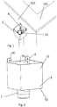
- the Figures 1 to 5 show a water box 1 according to an aspect of the present invention to be mounted on a facade 100 of a building.
- the water box 1 is positioned substantially to the right of the parapet traverse 4 of a flat roof 101, for the reception of rainwater acroterion outlet opening from the flat roof of a building.
- the water box 1 comprises a tank body 5 for the reception of rainwater, with an inlet 6 for the acroterion crossing 4 and an outlet 7 to a descendant 8 oriented along a substantially vertical axis X when the water box is mounted to the facade 100.
- the tank body 5 comprises a bottom 50 opening on the outlet 7 to the descendant, a side wall 52 and a rear wall 55 intended to bear against the facade.
- the tank body 5 is substantially parallelepipedal, the rear wall 55 and the side wall 52 forming a cubic type assembly.
- the tank body may be for example of cylindrical shape, with the rear wall 55 being a substantially flat wall to bear against the front and the side wall 52 of curved shape.
- the rear wall 55 comprises at least one ear or lug 16.
- the at least one lug 16 can be cut, and comprises one or more mounting holes 17, allowing the passage of a fixing screw.
- two ears provided with two oblong holes are provided.
- the rear wall 55 is provided with a cover 56 to form the inlet 6 to integrate the acroterion crossing at the rear thereof, for both aesthetic and hydraulic reasons.
- the inlet 6 is U-shaped.
- the entry 6 for the parapet traverse is integrated in the rear wall 55.
- this example is not limiting and, in some applications, the acroterial crossing may lead to the top of the rear wall.
- a water flow reorientation device 11 is positioned inside the tank body 5, to partially intercept the water flow at the acroterion outlet, which is substantially horizontal, and to orient it in the outlet 7 and the descendant 8, substantially vertical when the box is in the operative position.
- the water flow reorientation device comprises a receptacle 11, designed to have a height substantially equivalent to the water thread of the parapet traverse.
- the receptacle 11 comprises an upper receptacle body 30 substantially perpendicular to the bottom 50 and a base 40, in the extension of the upper receptacle body 30, and protruding from the bottom 50 and extends and forms the outlet 7.
- the receptacle 11 is oriented substantially vertically when the water box is fixed on the facade, with the outlet 7 of the base 40 extending inside the socket of the descendant 8, when the water box is in the operative position.
- the upper receptacle body 30 is substantially cylindrical, with a rear wall side rear face 55 and a front face 32 opposite to the rear face.
- the upper receptacle body is oriented along a substantially vertical main reservoir axis R substantially when the water box is attached to the facade.
- the tank axis R is offset from the X axis of the outlet 7.
- the base 40 comprises an inclined wall 42, inclined towards the rear wall 55, making the transition between the front face 32 of the upper receptacle body 30, substantially vertical in the operative position, and the outlet 7 towards the descendant.
- the upper receptacle body 30, in particular the front face 32 of the cylindrical body of the receptacle 11, operates a damming effect and diverts the leaf of water circulating at the bottom of the box.
- the cylindrical receptacle is thus adapted to divert, at its base 40, the blade of water flowing at the bottom, from the front to the rear, and disturbs the sound of the water in the cylindrical stump.
- the base 40 of the cylinder is provided to extend inside the socket of the descendant, dividing it in two, which generates a call for water between two flows and increases the speed of water flow.
- a partition 95 arranged in the reservoir body between the water flow reorientation device 30 and the rear wall 55 of the water box, prevents the two streams of water that arrive on the rear from hitting the front and embarrass themselves for the sounding.
- the partition 95 in the tank body also contributes to the hydraulic efficiency of the water box.
- the water box 1 also comprises a warning overflow 15 provided for materializing the flow of a trickle of water in a rear angle in the event of saturation, by plugging or obstruction for example, of the water box 1.
- the warning overflow 15 is intended to serve as a visual alert, and the receptacle 30 serves as overflow when charging the water box.
- the height of the upper edge of the receptacle 30 is less than the height of the lid "U".
- the water box 1 is preferably monobloc, with an opening on the upper part.
- a monobloc box has the advantage of being simple to manufacture and install, one piece to be fixed at a facade, to have a water box operational.
- the rear wall 55 of the water box 1 also participates in the delimitation of the receptacle 30, c that is, the reorientation of the flow.
- the one-piece structure and the arrangement of the water box according to the invention make it possible to dispense with additional pieces of the water reorientation bend type redirecting the incoming horizontal water flow into a vertical flow. at the end of the elbow.
- the present invention provides a water box for collecting rainwater from a flat roof and evacuation to a gutter down the front.
- a receptacle makes it possible to partially intercept the flow of water and to direct it downhill to improve the drainage of rainwater.
- the receptacle also makes it possible to limit the hydraulic disturbances and to speed up the sounding of the water.
Landscapes
- Engineering & Computer Science (AREA)
- Architecture (AREA)
- Civil Engineering (AREA)
- Structural Engineering (AREA)
- Building Environments (AREA)
- Casings For Electric Apparatus (AREA)
- Sink And Installation For Waste Water (AREA)
- Sewage (AREA)
Description
- La présente invention concerne généralement le domaine de la collecte et l'évacuation des eaux de pluie, plus particulièrement la réception des eaux de pluie en sortie de tuyau débouchant d'un toit plat d'un bâtiment. Plus précisément, la présente invention concerne une boîte à eau destinée à être fixée sur la façade d'un bâtiment.
- Afin de faciliter l'évacuation d'eaux de pluie d'un toit plat entouré par un acrotère, des boîtes à eaux ont été développées, pour réceptionner les eaux en sortie de traversée d'acrotère. Un tuyau traversant l'acrotère débouche dans la boîte et les eaux de pluie sont redirigées vers un descendant vertical.
- Le document
JP2008274717 JP2008180040 JP2007002616 JP2008180043 JP 2008 133615 JP 2009 052317 - La présente invention a pour but d'améliorer les performances hydrauliques des boîtes à eau.
- La présente invention propose une boîte à eau selon la revendication 1. La boîte à eau est destinée à être fixée sur un côté extérieur d'une paroi entourant une surface sensiblement horizontale d'un bâtiment telle un acrotère comprenant un corps de réservoir pour la réception d'un flux d'eau, le corps de réservoir comprenant un fond, une paroi arrière pour la fixation sur un côté extérieur d'un acrotère, et au moins une paroi latérale, et une sortie vers un descendant avec un axe longitudinal de sortie. Un dispositif de réorientation de flux d'eau est positionné dans le corps de réservoir, et est destiné à intercepter partiellement le flux d'eau dans le corps de réservoir et à l'orienter vers la sortie. Le dispositif de réorientation comprend un réceptacle positionné dans le corps de réservoir, le réceptacle comprenant un corps supérieur, le corps supérieur étant orienté selon un axe de réservoir principal. L'axe de réservoir est décalé de l'axe de la sortie, l'axe de réservoir étant sensiblement vertical lorsque la boite à eau est fixée en position fonctionnelle
- Ainsi la présente invention propose un dispositif de réorientation de flux d'eau, adapté pour intercepter le flux d'eau en sortie d'acrotère, sensiblement horizontal, afin de réorienter, au plus tôt dans sa chute, le flux d'eau vers la sortie verticale. La réorientation des trajectoires de l'eau améliore significativement son entonnement dans le moignon vertical, et les performances hydrauliques de l'ensemble. La plupart du temps, il va s'agir d'eau de pluie mais il peut tout aussi bien s'agir d'eau résultant d'un nettoyage ou d'un arrosage exagéré etc.
- Le réceptacle est prévu pour intercepter le flux d'eau en sortie d'acrotère et créer un chemin de circulation d'eau pour orienter le flux d'eau vers la sortie. Un réceptacle, de préférence choisi à hauteur sensiblement équivalente au fil d'eau de la traversée d'acrotère, permet d'intercepter le flux d'eau et de définir un chemin d'écoulement préférentiel vers la sortie, pouvant idéalement aussi induire un effet vortex optionnel.
- En prévoyant un décalage des axes de réservoir principal et de sortie, on peut prévoir un chemin d'orientation de flux, pour orienter le flux intercepté vers la sortie verticale.
- Selon un mode de réalisation de l'invention, le réceptacle comprend une base, dans le prolongement du corps supérieur, la base comprenant un pan incliné, afin de rediriger le flux d'eau selon l'axe. De préférence, la base se prolonge au-delà du fond. Avantageusement, le réceptacle est ainsi adapté pour détourner, à sa base, la lame d'eau qui circule au fond, de l'avant vers l'arrière. En prolongeant la base au-delà du fond, cela permet également de diviser la lame d'eau qui circule au fond en deux, engendrant un appel d'eau et augmentant ainsi la vitesse de circulation d'eau.
- Dans un mode de réalisation, la paroi arrière est destinée à être fixée à une façade la paroi arrière comprenant un opercule. De préférence, l'opercule a une forme en " U ". En prévoyant une forme de U, la sortie de l'acrotère peut être intégrée dans la paroi arrière de la boîte à eau, ce qui améliore l'esthétique de l'ensemble.
- Dans un mode de réalisation, le corps de réservoir est muni d'un trop-plein d'alerte pour l'écoulement d'un filet d'eau en cas de saturation de la boîte à eau. De préférence, le corps supérieur de réceptacle sert comme trop-plein en cas de saturation de la boîte à eau.
- Selon l'invention, une cloison est disposée dans le corps de réservoir entre le corps supérieur de réceptacle et la paroi arrière. La cloison est disposée perpendiculairement à la paroi arrière. Une telle cloison permet d'améliorer l'efficacité hydraulique en évitant que deux flux d'eau qui arrivent sur l'arrière se percutent frontalement et se gênent pour l'entonnement.
- La présente invention propose une boîte à eau avec un dispositif de réorientation de flux d'eau assurant une optimisation de l'entonnement de l'eau dans le descendant vertical.
- L'invention sera mieux comprise, et d'autres buts, détails, caractéristiques et avantages de celle-ci apparaîtront plus clairement au cours de la description suivante de plusieurs modes de réalisation de l'invention, donnée à titre d'exemple non limitatif, en référence aux dessins suivants, parmi lesquels :
- la
figure 1 montre une boîte à eau fixée à une façade selon un aspect de la présente invention, - la
figure 2 est une vue d'une boîte à eau selon un aspect de la présente invention, - la
figure 3 est une vue arrière d'une boîte à eau selon un aspect de la présente invention, - la
figure 4 est une vue en coupe éclatée d'une boîte à eau selon un aspect de la présente invention, - la
figure 5 est une vue de dessus d'une boîte à eau selon un aspect de la présente invention. - Sur les figures, des éléments identiques sont indiqués par des numéros de référence identiques.
- Les
figures 1 à 5 montrent une boîte à eau 1 selon un aspect de la présente invention destinée à être montée sur une façade 100 d'un bâtiment. La boîte à eau 1 est positionnée sensiblement au droit de la traversée d'acrotère 4 d'un toit plat 101, pour la réception des eaux de pluie en sortie d'acrotère débouchant du toit plat d'un bâtiment. - La boîte à eau 1 comprend un corps de réservoir 5 pour la réception des eaux de pluie, avec une entrée 6 pour la traversée 4 d'acrotère et une sortie 7 vers un descendant 8 orienté selon un axe X sensiblement vertical lorsque la boîte à eau est montée à la façade 100.
- Le corps de réservoir 5 comprend un fond 50 débouchant sur la sortie 7 vers le descendant, une paroi latérale 52 et une paroi arrière 55 destinée à venir en appui contre la façade.
- Dans le mode de réalisation représenté, le corps de réservoir 5 est sensiblement parallélépipédique, la paroi arrière 55 et la paroi latérale 52 formant un ensemble de type cubique. Bien entendu d'autres formes sont envisageables, le corps de réservoir peut être par exemple de forme cylindrique, avec la paroi arrière 55 étant une paroi de forme sensiblement plane pour venir en appui contre la façade et la paroi latérale 52 de forme incurvée.
- Des moyens de fixation de la boîte à eau à la façade sont prévus. Comme bien vu sur les
figures 2 à 4 , la paroi arrière 55 comprend au moins une oreille ou patte de fixation 16. La au moins une oreille 16 peut être découpable, et comprend un ou plusieurs trous de fixation 17, permettant le passage d'une vis de fixation. De préférence, deux oreilles munies de deux trous oblongues sont prévues. - La paroi arrière 55 est munie d'un opercule 56 afin de former l'entrée 6 pour intégrer la traversée d'acrotère à l'arrière de celle-ci, pour des raisons à la fois esthétiques et hydrauliques. De préférence, l'entrée 6 est en forme de U. Dans le mode de réalisation ainsi représenté, l'entrée 6 pour la traversée d'acrotère est intégrée dans la paroi arrière 55. Bien entendu, cet exemple n'est pas limitatif et, dans certaines applications, la traversée d'acrotère peut déboucher au dessus de la paroi arrière.
- Un dispositif de réorientation de flux d'eau 11 est positionné à l'intérieur du corps de réservoir 5, pour intercepter partiellement le flux d'eau en sortie d'acrotère, qui est sensiblement horizontal, et l'orienter dans la sortie 7 et le descendant 8, sensiblement vertical lorsque la boîte est en position fonctionnelle. Dans le mode de réalisation représenté, le dispositif de réorientation de flux d'eau comprend un réceptacle 11, prévu pour avoir une hauteur sensiblement équivalente au fil d'eau de la traversée d'acrotère.
- Le réceptacle 11 comprend un corps supérieur de réceptacle 30 sensiblement perpendiculaire au fond 50 et une base 40, dans le prolongement du corps supérieur de réceptacle 30, et qui dépasse du fond 50 et se prolonge et forme la sortie 7. Le réceptacle 11 est orienté sensiblement verticalement lorsque la boîte à eau est fixée sur la façade, avec la sortie 7 de la base 40 se prolongeant à l'intérieur de l'emboîture du descendant 8, lorsque la boîte à eau est en position fonctionnelle.
- Le corps supérieur de réceptacle 30 est sensiblement cylindrique, avec une face arrière 35 côté paroi arrière 55 et une face avant 32 opposée à la face arrière. Le corps supérieur de réceptacle est orienté selon un axe longitudinal de réservoir principal R sensiblement vertical lorsque la boîte à eau est fixée à la façade. L'axe de réservoir R est décalé de l'axe X de la sortie 7.
- La base 40 comprend une paroi inclinée 42, selon une inclinaison vers la paroi arrière 55, faisant la transition entre la face avant 32 du corps supérieur de réceptacle 30, sensiblement vertical en position fonctionnelle, et la sortie 7 vers le descendant. Ainsi, le corps supérieur de réceptacle 30, en particulier la face avant 32 du corps cylindrique du réceptacle 11, opère un effet de barrage et détourne la lame d'eau circulant en fond de boîte. Le réceptacle cylindrique est ainsi adapté pour détourner, à sa base 40, la lame d'eau qui circule au fond, de l'avant vers l'arrière, et perturbe l'entonnement de l'eau dans le moignon cylindrique.
- La réorientation des trajectoires de l'eau améliore significativement son entonnement dans le moignon vertical, et les performances hydrauliques de l'ensemble. De plus, la base 40 du cylindre est prévue pour se prolonger à l'intérieur de l'emboîture du descendant, la divisant en deux, ce qui engendre un appel d'eau entre deux flux et augmente la vitesse de circulation d'eau.
- Une cloison 95, agencée dans le corps de réservoir entre le dispositif de réorientation de flux d'eau 30 et la paroi arrière 55 de la boîte à eau, évite que les deux flux d'eau qui arrivent sur l'arrière se percutent frontalement et se gênent pour l'entonnement. Ainsi, la cloison 95 dans le corps de réservoir participe également à l'efficacité hydraulique de la boîte à eau.
- Dans une forme de réalisation, la boîte à eau 1 comprend également un trop-plein d'alerte 15 prévu pour matérialiser l'écoulement d'un filet d'eau dans un angle arrière en cas de saturation, par bouchage ou obstruction par exemple, de la boîte à eau 1.
- Le trop-plein d'alerte 15 est prévu pour servir d'alerte visuelle, et le réceptacle 30 sert de trop-plein en cas de mise en charge de la boîte à eau. La hauteur de l'arête supérieure du réceptacle 30 est inférieure à la hauteur de l'opercule en « U ». Ainsi, si la sortie 7 est obstruée, par exemple par des feuilles, l'eau monte en charge et l'eau va passer dans le réceptacle 30 par débordement.
- La boîte à eau 1 est de préférence monobloc, avec une ouverture sur la partie supérieure.
- Une boîte monobloc présente l'avantage d'être simple à fabriquer et à installer, une seule pièce étant à fixer au niveau d'une façade, pour avoir une boîte à eau opérationnelle. De plus, contrairement aux dispositifs antérieurs dans lesquels la paroi arrière de la boite à eau a pour seule fonction la fixation à une remontée d'acrotère, la paroi arrière 55 de la boîte à eau 1 participe également à la délimitation du réceptacle 30, c'est-à-dire à la réorientation du flux.
- Ainsi, la structure monobloc et l'agencement de la boîte à eau selon l'invention permettent de s'affranchir de pièces additionnelles du type coude de réorientation d'eau réorientant le flux d'arrivée d'eau horizontal en entrée en un flux vertical en sortie de coude.
- En somme, il reste à constater que la présente invention propose une boîte à eau pour la collecte des eaux de pluie d'un toit plat et l'évacuation vers une descente de gouttière en façade. Un réceptacle permet d'intercepter partiellement le flux d'eau et l'orienter dans le descendant afin d'améliorer l'évacuation des eaux de pluie. Le réceptacle permet également de limiter les perturbations hydrauliques et d'accélérer l'entonnement de l'eau.
Claims (7)
- Boîte à eau (1) destinée à être fixée sur un côté extérieur d'une paroi entourant une surface sensiblement horizontale d'un bâtiment telle un acrotère comprenant :- un corps de réservoir (5) pour la réception d'un flux d'eau, le corps de réservoir (5) comprenant un fond (50), une paroi arrière (55) pour la fixation sur un côté extérieur d'un acrotère, et au moins une paroi latérale (52),- une sortie (7) vers un descendant (8) avec un axe longitudinal de sortie (X),- un dispositif de réorientation de flux d'eau (11), positionné dans le corps de réservoir (5), destiné à intercepter partiellement le flux d'eau dans le corps de réservoir et à l'orienter vers la sortie (7), le dispositif de réorientation comprenant un réceptacle (11) pour créer un chemin de circulation d'eau pour orienter le flux d'eau vers la sortie (7), le réceptacle comprenant un corps supérieur (30), dans lequel le corps supérieur est orienté selon un axe de réservoir principal (R), l'axe de réservoir (R) étant décalé de l'axe (X) de la sortie (7), l'axe de réservoir (R) étant sensiblement vertical lorsque la boite à eau est fixée en position fonctionnelle,- caractérisée en ce qu'une cloison (95) est disposée dans le corps de réservoir entre le corps supérieur de réceptacle (30) et la paroi arrière (55), la cloison étant disposée perpendiculairement à la paroi arrière afin d'éviter que deux flux d'eau qui arrivent sur l'arrière se percutent frontalement et se gênent pour l'entonnement.
- Boîte à eau selon la revendication 1, le réceptacle (11) comprenant une base (40), dans le prolongement du corps supérieur (30), la base comprenant un pan incliné (12), afin de rediriger le flux d'eau selon l'axe (X).
- Boîte à eau selon la revendication précédente, dans laquelle la base (40) se prolonge au-delà du fond (50).
- Boîte à eau selon l'une quelconque des revendications précédentes, la paroi arrière (55) étant destinée à être fixée à une façade, la paroi arrière (55) comprenant un opercule (56).
- Boîte à eau selon la revendication 4, ledit opercule (56) ayant une forme en « U ».
- Boîte à eau selon l'une quelconque des revendications précédentes, dans laquelle le corps de réservoir (5) est muni d'un trop-plein d'alerte (15) pour l'écoulement d'un filet d'eau en cas de saturation de la boîte à eau (1).
- Boîte à eau selon l'une quelconque des revendications 1 à 6, dans laquelle le corps supérieur de réceptacle (30) sert comme trop-plein en cas de saturation de la boite à eau (1).
Applications Claiming Priority (1)
| Application Number | Priority Date | Filing Date | Title |
|---|---|---|---|
| FR1354676A FR3005975B1 (fr) | 2013-05-24 | 2013-05-24 | Boite a eau |
Publications (2)
| Publication Number | Publication Date |
|---|---|
| EP2806081A1 EP2806081A1 (fr) | 2014-11-26 |
| EP2806081B1 true EP2806081B1 (fr) | 2018-03-07 |
Family
ID=48980051
Family Applications (1)
| Application Number | Title | Priority Date | Filing Date |
|---|---|---|---|
| EP14169113.9A Active EP2806081B1 (fr) | 2013-05-24 | 2014-05-20 | Boîte à eau |
Country Status (4)
| Country | Link |
|---|---|
| EP (1) | EP2806081B1 (fr) |
| ES (1) | ES2666654T3 (fr) |
| FR (1) | FR3005975B1 (fr) |
| TR (1) | TR201807709T4 (fr) |
Cited By (1)
| Publication number | Priority date | Publication date | Assignee | Title |
|---|---|---|---|---|
| EP4603654A1 (fr) | 2024-02-14 | 2025-08-20 | RÖSLE GROUP GmbH | Boîte collectrice d'eau pour un système de drainage de toit et système de drainage de toit |
Citations (1)
| Publication number | Priority date | Publication date | Assignee | Title |
|---|---|---|---|---|
| JP2009030314A (ja) * | 2007-07-26 | 2009-02-12 | Panasonic Electric Works Co Ltd | 集水ます |
Family Cites Families (9)
| Publication number | Priority date | Publication date | Assignee | Title |
|---|---|---|---|---|
| JPH0996068A (ja) * | 1995-09-29 | 1997-04-08 | Tanita Haujingu Wear:Kk | 雨とい用集水ます |
| JPH10169121A (ja) * | 1996-12-12 | 1998-06-23 | Inoac Corp | ゴム製ジョウゴ |
| JPH10205088A (ja) * | 1997-01-28 | 1998-08-04 | Sekisui Chem Co Ltd | 排水枡 |
| JP4483721B2 (ja) | 2005-06-27 | 2010-06-16 | パナソニック電工株式会社 | 排水桝 |
| JP2008133615A (ja) * | 2006-11-27 | 2008-06-12 | Matsushita Electric Works Ltd | 集水ますの躯体取付構造 |
| JP4821632B2 (ja) | 2007-01-26 | 2011-11-24 | パナソニック電工株式会社 | 集水ます |
| JP4821631B2 (ja) | 2007-01-26 | 2011-11-24 | パナソニック電工株式会社 | 雨樋集水ます |
| JP2008274717A (ja) | 2007-05-07 | 2008-11-13 | Yamaso:Kk | バルコニー及び/又はベランダ用熱可塑性樹脂製横型ドレン |
| JP4748130B2 (ja) * | 2007-08-28 | 2011-08-17 | パナソニック電工株式会社 | 雨水取り出し装置 |
-
2013
- 2013-05-24 FR FR1354676A patent/FR3005975B1/fr active Active
-
2014
- 2014-05-20 ES ES14169113.9T patent/ES2666654T3/es active Active
- 2014-05-20 TR TR2018/07709T patent/TR201807709T4/tr unknown
- 2014-05-20 EP EP14169113.9A patent/EP2806081B1/fr active Active
Patent Citations (1)
| Publication number | Priority date | Publication date | Assignee | Title |
|---|---|---|---|---|
| JP2009030314A (ja) * | 2007-07-26 | 2009-02-12 | Panasonic Electric Works Co Ltd | 集水ます |
Cited By (1)
| Publication number | Priority date | Publication date | Assignee | Title |
|---|---|---|---|---|
| EP4603654A1 (fr) | 2024-02-14 | 2025-08-20 | RÖSLE GROUP GmbH | Boîte collectrice d'eau pour un système de drainage de toit et système de drainage de toit |
Also Published As
| Publication number | Publication date |
|---|---|
| FR3005975B1 (fr) | 2015-11-27 |
| EP2806081A1 (fr) | 2014-11-26 |
| FR3005975A1 (fr) | 2014-11-28 |
| TR201807709T4 (tr) | 2018-06-21 |
| ES2666654T3 (es) | 2018-05-07 |
Similar Documents
| Publication | Publication Date | Title |
|---|---|---|
| FR2907144A1 (fr) | Filtre pour tuyau de descente d'eaux | |
| EP0052030B1 (fr) | Dispositif pour recueillir un liquide tombant librement et son application à une installation de mise en contact à contre-courant d'un liquide avec un gaz | |
| EP2166909A1 (fr) | Receveur extra-plat a poser avec evacuation integree | |
| EP1034337B1 (fr) | Dispositif d'evacuation des eaux | |
| EP2806081B1 (fr) | Boîte à eau | |
| CA2129020A1 (fr) | Recuperateur automatique d'eau pluviale sur conduit vertical d'evacuation | |
| WO2005061815A1 (fr) | Dispositif d'evacuation d'un liquide et dispositif de guidage de liquide correspondant | |
| EP2107185B1 (fr) | Ensemble comprenant un poteau de clôture et un boîtier | |
| FR2947305A1 (fr) | Dispositif d'eolienne de toiture | |
| FR2926874A1 (fr) | Grille obturant l'ouverture d'un local de pompe a chaleur de chauffage d'un batiment | |
| EP3636857B1 (fr) | Dispositif d'écrémage de piscine et piscine munie de celui-ci | |
| EP1600570B1 (fr) | Abri à plusieurs éléments de toiture adjacents réglables | |
| EP1302397A1 (fr) | Balcon pour une cabine de navire | |
| FR2675171A1 (fr) | Dispositif pour la recuperation de l'eau pluviale. | |
| AU2011101308A4 (en) | Rain Water Retrieval System | |
| EP3579945B1 (fr) | Boîtier destiné à être disposé sur un véhicule et système d'arme comprenant un tel boîtier | |
| EP2090702B1 (fr) | Pièce de montage | |
| FR2975345A1 (fr) | Dispositif d'etancheite pour extracteur d'air de ventilation pour vehicule automobile | |
| EP1913854B1 (fr) | Cabine de douche avec rebord | |
| EP4703524A1 (fr) | Véhicule avec système hydraulique anti-refoulement d'air | |
| FR3017634A1 (fr) | Descente d'eau pluviale en sortie d'une gouttiere de toit d'une construction | |
| FR3025547A1 (fr) | Systeme de goulotte avec bac tampon integre pour realiser des piscines dites miroir | |
| FR2855842A1 (fr) | Exutoire de fumees a haute performance aeraulique, specifiquement adapte pour des voutes de toitures de constructions ou de batiments | |
| FR3016430B1 (fr) | Extracteur statique pour conduit d’evacuation d’air ou d’aeration | |
| FR2790822A1 (fr) | Buse pour commander un ecoulement d'air dans un local |
Legal Events
| Date | Code | Title | Description |
|---|---|---|---|
| PUAI | Public reference made under article 153(3) epc to a published international application that has entered the european phase |
Free format text: ORIGINAL CODE: 0009012 |
|
| 17P | Request for examination filed |
Effective date: 20140520 |
|
| AK | Designated contracting states |
Kind code of ref document: A1 Designated state(s): AL AT BE BG CH CY CZ DE DK EE ES FI FR GB GR HR HU IE IS IT LI LT LU LV MC MK MT NL NO PL PT RO RS SE SI SK SM TR |
|
| AX | Request for extension of the european patent |
Extension state: BA ME |
|
| R17P | Request for examination filed (corrected) |
Effective date: 20150526 |
|
| RBV | Designated contracting states (corrected) |
Designated state(s): AL AT BE BG CH CY CZ DE DK EE ES FI FR GB GR HR HU IE IS IT LI LT LU LV MC MK MT NL NO PL PT RO RS SE SI SK SM TR |
|
| 17Q | First examination report despatched |
Effective date: 20160617 |
|
| GRAP | Despatch of communication of intention to grant a patent |
Free format text: ORIGINAL CODE: EPIDOSNIGR1 |
|
| INTG | Intention to grant announced |
Effective date: 20170922 |
|
| GRAS | Grant fee paid |
Free format text: ORIGINAL CODE: EPIDOSNIGR3 |
|
| GRAA | (expected) grant |
Free format text: ORIGINAL CODE: 0009210 |
|
| AK | Designated contracting states |
Kind code of ref document: B1 Designated state(s): AL AT BE BG CH CY CZ DE DK EE ES FI FR GB GR HR HU IE IS IT LI LT LU LV MC MK MT NL NO PL PT RO RS SE SI SK SM TR |
|
| REG | Reference to a national code |
Ref country code: GB Ref legal event code: FG4D Free format text: NOT ENGLISH |
|
| REG | Reference to a national code |
Ref country code: CH Ref legal event code: EP Ref country code: AT Ref legal event code: REF Ref document number: 976718 Country of ref document: AT Kind code of ref document: T Effective date: 20180315 |
|
| REG | Reference to a national code |
Ref country code: IE Ref legal event code: FG4D Free format text: LANGUAGE OF EP DOCUMENT: FRENCH |
|
| REG | Reference to a national code |
Ref country code: DE Ref legal event code: R096 Ref document number: 602014021872 Country of ref document: DE |
|
| REG | Reference to a national code |
Ref country code: ES Ref legal event code: FG2A Ref document number: 2666654 Country of ref document: ES Kind code of ref document: T3 Effective date: 20180507 |
|
| REG | Reference to a national code |
Ref country code: FR Ref legal event code: PLFP Year of fee payment: 5 |
|
| REG | Reference to a national code |
Ref country code: NL Ref legal event code: MP Effective date: 20180307 |
|
| REG | Reference to a national code |
Ref country code: LT Ref legal event code: MG4D |
|
| PG25 | Lapsed in a contracting state [announced via postgrant information from national office to epo] |
Ref country code: LT Free format text: LAPSE BECAUSE OF FAILURE TO SUBMIT A TRANSLATION OF THE DESCRIPTION OR TO PAY THE FEE WITHIN THE PRESCRIBED TIME-LIMIT Effective date: 20180307 Ref country code: CY Free format text: LAPSE BECAUSE OF FAILURE TO SUBMIT A TRANSLATION OF THE DESCRIPTION OR TO PAY THE FEE WITHIN THE PRESCRIBED TIME-LIMIT Effective date: 20180307 Ref country code: HR Free format text: LAPSE BECAUSE OF FAILURE TO SUBMIT A TRANSLATION OF THE DESCRIPTION OR TO PAY THE FEE WITHIN THE PRESCRIBED TIME-LIMIT Effective date: 20180307 Ref country code: NO Free format text: LAPSE BECAUSE OF FAILURE TO SUBMIT A TRANSLATION OF THE DESCRIPTION OR TO PAY THE FEE WITHIN THE PRESCRIBED TIME-LIMIT Effective date: 20180607 Ref country code: FI Free format text: LAPSE BECAUSE OF FAILURE TO SUBMIT A TRANSLATION OF THE DESCRIPTION OR TO PAY THE FEE WITHIN THE PRESCRIBED TIME-LIMIT Effective date: 20180307 |
|
| REG | Reference to a national code |
Ref country code: AT Ref legal event code: MK05 Ref document number: 976718 Country of ref document: AT Kind code of ref document: T Effective date: 20180307 |
|
| PG25 | Lapsed in a contracting state [announced via postgrant information from national office to epo] |
Ref country code: RS Free format text: LAPSE BECAUSE OF FAILURE TO SUBMIT A TRANSLATION OF THE DESCRIPTION OR TO PAY THE FEE WITHIN THE PRESCRIBED TIME-LIMIT Effective date: 20180307 Ref country code: SE Free format text: LAPSE BECAUSE OF FAILURE TO SUBMIT A TRANSLATION OF THE DESCRIPTION OR TO PAY THE FEE WITHIN THE PRESCRIBED TIME-LIMIT Effective date: 20180307 Ref country code: LV Free format text: LAPSE BECAUSE OF FAILURE TO SUBMIT A TRANSLATION OF THE DESCRIPTION OR TO PAY THE FEE WITHIN THE PRESCRIBED TIME-LIMIT Effective date: 20180307 Ref country code: BG Free format text: LAPSE BECAUSE OF FAILURE TO SUBMIT A TRANSLATION OF THE DESCRIPTION OR TO PAY THE FEE WITHIN THE PRESCRIBED TIME-LIMIT Effective date: 20180607 |
|
| PG25 | Lapsed in a contracting state [announced via postgrant information from national office to epo] |
Ref country code: MT Free format text: LAPSE BECAUSE OF FAILURE TO SUBMIT A TRANSLATION OF THE DESCRIPTION OR TO PAY THE FEE WITHIN THE PRESCRIBED TIME-LIMIT Effective date: 20180307 |
|
| PG25 | Lapsed in a contracting state [announced via postgrant information from national office to epo] |
Ref country code: AL Free format text: LAPSE BECAUSE OF FAILURE TO SUBMIT A TRANSLATION OF THE DESCRIPTION OR TO PAY THE FEE WITHIN THE PRESCRIBED TIME-LIMIT Effective date: 20180307 Ref country code: NL Free format text: LAPSE BECAUSE OF FAILURE TO SUBMIT A TRANSLATION OF THE DESCRIPTION OR TO PAY THE FEE WITHIN THE PRESCRIBED TIME-LIMIT Effective date: 20180307 Ref country code: IT Free format text: LAPSE BECAUSE OF FAILURE TO SUBMIT A TRANSLATION OF THE DESCRIPTION OR TO PAY THE FEE WITHIN THE PRESCRIBED TIME-LIMIT Effective date: 20180307 Ref country code: EE Free format text: LAPSE BECAUSE OF FAILURE TO SUBMIT A TRANSLATION OF THE DESCRIPTION OR TO PAY THE FEE WITHIN THE PRESCRIBED TIME-LIMIT Effective date: 20180307 Ref country code: RO Free format text: LAPSE BECAUSE OF FAILURE TO SUBMIT A TRANSLATION OF THE DESCRIPTION OR TO PAY THE FEE WITHIN THE PRESCRIBED TIME-LIMIT Effective date: 20180307 Ref country code: PL Free format text: LAPSE BECAUSE OF FAILURE TO SUBMIT A TRANSLATION OF THE DESCRIPTION OR TO PAY THE FEE WITHIN THE PRESCRIBED TIME-LIMIT Effective date: 20180307 |
|
| REG | Reference to a national code |
Ref country code: GR Ref legal event code: EP Ref document number: 20180401250 Country of ref document: GR Effective date: 20181012 |
|
| PG25 | Lapsed in a contracting state [announced via postgrant information from national office to epo] |
Ref country code: SK Free format text: LAPSE BECAUSE OF FAILURE TO SUBMIT A TRANSLATION OF THE DESCRIPTION OR TO PAY THE FEE WITHIN THE PRESCRIBED TIME-LIMIT Effective date: 20180307 Ref country code: CZ Free format text: LAPSE BECAUSE OF FAILURE TO SUBMIT A TRANSLATION OF THE DESCRIPTION OR TO PAY THE FEE WITHIN THE PRESCRIBED TIME-LIMIT Effective date: 20180307 Ref country code: SM Free format text: LAPSE BECAUSE OF FAILURE TO SUBMIT A TRANSLATION OF THE DESCRIPTION OR TO PAY THE FEE WITHIN THE PRESCRIBED TIME-LIMIT Effective date: 20180307 Ref country code: AT Free format text: LAPSE BECAUSE OF FAILURE TO SUBMIT A TRANSLATION OF THE DESCRIPTION OR TO PAY THE FEE WITHIN THE PRESCRIBED TIME-LIMIT Effective date: 20180307 |
|
| REG | Reference to a national code |
Ref country code: DE Ref legal event code: R119 Ref document number: 602014021872 Country of ref document: DE |
|
| REG | Reference to a national code |
Ref country code: CH Ref legal event code: PL |
|
| PG25 | Lapsed in a contracting state [announced via postgrant information from national office to epo] |
Ref country code: PT Free format text: LAPSE BECAUSE OF FAILURE TO SUBMIT A TRANSLATION OF THE DESCRIPTION OR TO PAY THE FEE WITHIN THE PRESCRIBED TIME-LIMIT Effective date: 20180709 |
|
| PLBE | No opposition filed within time limit |
Free format text: ORIGINAL CODE: 0009261 |
|
| STAA | Information on the status of an ep patent application or granted ep patent |
Free format text: STATUS: NO OPPOSITION FILED WITHIN TIME LIMIT |
|
| PG25 | Lapsed in a contracting state [announced via postgrant information from national office to epo] |
Ref country code: MC Free format text: LAPSE BECAUSE OF FAILURE TO SUBMIT A TRANSLATION OF THE DESCRIPTION OR TO PAY THE FEE WITHIN THE PRESCRIBED TIME-LIMIT Effective date: 20180307 Ref country code: DK Free format text: LAPSE BECAUSE OF FAILURE TO SUBMIT A TRANSLATION OF THE DESCRIPTION OR TO PAY THE FEE WITHIN THE PRESCRIBED TIME-LIMIT Effective date: 20180307 |
|
| 26N | No opposition filed |
Effective date: 20181210 |
|
| REG | Reference to a national code |
Ref country code: IE Ref legal event code: MM4A |
|
| GBPC | Gb: european patent ceased through non-payment of renewal fee |
Effective date: 20180607 |
|
| PG25 | Lapsed in a contracting state [announced via postgrant information from national office to epo] |
Ref country code: SI Free format text: LAPSE BECAUSE OF FAILURE TO SUBMIT A TRANSLATION OF THE DESCRIPTION OR TO PAY THE FEE WITHIN THE PRESCRIBED TIME-LIMIT Effective date: 20180307 Ref country code: LI Free format text: LAPSE BECAUSE OF NON-PAYMENT OF DUE FEES Effective date: 20180531 Ref country code: CH Free format text: LAPSE BECAUSE OF NON-PAYMENT OF DUE FEES Effective date: 20180531 |
|
| PG25 | Lapsed in a contracting state [announced via postgrant information from national office to epo] |
Ref country code: LU Free format text: LAPSE BECAUSE OF NON-PAYMENT OF DUE FEES Effective date: 20180520 |
|
| PG25 | Lapsed in a contracting state [announced via postgrant information from national office to epo] |
Ref country code: DE Free format text: LAPSE BECAUSE OF NON-PAYMENT OF DUE FEES Effective date: 20181201 Ref country code: GB Free format text: LAPSE BECAUSE OF NON-PAYMENT OF DUE FEES Effective date: 20180607 Ref country code: IE Free format text: LAPSE BECAUSE OF NON-PAYMENT OF DUE FEES Effective date: 20180520 |
|
| PG25 | Lapsed in a contracting state [announced via postgrant information from national office to epo] |
Ref country code: HU Free format text: LAPSE BECAUSE OF FAILURE TO SUBMIT A TRANSLATION OF THE DESCRIPTION OR TO PAY THE FEE WITHIN THE PRESCRIBED TIME-LIMIT; INVALID AB INITIO Effective date: 20140520 |
|
| PG25 | Lapsed in a contracting state [announced via postgrant information from national office to epo] |
Ref country code: MK Free format text: LAPSE BECAUSE OF NON-PAYMENT OF DUE FEES Effective date: 20180307 |
|
| PG25 | Lapsed in a contracting state [announced via postgrant information from national office to epo] |
Ref country code: IS Free format text: LAPSE BECAUSE OF FAILURE TO SUBMIT A TRANSLATION OF THE DESCRIPTION OR TO PAY THE FEE WITHIN THE PRESCRIBED TIME-LIMIT Effective date: 20180707 |
|
| P01 | Opt-out of the competence of the unified patent court (upc) registered |
Effective date: 20230512 |
|
| PGFP | Annual fee paid to national office [announced via postgrant information from national office to epo] |
Ref country code: ES Payment date: 20250616 Year of fee payment: 12 |
|
| PGFP | Annual fee paid to national office [announced via postgrant information from national office to epo] |
Ref country code: BE Payment date: 20250520 Year of fee payment: 12 |
|
| PGFP | Annual fee paid to national office [announced via postgrant information from national office to epo] |
Ref country code: FR Payment date: 20250428 Year of fee payment: 12 |
|
| PGFP | Annual fee paid to national office [announced via postgrant information from national office to epo] |
Ref country code: GR Payment date: 20250519 Year of fee payment: 12 |
|
| PGFP | Annual fee paid to national office [announced via postgrant information from national office to epo] |
Ref country code: TR Payment date: 20250514 Year of fee payment: 12 |