EP2806150B1 - Soupape actionnée de manière électromagnétique - Google Patents
Soupape actionnée de manière électromagnétique Download PDFInfo
- Publication number
- EP2806150B1 EP2806150B1 EP14163125.9A EP14163125A EP2806150B1 EP 2806150 B1 EP2806150 B1 EP 2806150B1 EP 14163125 A EP14163125 A EP 14163125A EP 2806150 B1 EP2806150 B1 EP 2806150B1
- Authority
- EP
- European Patent Office
- Prior art keywords
- magnet armature
- face
- valve
- region
- armature
- Prior art date
- Legal status (The legal status is an assumption and is not a legal conclusion. Google has not performed a legal analysis and makes no representation as to the accuracy of the status listed.)
- Not-in-force
Links
- 238000013016 damping Methods 0.000 claims description 11
- 239000012530 fluid Substances 0.000 claims description 5
- 239000002347 wear-protection layer Substances 0.000 claims description 4
- 239000000446 fuel Substances 0.000 description 10
- 238000002347 injection Methods 0.000 description 8
- 239000007924 injection Substances 0.000 description 8
- 239000010410 layer Substances 0.000 description 3
- PXHVJJICTQNCMI-UHFFFAOYSA-N Nickel Chemical compound [Ni] PXHVJJICTQNCMI-UHFFFAOYSA-N 0.000 description 2
- 238000007885 magnetic separation Methods 0.000 description 2
- VYZAMTAEIAYCRO-UHFFFAOYSA-N Chromium Chemical compound [Cr] VYZAMTAEIAYCRO-UHFFFAOYSA-N 0.000 description 1
- 239000000853 adhesive Substances 0.000 description 1
- 230000001070 adhesive effect Effects 0.000 description 1
- 230000015572 biosynthetic process Effects 0.000 description 1
- 229910052804 chromium Inorganic materials 0.000 description 1
- 239000011651 chromium Substances 0.000 description 1
- 239000011248 coating agent Substances 0.000 description 1
- 238000000576 coating method Methods 0.000 description 1
- 238000010276 construction Methods 0.000 description 1
- 230000001419 dependent effect Effects 0.000 description 1
- 238000011161 development Methods 0.000 description 1
- 230000018109 developmental process Effects 0.000 description 1
- 230000004907 flux Effects 0.000 description 1
- 238000004519 manufacturing process Methods 0.000 description 1
- 229910052759 nickel Inorganic materials 0.000 description 1
Images


Classifications
-
- F—MECHANICAL ENGINEERING; LIGHTING; HEATING; WEAPONS; BLASTING
- F16—ENGINEERING ELEMENTS AND UNITS; GENERAL MEASURES FOR PRODUCING AND MAINTAINING EFFECTIVE FUNCTIONING OF MACHINES OR INSTALLATIONS; THERMAL INSULATION IN GENERAL
- F16K—VALVES; TAPS; COCKS; ACTUATING-FLOATS; DEVICES FOR VENTING OR AERATING
- F16K31/00—Actuating devices; Operating means; Releasing devices
- F16K31/02—Actuating devices; Operating means; Releasing devices electric; magnetic
- F16K31/06—Actuating devices; Operating means; Releasing devices electric; magnetic using a magnet, e.g. diaphragm valves, cutting off by means of a liquid
-
- F—MECHANICAL ENGINEERING; LIGHTING; HEATING; WEAPONS; BLASTING
- F02—COMBUSTION ENGINES; HOT-GAS OR COMBUSTION-PRODUCT ENGINE PLANTS
- F02M—SUPPLYING COMBUSTION ENGINES IN GENERAL WITH COMBUSTIBLE MIXTURES OR CONSTITUENTS THEREOF
- F02M51/00—Fuel-injection apparatus characterised by being operated electrically
- F02M51/06—Injectors peculiar thereto with means directly operating the valve needle
- F02M51/061—Injectors peculiar thereto with means directly operating the valve needle using electromagnetic operating means
- F02M51/0625—Injectors peculiar thereto with means directly operating the valve needle using electromagnetic operating means characterised by arrangement of mobile armatures
- F02M51/0664—Injectors peculiar thereto with means directly operating the valve needle using electromagnetic operating means characterised by arrangement of mobile armatures having a cylindrically or partly cylindrically shaped armature, e.g. entering the winding; having a plate-shaped or undulated armature entering the winding
- F02M51/0671—Injectors peculiar thereto with means directly operating the valve needle using electromagnetic operating means characterised by arrangement of mobile armatures having a cylindrically or partly cylindrically shaped armature, e.g. entering the winding; having a plate-shaped or undulated armature entering the winding the armature having an elongated valve body attached thereto
-
- F—MECHANICAL ENGINEERING; LIGHTING; HEATING; WEAPONS; BLASTING
- F02—COMBUSTION ENGINES; HOT-GAS OR COMBUSTION-PRODUCT ENGINE PLANTS
- F02M—SUPPLYING COMBUSTION ENGINES IN GENERAL WITH COMBUSTIBLE MIXTURES OR CONSTITUENTS THEREOF
- F02M51/00—Fuel-injection apparatus characterised by being operated electrically
- F02M51/06—Injectors peculiar thereto with means directly operating the valve needle
- F02M51/061—Injectors peculiar thereto with means directly operating the valve needle using electromagnetic operating means
- F02M51/0614—Injectors peculiar thereto with means directly operating the valve needle using electromagnetic operating means characterised by arrangement of electromagnets or fixed armature
-
- F—MECHANICAL ENGINEERING; LIGHTING; HEATING; WEAPONS; BLASTING
- F02—COMBUSTION ENGINES; HOT-GAS OR COMBUSTION-PRODUCT ENGINE PLANTS
- F02M—SUPPLYING COMBUSTION ENGINES IN GENERAL WITH COMBUSTIBLE MIXTURES OR CONSTITUENTS THEREOF
- F02M51/00—Fuel-injection apparatus characterised by being operated electrically
- F02M51/06—Injectors peculiar thereto with means directly operating the valve needle
- F02M51/061—Injectors peculiar thereto with means directly operating the valve needle using electromagnetic operating means
- F02M51/0625—Injectors peculiar thereto with means directly operating the valve needle using electromagnetic operating means characterised by arrangement of mobile armatures
- F02M51/0664—Injectors peculiar thereto with means directly operating the valve needle using electromagnetic operating means characterised by arrangement of mobile armatures having a cylindrically or partly cylindrically shaped armature, e.g. entering the winding; having a plate-shaped or undulated armature entering the winding
-
- F—MECHANICAL ENGINEERING; LIGHTING; HEATING; WEAPONS; BLASTING
- F02—COMBUSTION ENGINES; HOT-GAS OR COMBUSTION-PRODUCT ENGINE PLANTS
- F02M—SUPPLYING COMBUSTION ENGINES IN GENERAL WITH COMBUSTIBLE MIXTURES OR CONSTITUENTS THEREOF
- F02M2200/00—Details of fuel-injection apparatus, not otherwise provided for
- F02M2200/02—Fuel-injection apparatus having means for reducing wear
-
- F—MECHANICAL ENGINEERING; LIGHTING; HEATING; WEAPONS; BLASTING
- F02—COMBUSTION ENGINES; HOT-GAS OR COMBUSTION-PRODUCT ENGINE PLANTS
- F02M—SUPPLYING COMBUSTION ENGINES IN GENERAL WITH COMBUSTIBLE MIXTURES OR CONSTITUENTS THEREOF
- F02M2200/00—Details of fuel-injection apparatus, not otherwise provided for
- F02M2200/09—Fuel-injection apparatus having means for reducing noise
-
- F—MECHANICAL ENGINEERING; LIGHTING; HEATING; WEAPONS; BLASTING
- F02—COMBUSTION ENGINES; HOT-GAS OR COMBUSTION-PRODUCT ENGINE PLANTS
- F02M—SUPPLYING COMBUSTION ENGINES IN GENERAL WITH COMBUSTIBLE MIXTURES OR CONSTITUENTS THEREOF
- F02M2200/00—Details of fuel-injection apparatus, not otherwise provided for
- F02M2200/30—Fuel-injection apparatus having mechanical parts, the movement of which is damped
- F02M2200/304—Fuel-injection apparatus having mechanical parts, the movement of which is damped using hydraulic means
Definitions
- the present invention relates to an electromagnetically operable valve for controlling fluids, in particular fuel.
- Valves are known from the prior art in various configurations.
- fuel injection valves frequently electromagnetically operable valves are used in which a magnet armature is attracted by means of an inner pole. In this case, a striking of the armature at the inner pole or a stop occur. As a result, a closure may occur during operation, so that the components subject to wear are frequently provided with a wear-resistant layer, for example of chromium or nickel.
- a solenoid valve is known in which the abutting components magnet armature and inner pole are designed such that one of the mutually abutting components has a spherically curved surface. This embodiment has basically proven, but it would be desirable if a further noise reduction and reduction in wear would be possible to ensure the longest possible life of solenoid valves.
- the valve comprises an inner pole and a magnet armature, wherein the inner pole has a first end face directed towards the magnet armature and the magnet armature has a second end face directed towards the inner pole. Between the first and second end faces, a first contact line and a second contact line are present when the inner pole and the magnet armature touch, since two circular, circumferential stop ribs are provided on the end face of the magnet armature facing the inner pole.
- the electromagnetically actuated valve according to the invention for controlling fluids with the features of claim 1 has the advantage that an additional damping and reduction of a stop pulse is possible.
- an improved wear behavior of the valve can be achieved according to the invention.
- This is inventively achieved in that an inner pole and a magnet armature each one another have directed end face, wherein the end faces are shaped such that between the two end faces a first and second contact line is present when the inner pole and the armature touch.
- a damping fluid volume is thus present between two contact lines, which significantly reduces a stop pulse and wear on the inner pole and magnet armature.
- the end faces of the inner pole and the armature can be made without additional wear protection layer.
- a production of the valve is significantly cheaper.
- one of the end faces of the inner pole and the magnet armature is a multi-cone and the other of the end faces is a spherical surface.
- the two contact lines between the inner pole and the armature can be obtained by contact of the spherical surface on at least two conical surfaces of the multi-cone.
- the multiple cone is provided with exactly one first and one second conical surface and thus particularly easy to produce. The spherical surface contacts one of the first and second spherical surfaces.
- the two contact lines are each circular lines.
- the two contact lines are preferably arranged concentrically to a central axis of the valve. As a result, a symmetrical design of the valve is ensured.
- the end face of the inner pole is formed as a multiple cone with at least a first and second cone portion and the end face of the armature is formed as a spherical surface.
- the end face of the inner cone is formed as a spherical surface and the end face of the armature is formed as a multiple cone with at least a first and second cone portion.
- the end faces on the inner pole and the armature each have a plan area, which is perpendicular to a longitudinal axis of the valve.
- the plan areas on the end faces are preferably arranged radially outside the two contact lines between inner pole and magnet armature.
- the magnetic flux is conducted parallel to the direction of movement of the magnet armature and thus perpendicular to the plane regions.
- the end faces of the inner pole and magnet armature are formed such that the inner pole and the armature touch exclusively at the two contact lines.
- the end face of the armature is formed as a spherical surface and the armature further comprises a guide portion, wherein the guide portion is arranged in a plane perpendicular to the longitudinal axis of the valve and a center of the spherical surface of the end face of the armature is in the plane.
- a particularly tilt-armature anchor inner pole arrangement can be ensured.
- a particularly compact design results when the armature is connected to a valve needle and the valve needle is guided in the inner pole.
- none of the end faces of the inner pole and magnet armature has a wear protection layer, and likewise, none of the end faces of the inner pole and magnet armature has a magnetic separation layer. Since only two contact lines are present in the contact case between the inner pole and magnet armature, a magnetic separation layer can be dispensed with in the presence of a spherical end face since a contribution of the field lines to the magnetic adhesive force in the area of the spherical end face is small since the field lines are perpendicular to the spherical surface and thus only one have small axial force component.
- plan areas are formed on the end faces of the inner pole and magnet armature such that even with a maximum tilt of the magnet armature no contact between the inner pole and magnet armature in the region of the plan areas is present.
- the valve according to the invention is particularly preferably a fuel injection valve.
- FIGS. 1 to 3 a fuel injection valve 1 according to a first embodiment of the invention described in detail.
- the fuel injection valve 1 comprises an inner pole 2, a magnet armature 3 and a coil 5. Further, a valve needle 4 provided, which is connected to the armature 3. A return spring 6 returns the valve needle 4 in the in FIG. 1 shown starting position in which the fuel injection valve 1 is closed.
- Reference numeral 7 denotes a housing of the fuel injection valve.
- FIG. 1 shows the closed state of the valve.
- a first end face 20 has a multiple cone 21 and a plan area 24.
- the multiple cone 21 comprises a first cone region 22 and a second cone region 23.
- the planar region 24 on the front side of the inner pole 2 is arranged radially, starting from a central axis XX of the valve, farther outward than the multiple cone 21.
- a second end face 30 of the magnet armature 3 has a spherical region 31 and a planar region 32.
- the planar region 32 is also provided radially farther outward than the spherical region 31 from the central axis X-X.
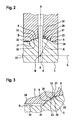
- FIG. 2 shown opened state of the valve in which the armature 3 abuts against the inner pole 2, resulting from the geometric configuration of the end faces 20, 30 of the inner pole 2 and armature 3, a first circular contact line 8 and a second circular contact line 9.
- the first cone portion 22 comes into contact with the spherical portion 31, and at the second contact line 9, the second taper portion 23 comes into contact with the spherical portion 31.
- a contact between the inner pole 2 and the armature 3 is limited to the two contact lines 8, 9. How farther FIGS. 2 and 3 can be seen, this results in between the two contact line 8, 9, a damping volume 10.
- the damping volume 10 includes in the contact case, a fuel and can thereby a robust damping at a high level provide, whereby a stop pulse is reduced. How out FIG. 3 it becomes clear that the damping volume 10 does not have to have a large volume, so that no additional space requirement results from the inventive design of the end faces 20, 30 of the inner pole 2 and the magnet armature 3.
- the two planar portions 24, 32 of the inner pole 2 and the magnet armature 3 are aligned parallel to each other and thereby perpendicular to the central axis XX.
- the gap S is provided such that even in the case of a slight tilting of the armature 2 from the central axis XX out no contact in the region of the plan regions 24, 32 occurs.
- Even with a slight tilting of the magnet armature 2 occur due to the inventive design of the end faces 20, 30, only two lines of contact. Although these contact lines in the tilted case of the magnet armature 3 are no longer concentric with the central axis XX, nevertheless the same advantages as with the designed concentric arrangement of the contact lines 8, 9 are obtained.
- the armature 3 further comprises a guide portion 33 on its radially outer side.
- the guide region 33 lies in a plane E, which is perpendicular to the central axis XX.
- plane E is also a center M of the spherical portion 31 of the armature 3.
- the radius R is in FIG. 2 located.
- a stop on two contact lines 8, 9 is provided.
- a damping volume 10 is defined between the two contact lines 8, 9 in the event of an attack.
- a magnetic bonding between the armature 3 and inner pole 2 can be reduced because only a minimal, two-line contact between the two components in case of attack is present.
- FIG. 4 shows a second embodiment of the invention, wherein identical or functionally identical parts are denoted by the same reference numerals as in the first embodiment.
- the inner pole 2 has a spherical region 25 and the magnet armature 3 a multi-cone 35 with a first cone portion 36 and a second cone portion 37.
- a damping volume 10 between the two end faces of the inner pole 2 and the armature 3 is obtained.
- two circular contact lines 8, 9 in case of attack which in FIG. 4 is shown.
- the valve of the second embodiment also has a guide element 11, which is arranged at the end of the valve needle 4.
- a guide opening 12 is provided, in which the guide element 11 is guided.
- valve needle 4 which is fixedly connected to the guide member 11 and the armature 3, guided in the interior of the inner pole 2.
Landscapes
- Engineering & Computer Science (AREA)
- General Engineering & Computer Science (AREA)
- Physics & Mathematics (AREA)
- Electromagnetism (AREA)
- Mechanical Engineering (AREA)
- Chemical & Material Sciences (AREA)
- Combustion & Propulsion (AREA)
- Magnetically Actuated Valves (AREA)
- Fuel-Injection Apparatus (AREA)
Claims (9)
- Soupape actionnée de manière électromagnétique pour la commande de fluides, comprenant:- un pôle intérieur (2) et- une armature d'aimant (3),- dans laquelle le pôle intérieur (2) présente un premier côté frontal (20) orienté vers l'armature d'aimant (3) et l'armature d'aimant (3) présente un deuxième côté frontal (30) orienté vers le pôle intérieur (2),- dans laquelle il se trouve entre le premier et le deuxième côtés frontaux (20, 30) une première ligne de contact (8) et une deuxième ligne de contact (9), lorsque le pôle intérieur (2) et l'armature d'aimant (3) se touchent, et- dans laquelle il se trouve un volume d'amortissement (10) entre la première et la deuxième lignes de contact (8, 9), lorsque le pôle intérieur et l'armature d'aimant se touchent,caractérisée en ce qu'un des côtés frontaux (20, 30) comprend un cône multiple et l'autre des côtés frontaux (20, 30) comprend une surface sphérique.
- Soupape selon la revendication 1, caractérisée en ce que la première et la deuxième lignes de contact (8, 9) est chaque fois une ligne circulaire, en particulier concentrique à un axe central (X-X) de la soupape.
- Soupape selon la revendication 1, caractérisée en ce que le premier côté frontal (20) du pôle intérieur (2) comprend un cône multiple (21) avec au moins une première région conique (22) et une deuxième région conique (23) et le deuxième côté frontal (30) de l'armature d'aimant (3) comprend une région sphérique (31).
- Soupape selon la revendication 1, caractérisée en ce que le premier côté frontal (20) du pôle intérieur comprend une région sphérique (25) et le deuxième côté frontal (30) de l'armature d'aimant (3) comprend au moins un cône multiple (35) avec une première région conique (36) et une deuxième région conique (37).
- Soupape selon l'une quelconque des revxendications précédentes, caractérisée en ce que le premier et le deuxième côtés frontaux (20, 30) comprennent chacun une région plane (24, 32), dans laquelle chaque région plane est perpendiculaire à un axe longitudinal (X-X) de la soupape.
- Soupape selon l'une quelconque des revendications précédentes, caractérisée en ce que le pôle intérieur (2) et l'armature d'aimant (3) se touchent exclusivement sur la première et la deuxième lignes de contact (8, 9).
- Soupape selon l'une quelconque des revendications précédentes, caractérisée en ce que la deuxième face frontale (30) de l'armature d'aimant (3) comprend une région sphérique (31) et l'armature d'aimant (3) présente une région de guidage (33), dans laquelle la région de guidage (33) est agencée dans un plan (E), qui est perpendiculaire à l'axe longitudinal (X-X) de la soupape et un point central (M) de la région sphérique est située dans le plan (E).
- Soupape selon l'une quelconque des revendications précédentes, caractérisée en ce que l'armature d'aimant (3) est reliée au pointeau (4) et le pointeau (4) est guidé dans le pôle intérieur (2).
- Soupape selon l'une quelconque des revendications précédentes, caractérisée en ce que le premier et le deuxième côtés frontaux (20, 30) du pôle intérieur (2) et de l'armature d'aimant (3) ne présentent pas de couche de protection contre l'usure.
Applications Claiming Priority (1)
| Application Number | Priority Date | Filing Date | Title |
|---|---|---|---|
| DE102013209672.0A DE102013209672A1 (de) | 2013-05-24 | 2013-05-24 | Elektromagnetisch betätigbares Ventil |
Publications (3)
| Publication Number | Publication Date |
|---|---|
| EP2806150A2 EP2806150A2 (fr) | 2014-11-26 |
| EP2806150A3 EP2806150A3 (fr) | 2014-12-03 |
| EP2806150B1 true EP2806150B1 (fr) | 2015-12-02 |
Family
ID=50434036
Family Applications (1)
| Application Number | Title | Priority Date | Filing Date |
|---|---|---|---|
| EP14163125.9A Not-in-force EP2806150B1 (fr) | 2013-05-24 | 2014-04-02 | Soupape actionnée de manière électromagnétique |
Country Status (3)
| Country | Link |
|---|---|
| US (1) | US9702475B2 (fr) |
| EP (1) | EP2806150B1 (fr) |
| DE (1) | DE102013209672A1 (fr) |
Families Citing this family (17)
| Publication number | Priority date | Publication date | Assignee | Title |
|---|---|---|---|---|
| US9113591B2 (en) | 2012-06-18 | 2015-08-25 | Raven Industries, Inc. | Implement for adjustably metering an agricultural field input according to different frame sections |
| US11160204B2 (en) | 2013-03-15 | 2021-11-02 | Raven Industries, Inc. | Localized product injection system for an agricultural sprayer |
| AU2014278310A1 (en) | 2013-06-10 | 2015-12-10 | Raven Industries, Inc. | Localized product injection system for an agricultural sprayer |
| US10173236B2 (en) | 2013-10-17 | 2019-01-08 | Raven Industries, Inc. | Nozzle control system and method |
| US9781916B2 (en) | 2013-10-17 | 2017-10-10 | Raven Industries, Inc. | Nozzle control system and method |
| DE102015209505A1 (de) * | 2015-05-22 | 2016-11-24 | Robert Bosch Gmbh | Kraftstoffinjektor |
| DE102015218768B3 (de) * | 2015-09-29 | 2017-03-02 | Continental Automotive Gmbh | Elektromagnetischer Aktor, elektromagnetisches Ventil und Kraftstoffhochdruckpumpe |
| DE102016203083A1 (de) * | 2016-02-26 | 2017-08-31 | Robert Bosch Gmbh | Magnetventil |
| KR101854982B1 (ko) * | 2016-06-13 | 2018-05-04 | 주식회사 현대케피코 | 소음 저감형 퍼지 제어 솔레노이드 밸브 |
| CN109891081B (zh) * | 2016-11-07 | 2021-01-19 | 三菱电机株式会社 | 燃料喷射阀 |
| WO2018129323A1 (fr) | 2017-01-05 | 2018-07-12 | Raven Industries, Inc. | Système d'injection de produit localisée et procédés associés |
| JP2018159294A (ja) * | 2017-03-22 | 2018-10-11 | 株式会社ケーヒン | 燃料噴射弁 |
| JP6788085B1 (ja) * | 2019-09-20 | 2020-11-18 | 株式会社ケーヒン | 電磁式燃料噴射弁 |
| US11612160B2 (en) | 2019-10-04 | 2023-03-28 | Raven Industries, Inc. | Valve control system and method |
| JP7326632B2 (ja) * | 2020-09-24 | 2023-08-15 | 日立Astemo株式会社 | 燃料噴射装置 |
| WO2022239329A1 (fr) * | 2021-05-12 | 2022-11-17 | 日立Astemo株式会社 | Dispositif d'injection de carburant |
| AU2022382950A1 (en) | 2021-11-05 | 2024-05-16 | Raven Industries, Inc. | Valve priming and depriming |
Family Cites Families (12)
| Publication number | Priority date | Publication date | Assignee | Title |
|---|---|---|---|---|
| US3168242A (en) * | 1962-11-05 | 1965-02-02 | Eldima A G | Electromagnetically operated temperature regulating system |
| DE19833461A1 (de) | 1998-07-24 | 2000-01-27 | Bosch Gmbh Robert | Elektromagnetisch betätigbares Ventil |
| US6994406B1 (en) * | 1998-12-16 | 2006-02-07 | Kelsey-Hayes Company | EHB proportional solenoid valve with stepped gap armature |
| DE10039083A1 (de) * | 2000-08-10 | 2002-02-21 | Bosch Gmbh Robert | Brennstoffeinspritzventil |
| US6853276B2 (en) * | 2001-09-20 | 2005-02-08 | Richard G. Smith | Electromagnetic formed contact surface |
| US7108242B2 (en) * | 2002-05-02 | 2006-09-19 | Continental Teves Ag & Co. Ohg | Seat valve |
| JP4064934B2 (ja) * | 2004-02-27 | 2008-03-19 | 三菱重工業株式会社 | 電磁弁装置 |
| JP4168448B2 (ja) * | 2004-07-08 | 2008-10-22 | 株式会社デンソー | 燃料噴射弁 |
| JP2007205234A (ja) * | 2006-02-01 | 2007-08-16 | Denso Corp | 燃料噴射弁 |
| JP5262972B2 (ja) * | 2009-05-08 | 2013-08-14 | 株式会社デンソー | 燃料噴射弁 |
| DE102010002229B4 (de) * | 2010-02-23 | 2022-07-21 | Robert Bosch Gmbh | Magnetventil zum Steuern eines Fluids |
| DE102010031275B4 (de) * | 2010-07-13 | 2023-12-14 | Robert Bosch Gmbh | Magnetventil mit Formfeder |
-
2013
- 2013-05-24 DE DE102013209672.0A patent/DE102013209672A1/de not_active Withdrawn
-
2014
- 2014-04-02 EP EP14163125.9A patent/EP2806150B1/fr not_active Not-in-force
- 2014-05-23 US US14/286,495 patent/US9702475B2/en not_active Expired - Fee Related
Also Published As
| Publication number | Publication date |
|---|---|
| DE102013209672A1 (de) | 2014-11-27 |
| EP2806150A2 (fr) | 2014-11-26 |
| EP2806150A3 (fr) | 2014-12-03 |
| US20140346382A1 (en) | 2014-11-27 |
| US9702475B2 (en) | 2017-07-11 |
Similar Documents
| Publication | Publication Date | Title |
|---|---|---|
| EP2806150A2 (fr) | Soupape actionnée de manière électromagnétique | |
| EP2901004B1 (fr) | Soupape d'injection | |
| EP2630016B1 (fr) | Électrovanne, système de freinage | |
| EP2634412B1 (fr) | Ventilateur d'injection | |
| EP2668392B1 (fr) | Injecteur muni d'un limiteur de débit | |
| EP3559437B1 (fr) | Soupape servant à doser un fluide | |
| DE102017218267A1 (de) | Fluidventil und Verfahren zur Steuerung der Zufuhr von Fluid | |
| WO2019037924A1 (fr) | Soupape proportionnelle servant à réguler un fluide gazeux | |
| AT500185A2 (de) | Mechanismus an einem elektromagnetischen ventil | |
| EP2742517B1 (fr) | Induit magnétique pour soupape d'injection | |
| EP1155231B1 (fr) | Soupape d'injection de carburant | |
| EP2628941B1 (fr) | Soupape d'injection de combustible | |
| EP3325862B1 (fr) | Électrovalve normalement fermée | |
| EP2519732B1 (fr) | Vanne de controle du debit de commande electrique, destinee en particulier a commander le debit d'une pompe haute pression a carburant | |
| WO2011160991A1 (fr) | Injecteur, en particulier injecteur pour rampe commune, et système d'injection de carburant présentant un injecteur | |
| DE102011078732A1 (de) | Vorrichtung zur Einspritzung von Kraftstoff | |
| WO2014139706A1 (fr) | Soupape de commande de fluide à étanchéité renforcée | |
| WO2019233662A1 (fr) | Soupape d'aspiration à commande électromagnétique et pompe à carburant haute pression | |
| EP3779172A1 (fr) | Soupape de dosage d'un fluide | |
| DE102015223043A1 (de) | Kraftstoff-Injektor | |
| WO2014206766A1 (fr) | Électrovanne et injecteur de carburant équipé d'une électrovanne | |
| EP2643619A1 (fr) | Soupape comportant un élément mobile cylindrique au moins par tronçons | |
| DE102015223166A1 (de) | Elektromagnetisch ansteuerbares Saugventil für eine Hochdruckpumpe, Hochdruckpumpe | |
| DE102016225769A1 (de) | Ventil zum Zumessen eines Fluids | |
| WO2016062594A1 (fr) | Injecteur de carburant |
Legal Events
| Date | Code | Title | Description |
|---|---|---|---|
| PUAL | Search report despatched |
Free format text: ORIGINAL CODE: 0009013 |
|
| PUAI | Public reference made under article 153(3) epc to a published international application that has entered the european phase |
Free format text: ORIGINAL CODE: 0009012 |
|
| 17P | Request for examination filed |
Effective date: 20140402 |
|
| AK | Designated contracting states |
Kind code of ref document: A2 Designated state(s): AL AT BE BG CH CY CZ DE DK EE ES FI FR GB GR HR HU IE IS IT LI LT LU LV MC MK MT NL NO PL PT RO RS SE SI SK SM TR |
|
| AX | Request for extension of the european patent |
Extension state: BA ME |
|
| AK | Designated contracting states |
Kind code of ref document: A3 Designated state(s): AL AT BE BG CH CY CZ DE DK EE ES FI FR GB GR HR HU IE IS IT LI LT LU LV MC MK MT NL NO PL PT RO RS SE SI SK SM TR |
|
| AX | Request for extension of the european patent |
Extension state: BA ME |
|
| RIC1 | Information provided on ipc code assigned before grant |
Ipc: F02M 51/06 20060101AFI20141024BHEP |
|
| R17P | Request for examination filed (corrected) |
Effective date: 20150603 |
|
| RBV | Designated contracting states (corrected) |
Designated state(s): AL AT BE BG CH CY CZ DE DK EE ES FI FR GB GR HR HU IE IS IT LI LT LU LV MC MK MT NL NO PL PT RO RS SE SI SK SM TR |
|
| GRAP | Despatch of communication of intention to grant a patent |
Free format text: ORIGINAL CODE: EPIDOSNIGR1 |
|
| RIC1 | Information provided on ipc code assigned before grant |
Ipc: F16K 31/06 20060101ALI20150715BHEP Ipc: F02M 51/06 20060101AFI20150715BHEP |
|
| INTG | Intention to grant announced |
Effective date: 20150820 |
|
| GRAS | Grant fee paid |
Free format text: ORIGINAL CODE: EPIDOSNIGR3 |
|
| GRAA | (expected) grant |
Free format text: ORIGINAL CODE: 0009210 |
|
| AK | Designated contracting states |
Kind code of ref document: B1 Designated state(s): AL AT BE BG CH CY CZ DE DK EE ES FI FR GB GR HR HU IE IS IT LI LT LU LV MC MK MT NL NO PL PT RO RS SE SI SK SM TR |
|
| REG | Reference to a national code |
Ref country code: GB Ref legal event code: FG4D Free format text: NOT ENGLISH |
|
| REG | Reference to a national code |
Ref country code: AT Ref legal event code: REF Ref document number: 763753 Country of ref document: AT Kind code of ref document: T Effective date: 20151215 Ref country code: CH Ref legal event code: EP |
|
| REG | Reference to a national code |
Ref country code: IE Ref legal event code: FG4D Free format text: LANGUAGE OF EP DOCUMENT: GERMAN |
|
| REG | Reference to a national code |
Ref country code: DE Ref legal event code: R096 Ref document number: 502014000205 Country of ref document: DE |
|
| REG | Reference to a national code |
Ref country code: NL Ref legal event code: MP Effective date: 20160302 |
|
| REG | Reference to a national code |
Ref country code: LT Ref legal event code: MG4D |
|
| REG | Reference to a national code |
Ref country code: FR Ref legal event code: PLFP Year of fee payment: 3 |
|
| PG25 | Lapsed in a contracting state [announced via postgrant information from national office to epo] |
Ref country code: LT Free format text: LAPSE BECAUSE OF FAILURE TO SUBMIT A TRANSLATION OF THE DESCRIPTION OR TO PAY THE FEE WITHIN THE PRESCRIBED TIME-LIMIT Effective date: 20151202 Ref country code: ES Free format text: LAPSE BECAUSE OF FAILURE TO SUBMIT A TRANSLATION OF THE DESCRIPTION OR TO PAY THE FEE WITHIN THE PRESCRIBED TIME-LIMIT Effective date: 20151202 Ref country code: NO Free format text: LAPSE BECAUSE OF FAILURE TO SUBMIT A TRANSLATION OF THE DESCRIPTION OR TO PAY THE FEE WITHIN THE PRESCRIBED TIME-LIMIT Effective date: 20160302 |
|
| PG25 | Lapsed in a contracting state [announced via postgrant information from national office to epo] |
Ref country code: NL Free format text: LAPSE BECAUSE OF FAILURE TO SUBMIT A TRANSLATION OF THE DESCRIPTION OR TO PAY THE FEE WITHIN THE PRESCRIBED TIME-LIMIT Effective date: 20151202 Ref country code: RS Free format text: LAPSE BECAUSE OF FAILURE TO SUBMIT A TRANSLATION OF THE DESCRIPTION OR TO PAY THE FEE WITHIN THE PRESCRIBED TIME-LIMIT Effective date: 20151202 Ref country code: FI Free format text: LAPSE BECAUSE OF FAILURE TO SUBMIT A TRANSLATION OF THE DESCRIPTION OR TO PAY THE FEE WITHIN THE PRESCRIBED TIME-LIMIT Effective date: 20151202 Ref country code: PL Free format text: LAPSE BECAUSE OF FAILURE TO SUBMIT A TRANSLATION OF THE DESCRIPTION OR TO PAY THE FEE WITHIN THE PRESCRIBED TIME-LIMIT Effective date: 20151202 Ref country code: SE Free format text: LAPSE BECAUSE OF FAILURE TO SUBMIT A TRANSLATION OF THE DESCRIPTION OR TO PAY THE FEE WITHIN THE PRESCRIBED TIME-LIMIT Effective date: 20151202 Ref country code: LV Free format text: LAPSE BECAUSE OF FAILURE TO SUBMIT A TRANSLATION OF THE DESCRIPTION OR TO PAY THE FEE WITHIN THE PRESCRIBED TIME-LIMIT Effective date: 20151202 Ref country code: GR Free format text: LAPSE BECAUSE OF FAILURE TO SUBMIT A TRANSLATION OF THE DESCRIPTION OR TO PAY THE FEE WITHIN THE PRESCRIBED TIME-LIMIT Effective date: 20160303 |
|
| PG25 | Lapsed in a contracting state [announced via postgrant information from national office to epo] |
Ref country code: IS Free format text: LAPSE BECAUSE OF FAILURE TO SUBMIT A TRANSLATION OF THE DESCRIPTION OR TO PAY THE FEE WITHIN THE PRESCRIBED TIME-LIMIT Effective date: 20151202 |
|
| PG25 | Lapsed in a contracting state [announced via postgrant information from national office to epo] |
Ref country code: CZ Free format text: LAPSE BECAUSE OF FAILURE TO SUBMIT A TRANSLATION OF THE DESCRIPTION OR TO PAY THE FEE WITHIN THE PRESCRIBED TIME-LIMIT Effective date: 20151202 |
|
| PG25 | Lapsed in a contracting state [announced via postgrant information from national office to epo] |
Ref country code: EE Free format text: LAPSE BECAUSE OF FAILURE TO SUBMIT A TRANSLATION OF THE DESCRIPTION OR TO PAY THE FEE WITHIN THE PRESCRIBED TIME-LIMIT Effective date: 20151202 Ref country code: BE Free format text: LAPSE BECAUSE OF NON-PAYMENT OF DUE FEES Effective date: 20160430 Ref country code: IS Free format text: LAPSE BECAUSE OF FAILURE TO SUBMIT A TRANSLATION OF THE DESCRIPTION OR TO PAY THE FEE WITHIN THE PRESCRIBED TIME-LIMIT Effective date: 20160402 Ref country code: PT Free format text: LAPSE BECAUSE OF FAILURE TO SUBMIT A TRANSLATION OF THE DESCRIPTION OR TO PAY THE FEE WITHIN THE PRESCRIBED TIME-LIMIT Effective date: 20160404 Ref country code: SK Free format text: LAPSE BECAUSE OF FAILURE TO SUBMIT A TRANSLATION OF THE DESCRIPTION OR TO PAY THE FEE WITHIN THE PRESCRIBED TIME-LIMIT Effective date: 20151202 Ref country code: SM Free format text: LAPSE BECAUSE OF FAILURE TO SUBMIT A TRANSLATION OF THE DESCRIPTION OR TO PAY THE FEE WITHIN THE PRESCRIBED TIME-LIMIT Effective date: 20151202 Ref country code: RO Free format text: LAPSE BECAUSE OF FAILURE TO SUBMIT A TRANSLATION OF THE DESCRIPTION OR TO PAY THE FEE WITHIN THE PRESCRIBED TIME-LIMIT Effective date: 20151202 |
|
| REG | Reference to a national code |
Ref country code: DE Ref legal event code: R097 Ref document number: 502014000205 Country of ref document: DE |
|
| PLBE | No opposition filed within time limit |
Free format text: ORIGINAL CODE: 0009261 |
|
| STAA | Information on the status of an ep patent application or granted ep patent |
Free format text: STATUS: NO OPPOSITION FILED WITHIN TIME LIMIT |
|
| PG25 | Lapsed in a contracting state [announced via postgrant information from national office to epo] |
Ref country code: DK Free format text: LAPSE BECAUSE OF FAILURE TO SUBMIT A TRANSLATION OF THE DESCRIPTION OR TO PAY THE FEE WITHIN THE PRESCRIBED TIME-LIMIT Effective date: 20151202 |
|
| 26N | No opposition filed |
Effective date: 20160905 |
|
| PG25 | Lapsed in a contracting state [announced via postgrant information from national office to epo] |
Ref country code: SI Free format text: LAPSE BECAUSE OF FAILURE TO SUBMIT A TRANSLATION OF THE DESCRIPTION OR TO PAY THE FEE WITHIN THE PRESCRIBED TIME-LIMIT Effective date: 20151202 |
|
| PG25 | Lapsed in a contracting state [announced via postgrant information from national office to epo] |
Ref country code: LU Free format text: LAPSE BECAUSE OF FAILURE TO SUBMIT A TRANSLATION OF THE DESCRIPTION OR TO PAY THE FEE WITHIN THE PRESCRIBED TIME-LIMIT Effective date: 20160402 |
|
| REG | Reference to a national code |
Ref country code: IE Ref legal event code: MM4A |
|
| REG | Reference to a national code |
Ref country code: FR Ref legal event code: PLFP Year of fee payment: 4 |
|
| PG25 | Lapsed in a contracting state [announced via postgrant information from national office to epo] |
Ref country code: IE Free format text: LAPSE BECAUSE OF NON-PAYMENT OF DUE FEES Effective date: 20160402 |
|
| PGFP | Annual fee paid to national office [announced via postgrant information from national office to epo] |
Ref country code: FR Payment date: 20170424 Year of fee payment: 4 |
|
| PGFP | Annual fee paid to national office [announced via postgrant information from national office to epo] |
Ref country code: IT Payment date: 20170430 Year of fee payment: 4 |
|
| REG | Reference to a national code |
Ref country code: CH Ref legal event code: PL |
|
| PG25 | Lapsed in a contracting state [announced via postgrant information from national office to epo] |
Ref country code: CH Free format text: LAPSE BECAUSE OF NON-PAYMENT OF DUE FEES Effective date: 20170430 Ref country code: LI Free format text: LAPSE BECAUSE OF NON-PAYMENT OF DUE FEES Effective date: 20170430 |
|
| PG25 | Lapsed in a contracting state [announced via postgrant information from national office to epo] |
Ref country code: HU Free format text: LAPSE BECAUSE OF FAILURE TO SUBMIT A TRANSLATION OF THE DESCRIPTION OR TO PAY THE FEE WITHIN THE PRESCRIBED TIME-LIMIT; INVALID AB INITIO Effective date: 20140402 |
|
| PG25 | Lapsed in a contracting state [announced via postgrant information from national office to epo] |
Ref country code: MC Free format text: LAPSE BECAUSE OF FAILURE TO SUBMIT A TRANSLATION OF THE DESCRIPTION OR TO PAY THE FEE WITHIN THE PRESCRIBED TIME-LIMIT Effective date: 20151202 Ref country code: MT Free format text: LAPSE BECAUSE OF FAILURE TO SUBMIT A TRANSLATION OF THE DESCRIPTION OR TO PAY THE FEE WITHIN THE PRESCRIBED TIME-LIMIT Effective date: 20151202 Ref country code: MK Free format text: LAPSE BECAUSE OF FAILURE TO SUBMIT A TRANSLATION OF THE DESCRIPTION OR TO PAY THE FEE WITHIN THE PRESCRIBED TIME-LIMIT Effective date: 20151202 Ref country code: HR Free format text: LAPSE BECAUSE OF FAILURE TO SUBMIT A TRANSLATION OF THE DESCRIPTION OR TO PAY THE FEE WITHIN THE PRESCRIBED TIME-LIMIT Effective date: 20151202 Ref country code: CY Free format text: LAPSE BECAUSE OF FAILURE TO SUBMIT A TRANSLATION OF THE DESCRIPTION OR TO PAY THE FEE WITHIN THE PRESCRIBED TIME-LIMIT Effective date: 20151202 |
|
| PG25 | Lapsed in a contracting state [announced via postgrant information from national office to epo] |
Ref country code: BG Free format text: LAPSE BECAUSE OF FAILURE TO SUBMIT A TRANSLATION OF THE DESCRIPTION OR TO PAY THE FEE WITHIN THE PRESCRIBED TIME-LIMIT Effective date: 20151202 |
|
| PG25 | Lapsed in a contracting state [announced via postgrant information from national office to epo] |
Ref country code: TR Free format text: LAPSE BECAUSE OF FAILURE TO SUBMIT A TRANSLATION OF THE DESCRIPTION OR TO PAY THE FEE WITHIN THE PRESCRIBED TIME-LIMIT Effective date: 20151202 Ref country code: AL Free format text: LAPSE BECAUSE OF FAILURE TO SUBMIT A TRANSLATION OF THE DESCRIPTION OR TO PAY THE FEE WITHIN THE PRESCRIBED TIME-LIMIT Effective date: 20151202 |
|
| GBPC | Gb: european patent ceased through non-payment of renewal fee |
Effective date: 20180402 |
|
| PG25 | Lapsed in a contracting state [announced via postgrant information from national office to epo] |
Ref country code: GB Free format text: LAPSE BECAUSE OF NON-PAYMENT OF DUE FEES Effective date: 20180402 |
|
| PG25 | Lapsed in a contracting state [announced via postgrant information from national office to epo] |
Ref country code: FR Free format text: LAPSE BECAUSE OF NON-PAYMENT OF DUE FEES Effective date: 20180430 Ref country code: IT Free format text: LAPSE BECAUSE OF NON-PAYMENT OF DUE FEES Effective date: 20180402 |
|
| REG | Reference to a national code |
Ref country code: AT Ref legal event code: MM01 Ref document number: 763753 Country of ref document: AT Kind code of ref document: T Effective date: 20190402 |
|
| PG25 | Lapsed in a contracting state [announced via postgrant information from national office to epo] |
Ref country code: AT Free format text: LAPSE BECAUSE OF NON-PAYMENT OF DUE FEES Effective date: 20190402 |
|
| PGFP | Annual fee paid to national office [announced via postgrant information from national office to epo] |
Ref country code: DE Payment date: 20230627 Year of fee payment: 10 |
|
| REG | Reference to a national code |
Ref country code: DE Ref legal event code: R119 Ref document number: 502014000205 Country of ref document: DE |
|
| PG25 | Lapsed in a contracting state [announced via postgrant information from national office to epo] |
Ref country code: DE Free format text: LAPSE BECAUSE OF NON-PAYMENT OF DUE FEES Effective date: 20241105 |
|
| PG25 | Lapsed in a contracting state [announced via postgrant information from national office to epo] |
Ref country code: DE Free format text: LAPSE BECAUSE OF NON-PAYMENT OF DUE FEES Effective date: 20241105 |