EP2806259A1 - Fixation de montage de capteur - Google Patents
Fixation de montage de capteur Download PDFInfo
- Publication number
- EP2806259A1 EP2806259A1 EP13169171.9A EP13169171A EP2806259A1 EP 2806259 A1 EP2806259 A1 EP 2806259A1 EP 13169171 A EP13169171 A EP 13169171A EP 2806259 A1 EP2806259 A1 EP 2806259A1
- Authority
- EP
- European Patent Office
- Prior art keywords
- mounting
- sensor
- environment
- attachment
- resilient member
- Prior art date
- Legal status (The legal status is an assumption and is not a legal conclusion. Google has not performed a legal analysis and makes no representation as to the accuracy of the status listed.)
- Granted
Links
Images
Classifications
-
- F—MECHANICAL ENGINEERING; LIGHTING; HEATING; WEAPONS; BLASTING
- F16—ENGINEERING ELEMENTS AND UNITS; GENERAL MEASURES FOR PRODUCING AND MAINTAINING EFFECTIVE FUNCTIONING OF MACHINES OR INSTALLATIONS; THERMAL INSULATION IN GENERAL
- F16F—SPRINGS; SHOCK-ABSORBERS; MEANS FOR DAMPING VIBRATION
- F16F9/00—Springs, vibration-dampers, shock-absorbers, or similarly-constructed movement-dampers using a fluid or the equivalent as damping medium
- F16F9/32—Details
-
- G—PHYSICS
- G01—MEASURING; TESTING
- G01L—MEASURING FORCE, STRESS, TORQUE, WORK, MECHANICAL POWER, MECHANICAL EFFICIENCY, OR FLUID PRESSURE
- G01L23/00—Devices or apparatus for measuring or indicating or recording rapid changes, such as oscillations, in the pressure of steam, gas, or liquid; Indicators for determining work or energy of steam, internal-combustion, or other fluid-pressure engines from the condition of the working fluid
- G01L23/26—Details or accessories
-
- F—MECHANICAL ENGINEERING; LIGHTING; HEATING; WEAPONS; BLASTING
- F16—ENGINEERING ELEMENTS AND UNITS; GENERAL MEASURES FOR PRODUCING AND MAINTAINING EFFECTIVE FUNCTIONING OF MACHINES OR INSTALLATIONS; THERMAL INSULATION IN GENERAL
- F16M—FRAMES, CASINGS OR BEDS OF ENGINES, MACHINES OR APPARATUS, NOT SPECIFIC TO ENGINES, MACHINES OR APPARATUS PROVIDED FOR ELSEWHERE; STANDS; SUPPORTS
- F16M13/00—Other supports for positioning apparatus or articles; Means for steadying hand-held apparatus or articles
- F16M13/02—Other supports for positioning apparatus or articles; Means for steadying hand-held apparatus or articles for supporting on, or attaching to, an object, e.g. tree, gate, window-frame, cycle
Definitions
- the present disclosure relates to mounting attachments, and, more particularly, to a mounting attachment for mounting a sensor to an object or environment, such as, combustion chambers of gas turbines.
- the sensor may primarily be adapted to a threaded plug; further the threaded plug may be positioned through a hole in the object or environment to secure the sensor appropriately in the object or environment by utilizing a suitable sensor adaptor.
- the threaded plug is threadably tighten against the sensor adaptor having the sensor enabling the sensor's tip to be securely communicate with the object or environment for measuring or detecting various physical parameters therewithin.
- the sensor is held in the position by threadably securement that applies the required mounting torque.
- this mounting torque is quite small, which may lead to loosening of the threaded plug form the sensor adaptor thereby loosening the sensor.
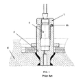
- FIG. 1 depicts a typical arrangement of described conventional senor placement, where the sensor is depicted by 'S,' the threaded plug is depicted by 'T,' the adaptor is depicted by 'A,' the spot weld is depicted by the 'W,' and the environment is depicted by the 'E.'
- the present disclosure describes a mounting attachment for positioning a sensor in an environment, like a combustion chamber of a gas turbine, that will be presented in the following simplified summary to provide a basic understanding of one or more aspects of the disclosure that are intended to overcome the discussed drawbacks, but to include all advantages thereof, along with providing some additional advantages.
- This summary is not an extensive overview of the disclosure. It is intended to neither identify key or critical elements of the disclosure, nor to delineate the scope of the present disclosure. Rather, the sole purpose of this summary is to present some concepts of the disclosure, its aspects and advantages in a simplified form as a prelude to the more detailed description that is presented hereinafter.
- An object of the present disclosure is to describe a mounting attachment, which may be adaptable in terms of securing a sensor in proper manner that may prevent the loosening thereof, and at the same time, the sensor may be easily accessible and replaceable, when required, from the object or environment.
- the object is to preclude spot welding that is conventionally required to maintain a mounting torque to secure the sensor is a position.
- Another object of the present disclosure is to describe a mounting attachment, which is convenient to use in an effective and economical way.
- a mounting attachment for positioning a sensor, such as a pulsation sensor, in an environment.
- a sensor such as a pulsation sensor
- Example of the environment, where such attachment may be utilized including but not limited to, a combustion chamber of a gas turbine. While the disclosure will be described in conjunction to the combustion chamber of a gas turbine for the purpose of better understanding, the scope of the disclosure will extend to all such components where the present mounting attachment may be successfully utilized.
- a mounting attachment for positioning a sensor in an environment.
- the mounting attachment includes a mounting member and at least one primary resilient member.
- the mounting member has a hollow elongated configuration for incorporating the sensor therewithin.
- the mounting member includes a first end portion, a second end portion and a third portion between the first and second end portions.
- the first end portion includes a shoulder member projecting radially inward.
- the second end portion includes internally configured threads to threadably screw the mounting member to a counterpart thereof within the environment, configuring the sensor to an adaptor within the environment to measure variable physical parameters within the environment.
- the third portion having a flange member projecting radially inward.
- the sensor extends within the mounting member from the first end portion to the second end portion, being engaged at the shoulder member and the flange member.
- the at least one primary resilient member is disposed within the mounting member secularly between the shoulder member and the flange member, in a coordinating manner with the sensor.
- the at least one primary resilient member applies an axially outward force on the mounting member to prevent thereto from loosening from the counterpart, and providing a mounting torque for mounting the sensor at a target position within the environment.
- the at least one primary resilient member exhibits stiffness corresponding to the mounting torque required for mounting the sensor.
- the at least one primary resilient member may be a helical spring.
- the mountable attachment may further include a sealing plate having a through recess to receive the mounting member to partially expose thereto with the environment and further for sealing the environment.
- the mounting member may also include a flange member projecting radially outward and configured proximate to the first end portion thereof.
- the mountable attachment may also include at least one secondary resilient member for partially receiving the mounting member and secularly resting between the sealing plate and the flange member.
- the at least one secondary resilient member has a higher stiffness than the at least one primary resilient member.
- the at least one primary and secondary resilient members are capable of attaining a resulting mounting force to prevent thereto from loosening from the counterpart.
- the at least one secondary resilient member may also be a helical spring.
- FIG. 1 illustrates a conventional arrangement for securing a sensor to an environment, such as a combustion chamber of a gas turbine;
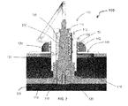
- FIG. 2 illustrates a sectional front view of a mountable attachment with an environment, such as a combustion chamber of a gas turbine, in accordance with an exemplary embodiment of the present disclosure
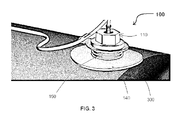
- FIG. 3 illustrates a perspective view of the mountable attachment of FIG. 2 , in accordance with an exemplary embodiment of the present disclosure.
- FIGS. 2 and 3 examples of a mountable attachment 100 for or positioning a sensor 200 in an environment 300, illustrated in accordance with an exemplary embodiment of the present disclosure.
- Example of the environment 300, where such attachment 100 may be utilized including but not limited to, a combustion chamber of a gas turbine. While the disclosure will be described in conjunction to the combustion chamber of the gas turbine, and will be designated with number 300, for the purpose of better understanding, the scope of the disclosure will extend to all such components where the present mountable attachment 100 may be successfully utilized.
- the mountable attachment 100 includes a mounting member 110, which is hollow and is elongated, i.e. have a suitable length thereof, in its configuration.
- the mounting member 110 has a first end portion 112, a second end portion 116, and a third portion 120 between the first and second end portions 112 and 116.
- the first end portion 112 is designed to include a shoulder member 114, which projects radially inward from the first end portion 112.
- the second end portion 116 includes internally configured threads 118 to threadably screw the mounting member 110 to a counterpart 310 thereof within the environment 300.
- the third portion 120 also includes a flange member 122, which projects radially inward from the hollow elongated mounting member 110.
- the mountable attachment 100 also includes at least one primary resilient member 130, which is adapted to be disposed within the mounting member 110. As shown in FIG. 2 , only one primary resilient member 130 is disposed with the mounting member 110, however, without departing from the scope of the present disclosure more than one such primary resilient member 130 may be provided depending upon the requirement of the mountable attachment 100.
- the mounting member 110 and the primary resilient member 130 are adapted to secure the sensor 200 within the mountable attachment 100 for positioning the sensor 200 within the combustion chamber 300 of the gas turbine.
- the hollow and elongated configuration of the mounting member 110 enables incorporation of the sensor 200 therewithin.
- the second end portion 116 that includes the internally configured threads 118 threadably screw the mounting member 110 to the counterpart 310 within the combustion chamber 300, which in turn enables configuring of the sensor 200 within the combustion chamber 300 by utilizing a suitable adaptor 320.
- the sensor 200 is adapted to be configured within the hollow elongated mounting member 110 in a manner that extends within the mounting member 110 from the first end portion 112 to the second end portion 116, being engaged at the shoulder member 114 and the flange member 122.
- the primary resilient member 130 is also secularly disposed between the shoulder member 114 and the flange member 122 within the mounting member 110, in a coordinating manner with the sensor 200.
- there may be various primary resilient members 130 which may be arranged around the sensors 200.
- there may be various other arrangements between the primary resilient member 130 and the sensor 200 In FIG. 2 , the example arrangement between the primary resilient member 130 and the sensor 200 is illustrated where the resilient member 130 is depicted to partially encapsulate the sensor 200, and will be described herein with that regard.
- the primary resilient member 130 applies an axially outward force (as shown by arrow 'X' in FIG. 2 ) on the mounting member 110 to prevent thereto from loosening from the counterpart 310, and providing a mounting torque for mounting the sensor 200 at a target position within the combustion chamber 300.
- the primary resilient member 130 may exhibit stiffness corresponding to the mounting torque required for mounting the sensor 200 at the target position. No matter how tighten the mounting member 110 is screwed on its counterpart 310, the sensor 200 only gets required mounting torque defined by the stiffness of the primary resilient member 130 for placing the sensor 200 at the targeted position.
- the target position may a position where the sensor 200 is maintained in close coordination with the adaptor 320 or the combustion chamber 300 for measuring variable physical parameters within the combustion chamber 300.
- the mountable attachment 100 may also additionally include at least one secondary resilient member 150, which may in combination with the primary resilient member 130 attain a resulting mounting force to prevent thereto from loosening from the counterpart 310, in a scenario where the primary resilient member 130 may lag in any manner.
- the secondary resilient member 150 also applies an axially outward force (as shown by arrow 'X' in FIG. 2 ) for attaining the resulting mounting force to the said purpose.
- the hollow elongated mounting member 100 further includes a flange member 124 projecting radially outward proximate to the first end portion 112.
- the mountable attachment 100 also includes a sealing plate 140, which is combination with the flange member 124 secures the secondary resilient member 150.
- the sealing plate 140 includes a through recess 142 to receive the hollow elongated mounting member 110 to partially expose thereto with the combustion chamber 300 and further sealing the combustion chamber 300.
- the secondary resilient member 150 partially receives the mounting member 110 and secularly rests between the sealing plate 140 and the flange member 124.
- the secondary resilient member 150 has a higher stiffness than the primary resilient member 130 resulting higher torque on the threads 118 to prevent the mounting member 110 from loosening. As shown in FIGS. 2 and 3 , only one secondary resilient member 150 is provided, however, without departing from the scope of the present disclosure more than one such secondary resilient member 150 may be configured depending upon the requirement.
- the primary resilient member 130 and the secondary resilient member 150 are helical springs, however, without departing from the scope of the present disclosure the resilient members may any other biasing member of arrangement that are capable of exhibiting required mounting torque for positioning the sensor 200 in the targeted position within the combustion chamber 300.
- a suitable wiring and electronic system may be coupled to the sensor 200 for analysis of the data measured or detected by the sensor 200.
- a mountable attachment such as the mountable attachment 100, for or positioning a sensor in an environment, such as a combustion chamber of a gas turbine, of the present disclosure are advantageous in various scopes.
- the mounting attachment is adaptable in terms of securing the sensor in proper manner that may prevent the loosening thereof, and at the same time, the sensor may be easily accessible and replaceable, when required, from the object or environment.
- the mountable attachment precludes spot welding that is conventionally required to maintain a mounting torque to secure the sensor is a position.
- the mounting attachment is capable of being mounted from outside the environment, such as an engine without the requirement of secure spot or any other weld in convenient, effective and economical way.
Landscapes
- Engineering & Computer Science (AREA)
- General Engineering & Computer Science (AREA)
- Mechanical Engineering (AREA)
- Chemical & Material Sciences (AREA)
- Combustion & Propulsion (AREA)
- Physics & Mathematics (AREA)
- General Physics & Mathematics (AREA)
- Measuring Fluid Pressure (AREA)
- Testing Or Calibration Of Command Recording Devices (AREA)
Priority Applications (5)
| Application Number | Priority Date | Filing Date | Title |
|---|---|---|---|
| EP13169171.9A EP2806259B1 (fr) | 2013-05-24 | 2013-05-24 | Fixation de montage de capteur |
| US14/273,840 US9429206B2 (en) | 2013-05-24 | 2014-05-09 | Sensor mounting attachment |
| KR1020140059506A KR101584976B1 (ko) | 2013-05-24 | 2014-05-19 | 센서 장착 어태치먼트 |
| CN201410220957.7A CN104180835B (zh) | 2013-05-24 | 2014-05-23 | 传感器安装附件 |
| JP2014108057A JP5800955B2 (ja) | 2013-05-24 | 2014-05-26 | センサ取付アタッチメント |
Applications Claiming Priority (1)
| Application Number | Priority Date | Filing Date | Title |
|---|---|---|---|
| EP13169171.9A EP2806259B1 (fr) | 2013-05-24 | 2013-05-24 | Fixation de montage de capteur |
Publications (2)
| Publication Number | Publication Date |
|---|---|
| EP2806259A1 true EP2806259A1 (fr) | 2014-11-26 |
| EP2806259B1 EP2806259B1 (fr) | 2019-08-14 |
Family
ID=48482959
Family Applications (1)
| Application Number | Title | Priority Date | Filing Date |
|---|---|---|---|
| EP13169171.9A Active EP2806259B1 (fr) | 2013-05-24 | 2013-05-24 | Fixation de montage de capteur |
Country Status (5)
| Country | Link |
|---|---|
| US (1) | US9429206B2 (fr) |
| EP (1) | EP2806259B1 (fr) |
| JP (1) | JP5800955B2 (fr) |
| KR (1) | KR101584976B1 (fr) |
| CN (1) | CN104180835B (fr) |
Families Citing this family (2)
| Publication number | Priority date | Publication date | Assignee | Title |
|---|---|---|---|---|
| CA3081575A1 (fr) * | 2017-11-14 | 2019-05-23 | Hexagon Technology As | Systeme de montage de capteur |
| CN113758523A (zh) * | 2021-09-06 | 2021-12-07 | 盐城市聚云网络科技有限公司 | 一种便于多组安装的智能机器信息传感器 |
Citations (1)
| Publication number | Priority date | Publication date | Assignee | Title |
|---|---|---|---|---|
| DE202007001606U1 (de) * | 2007-02-03 | 2007-04-05 | Parker Hannifin Gmbh & Co. Kg | Druckmessvorrichtung für Motorblöcke von Kraftfahrzeugen |
Family Cites Families (12)
| Publication number | Priority date | Publication date | Assignee | Title |
|---|---|---|---|---|
| US4955441A (en) * | 1989-09-26 | 1990-09-11 | Toledo Scale Corporation | Load cell mounting for rotational control |
| US5807048A (en) * | 1992-09-03 | 1998-09-15 | European Atomic Energy Community (Euratom) | Sealing fastener with ultrasonic identifier and removal attempt indicator, and ultrasonic reading device for same |
| US5369952A (en) * | 1993-07-20 | 1994-12-06 | General Electric Company | Variable friction force damper |
| JPH07260602A (ja) * | 1994-03-25 | 1995-10-13 | Smc Corp | センサ |
| US5765436A (en) | 1997-05-23 | 1998-06-16 | Wilda; Douglas W. | Meter body for pressure transmitter |
| JP4909066B2 (ja) | 2003-02-05 | 2012-04-04 | キストラー ホールディング アクチエンゲゼルシャフト | 初期応力デバイスを備える測定センサ |
| JP4777816B2 (ja) | 2005-03-31 | 2011-09-21 | 長野計器株式会社 | 差圧測定用の均圧弁、および、差圧式流量計 |
| US8042402B2 (en) * | 2008-05-01 | 2011-10-25 | General Electric Company | Modular sensor assembly |
| CN201239862Y (zh) * | 2008-05-28 | 2009-05-20 | 如冈自动化控制技术(上海)有限公司 | 坡口焊割机器手夹具 |
| CN201548196U (zh) * | 2009-11-20 | 2010-08-11 | 北京遥测技术研究所 | 一种动态间隙测量传感器 |
| US20120096961A1 (en) | 2010-10-21 | 2012-04-26 | General Electric Company | Probe holder for turbine engine sensor |
| US8347698B2 (en) | 2010-10-21 | 2013-01-08 | General Electric Company | Sensor with G-load absorbing shoulder |
-
2013
- 2013-05-24 EP EP13169171.9A patent/EP2806259B1/fr active Active
-
2014
- 2014-05-09 US US14/273,840 patent/US9429206B2/en active Active
- 2014-05-19 KR KR1020140059506A patent/KR101584976B1/ko not_active Expired - Fee Related
- 2014-05-23 CN CN201410220957.7A patent/CN104180835B/zh active Active
- 2014-05-26 JP JP2014108057A patent/JP5800955B2/ja not_active Expired - Fee Related
Patent Citations (1)
| Publication number | Priority date | Publication date | Assignee | Title |
|---|---|---|---|---|
| DE202007001606U1 (de) * | 2007-02-03 | 2007-04-05 | Parker Hannifin Gmbh & Co. Kg | Druckmessvorrichtung für Motorblöcke von Kraftfahrzeugen |
Also Published As
| Publication number | Publication date |
|---|---|
| US9429206B2 (en) | 2016-08-30 |
| EP2806259B1 (fr) | 2019-08-14 |
| KR20140138038A (ko) | 2014-12-03 |
| CN104180835B (zh) | 2017-01-04 |
| JP5800955B2 (ja) | 2015-10-28 |
| JP2014232106A (ja) | 2014-12-11 |
| US20140346313A1 (en) | 2014-11-27 |
| KR101584976B1 (ko) | 2016-01-13 |
| CN104180835A (zh) | 2014-12-03 |
Similar Documents
| Publication | Publication Date | Title |
|---|---|---|
| US9341522B2 (en) | Spring-loaded temperature sensor | |
| US10041532B2 (en) | Sensor device with mounting means | |
| US20080000465A1 (en) | Adaptor for device mount | |
| EP2749853A3 (fr) | Système et procédé de surveillance multi-modale de l'état d'un liquide | |
| IL206546A (en) | Additive to cartridge | |
| US9429206B2 (en) | Sensor mounting attachment | |
| JP2014529071A (ja) | 振動低減および/または改善スリーブを含む排気ガス温度センサ | |
| GB2550908A (en) | Engine data logger | |
| JP2013533429A (ja) | 排気ガスターボチャージャ | |
| SE1551480A1 (sv) | Fastsättningsdon för en elektronisk komponent, i synnerhet en accelerationssensor för airbagsystem | |
| WO2014143824A8 (fr) | Plateforme multimodale de capteur d'état de fluide et système associé | |
| RU2016151170A (ru) | Устройство крепления датчика для гидравлического цилиндра | |
| EP3933905A4 (fr) | Boîtier de montage d'élément optique, dispositif électronique et module électronique | |
| FR3071811B1 (fr) | Systeme de fixation d'un ecran sous caisse de vehicule automobile | |
| US20160178480A1 (en) | Crankshaft position sensing system | |
| MY185684A (en) | Device for attaching ballistic protection elements | |
| US20160069923A1 (en) | Wheel speed sensor | |
| CN104634230A (zh) | 一种柴油机配气相位的辅助检测装置及其检测方法 | |
| RU2747441C1 (ru) | Инерциальный блок с подвесным инерциальным устройством | |
| US20180372204A1 (en) | Differential Bearing Arrangement For Mounting A Differential Cage | |
| CN104023497A (zh) | 用于车辆的电子控制单元 | |
| US9513154B2 (en) | Connector mounting structure, mounting-result inspection tool, and mounting-result inspection method | |
| JP2012167624A (ja) | エンジン組立装置及びエンジン組立方法 | |
| US20200249333A1 (en) | Sensor mounting device, sensor assembly and vehicle | |
| KR20200087164A (ko) | 차량용 센서 유닛 |
Legal Events
| Date | Code | Title | Description |
|---|---|---|---|
| PUAI | Public reference made under article 153(3) epc to a published international application that has entered the european phase |
Free format text: ORIGINAL CODE: 0009012 |
|
| 17P | Request for examination filed |
Effective date: 20130524 |
|
| AK | Designated contracting states |
Kind code of ref document: A1 Designated state(s): AL AT BE BG CH CY CZ DE DK EE ES FI FR GB GR HR HU IE IS IT LI LT LU LV MC MK MT NL NO PL PT RO RS SE SI SK SM TR |
|
| AX | Request for extension of the european patent |
Extension state: BA ME |
|
| R17P | Request for examination filed (corrected) |
Effective date: 20150519 |
|
| RBV | Designated contracting states (corrected) |
Designated state(s): AL AT BE BG CH CY CZ DE DK EE ES FI FR GB GR HR HU IE IS IT LI LT LU LV MC MK MT NL NO PL PT RO RS SE SI SK SM TR |
|
| RAP1 | Party data changed (applicant data changed or rights of an application transferred) |
Owner name: GENERAL ELECTRIC TECHNOLOGY GMBH |
|
| RAP1 | Party data changed (applicant data changed or rights of an application transferred) |
Owner name: ANSALDO ENERGIA SWITZERLAND AG |
|
| STAA | Information on the status of an ep patent application or granted ep patent |
Free format text: STATUS: EXAMINATION IS IN PROGRESS |
|
| 17Q | First examination report despatched |
Effective date: 20171215 |
|
| REG | Reference to a national code |
Ref country code: DE Ref legal event code: R079 Ref document number: 602013059059 Country of ref document: DE Free format text: PREVIOUS MAIN CLASS: G01L0023260000 Ipc: F16F0009320000 |
|
| RIC1 | Information provided on ipc code assigned before grant |
Ipc: F16F 9/32 20060101AFI20181002BHEP Ipc: F16M 13/02 20060101ALI20181002BHEP Ipc: G01L 23/26 20060101ALI20181002BHEP |
|
| GRAP | Despatch of communication of intention to grant a patent |
Free format text: ORIGINAL CODE: EPIDOSNIGR1 |
|
| STAA | Information on the status of an ep patent application or granted ep patent |
Free format text: STATUS: GRANT OF PATENT IS INTENDED |
|
| INTG | Intention to grant announced |
Effective date: 20190307 |
|
| GRAS | Grant fee paid |
Free format text: ORIGINAL CODE: EPIDOSNIGR3 |
|
| GRAA | (expected) grant |
Free format text: ORIGINAL CODE: 0009210 |
|
| STAA | Information on the status of an ep patent application or granted ep patent |
Free format text: STATUS: THE PATENT HAS BEEN GRANTED |
|
| AK | Designated contracting states |
Kind code of ref document: B1 Designated state(s): AL AT BE BG CH CY CZ DE DK EE ES FI FR GB GR HR HU IE IS IT LI LT LU LV MC MK MT NL NO PL PT RO RS SE SI SK SM TR |
|
| REG | Reference to a national code |
Ref country code: GB Ref legal event code: FG4D |
|
| REG | Reference to a national code |
Ref country code: CH Ref legal event code: EP Ref country code: AT Ref legal event code: REF Ref document number: 1167398 Country of ref document: AT Kind code of ref document: T Effective date: 20190815 |
|
| REG | Reference to a national code |
Ref country code: IE Ref legal event code: FG4D |
|
| REG | Reference to a national code |
Ref country code: DE Ref legal event code: R096 Ref document number: 602013059059 Country of ref document: DE |
|
| REG | Reference to a national code |
Ref country code: NL Ref legal event code: MP Effective date: 20190814 |
|
| REG | Reference to a national code |
Ref country code: LT Ref legal event code: MG4D |
|
| PG25 | Lapsed in a contracting state [announced via postgrant information from national office to epo] |
Ref country code: NO Free format text: LAPSE BECAUSE OF FAILURE TO SUBMIT A TRANSLATION OF THE DESCRIPTION OR TO PAY THE FEE WITHIN THE PRESCRIBED TIME-LIMIT Effective date: 20191114 Ref country code: HR Free format text: LAPSE BECAUSE OF FAILURE TO SUBMIT A TRANSLATION OF THE DESCRIPTION OR TO PAY THE FEE WITHIN THE PRESCRIBED TIME-LIMIT Effective date: 20190814 Ref country code: SE Free format text: LAPSE BECAUSE OF FAILURE TO SUBMIT A TRANSLATION OF THE DESCRIPTION OR TO PAY THE FEE WITHIN THE PRESCRIBED TIME-LIMIT Effective date: 20190814 Ref country code: NL Free format text: LAPSE BECAUSE OF FAILURE TO SUBMIT A TRANSLATION OF THE DESCRIPTION OR TO PAY THE FEE WITHIN THE PRESCRIBED TIME-LIMIT Effective date: 20190814 Ref country code: BG Free format text: LAPSE BECAUSE OF FAILURE TO SUBMIT A TRANSLATION OF THE DESCRIPTION OR TO PAY THE FEE WITHIN THE PRESCRIBED TIME-LIMIT Effective date: 20191114 Ref country code: LT Free format text: LAPSE BECAUSE OF FAILURE TO SUBMIT A TRANSLATION OF THE DESCRIPTION OR TO PAY THE FEE WITHIN THE PRESCRIBED TIME-LIMIT Effective date: 20190814 Ref country code: FI Free format text: LAPSE BECAUSE OF FAILURE TO SUBMIT A TRANSLATION OF THE DESCRIPTION OR TO PAY THE FEE WITHIN THE PRESCRIBED TIME-LIMIT Effective date: 20190814 Ref country code: PT Free format text: LAPSE BECAUSE OF FAILURE TO SUBMIT A TRANSLATION OF THE DESCRIPTION OR TO PAY THE FEE WITHIN THE PRESCRIBED TIME-LIMIT Effective date: 20191216 |
|
| REG | Reference to a national code |
Ref country code: AT Ref legal event code: MK05 Ref document number: 1167398 Country of ref document: AT Kind code of ref document: T Effective date: 20190814 |
|
| PG25 | Lapsed in a contracting state [announced via postgrant information from national office to epo] |
Ref country code: AL Free format text: LAPSE BECAUSE OF FAILURE TO SUBMIT A TRANSLATION OF THE DESCRIPTION OR TO PAY THE FEE WITHIN THE PRESCRIBED TIME-LIMIT Effective date: 20190814 Ref country code: GR Free format text: LAPSE BECAUSE OF FAILURE TO SUBMIT A TRANSLATION OF THE DESCRIPTION OR TO PAY THE FEE WITHIN THE PRESCRIBED TIME-LIMIT Effective date: 20191115 Ref country code: RS Free format text: LAPSE BECAUSE OF FAILURE TO SUBMIT A TRANSLATION OF THE DESCRIPTION OR TO PAY THE FEE WITHIN THE PRESCRIBED TIME-LIMIT Effective date: 20190814 Ref country code: IS Free format text: LAPSE BECAUSE OF FAILURE TO SUBMIT A TRANSLATION OF THE DESCRIPTION OR TO PAY THE FEE WITHIN THE PRESCRIBED TIME-LIMIT Effective date: 20191214 Ref country code: LV Free format text: LAPSE BECAUSE OF FAILURE TO SUBMIT A TRANSLATION OF THE DESCRIPTION OR TO PAY THE FEE WITHIN THE PRESCRIBED TIME-LIMIT Effective date: 20190814 Ref country code: ES Free format text: LAPSE BECAUSE OF FAILURE TO SUBMIT A TRANSLATION OF THE DESCRIPTION OR TO PAY THE FEE WITHIN THE PRESCRIBED TIME-LIMIT Effective date: 20190814 |
|
| PG25 | Lapsed in a contracting state [announced via postgrant information from national office to epo] |
Ref country code: TR Free format text: LAPSE BECAUSE OF FAILURE TO SUBMIT A TRANSLATION OF THE DESCRIPTION OR TO PAY THE FEE WITHIN THE PRESCRIBED TIME-LIMIT Effective date: 20190814 |
|
| PG25 | Lapsed in a contracting state [announced via postgrant information from national office to epo] |
Ref country code: RO Free format text: LAPSE BECAUSE OF FAILURE TO SUBMIT A TRANSLATION OF THE DESCRIPTION OR TO PAY THE FEE WITHIN THE PRESCRIBED TIME-LIMIT Effective date: 20190814 Ref country code: IT Free format text: LAPSE BECAUSE OF FAILURE TO SUBMIT A TRANSLATION OF THE DESCRIPTION OR TO PAY THE FEE WITHIN THE PRESCRIBED TIME-LIMIT Effective date: 20190814 Ref country code: EE Free format text: LAPSE BECAUSE OF FAILURE TO SUBMIT A TRANSLATION OF THE DESCRIPTION OR TO PAY THE FEE WITHIN THE PRESCRIBED TIME-LIMIT Effective date: 20190814 Ref country code: DK Free format text: LAPSE BECAUSE OF FAILURE TO SUBMIT A TRANSLATION OF THE DESCRIPTION OR TO PAY THE FEE WITHIN THE PRESCRIBED TIME-LIMIT Effective date: 20190814 Ref country code: AT Free format text: LAPSE BECAUSE OF FAILURE TO SUBMIT A TRANSLATION OF THE DESCRIPTION OR TO PAY THE FEE WITHIN THE PRESCRIBED TIME-LIMIT Effective date: 20190814 Ref country code: PL Free format text: LAPSE BECAUSE OF FAILURE TO SUBMIT A TRANSLATION OF THE DESCRIPTION OR TO PAY THE FEE WITHIN THE PRESCRIBED TIME-LIMIT Effective date: 20190814 |
|
| PG25 | Lapsed in a contracting state [announced via postgrant information from national office to epo] |
Ref country code: CZ Free format text: LAPSE BECAUSE OF FAILURE TO SUBMIT A TRANSLATION OF THE DESCRIPTION OR TO PAY THE FEE WITHIN THE PRESCRIBED TIME-LIMIT Effective date: 20190814 Ref country code: SK Free format text: LAPSE BECAUSE OF FAILURE TO SUBMIT A TRANSLATION OF THE DESCRIPTION OR TO PAY THE FEE WITHIN THE PRESCRIBED TIME-LIMIT Effective date: 20190814 Ref country code: SM Free format text: LAPSE BECAUSE OF FAILURE TO SUBMIT A TRANSLATION OF THE DESCRIPTION OR TO PAY THE FEE WITHIN THE PRESCRIBED TIME-LIMIT Effective date: 20190814 Ref country code: IS Free format text: LAPSE BECAUSE OF FAILURE TO SUBMIT A TRANSLATION OF THE DESCRIPTION OR TO PAY THE FEE WITHIN THE PRESCRIBED TIME-LIMIT Effective date: 20200224 |
|
| REG | Reference to a national code |
Ref country code: DE Ref legal event code: R097 Ref document number: 602013059059 Country of ref document: DE |
|
| PLBE | No opposition filed within time limit |
Free format text: ORIGINAL CODE: 0009261 |
|
| STAA | Information on the status of an ep patent application or granted ep patent |
Free format text: STATUS: NO OPPOSITION FILED WITHIN TIME LIMIT |
|
| PG2D | Information on lapse in contracting state deleted |
Ref country code: IS |
|
| 26N | No opposition filed |
Effective date: 20200603 |
|
| PG25 | Lapsed in a contracting state [announced via postgrant information from national office to epo] |
Ref country code: SI Free format text: LAPSE BECAUSE OF FAILURE TO SUBMIT A TRANSLATION OF THE DESCRIPTION OR TO PAY THE FEE WITHIN THE PRESCRIBED TIME-LIMIT Effective date: 20190814 |
|
| PG25 | Lapsed in a contracting state [announced via postgrant information from national office to epo] |
Ref country code: MC Free format text: LAPSE BECAUSE OF FAILURE TO SUBMIT A TRANSLATION OF THE DESCRIPTION OR TO PAY THE FEE WITHIN THE PRESCRIBED TIME-LIMIT Effective date: 20190814 Ref country code: LI Free format text: LAPSE BECAUSE OF NON-PAYMENT OF DUE FEES Effective date: 20200531 Ref country code: CH Free format text: LAPSE BECAUSE OF NON-PAYMENT OF DUE FEES Effective date: 20200531 |
|
| REG | Reference to a national code |
Ref country code: BE Ref legal event code: MM Effective date: 20200531 |
|
| GBPC | Gb: european patent ceased through non-payment of renewal fee |
Effective date: 20200524 |
|
| PG25 | Lapsed in a contracting state [announced via postgrant information from national office to epo] |
Ref country code: LU Free format text: LAPSE BECAUSE OF NON-PAYMENT OF DUE FEES Effective date: 20200524 |
|
| PG25 | Lapsed in a contracting state [announced via postgrant information from national office to epo] |
Ref country code: IE Free format text: LAPSE BECAUSE OF NON-PAYMENT OF DUE FEES Effective date: 20200524 Ref country code: FR Free format text: LAPSE BECAUSE OF NON-PAYMENT OF DUE FEES Effective date: 20200531 Ref country code: GB Free format text: LAPSE BECAUSE OF NON-PAYMENT OF DUE FEES Effective date: 20200524 |
|
| PG25 | Lapsed in a contracting state [announced via postgrant information from national office to epo] |
Ref country code: BE Free format text: LAPSE BECAUSE OF NON-PAYMENT OF DUE FEES Effective date: 20200531 |
|
| PG25 | Lapsed in a contracting state [announced via postgrant information from national office to epo] |
Ref country code: MT Free format text: LAPSE BECAUSE OF FAILURE TO SUBMIT A TRANSLATION OF THE DESCRIPTION OR TO PAY THE FEE WITHIN THE PRESCRIBED TIME-LIMIT Effective date: 20190814 Ref country code: CY Free format text: LAPSE BECAUSE OF FAILURE TO SUBMIT A TRANSLATION OF THE DESCRIPTION OR TO PAY THE FEE WITHIN THE PRESCRIBED TIME-LIMIT Effective date: 20190814 |
|
| PG25 | Lapsed in a contracting state [announced via postgrant information from national office to epo] |
Ref country code: MK Free format text: LAPSE BECAUSE OF FAILURE TO SUBMIT A TRANSLATION OF THE DESCRIPTION OR TO PAY THE FEE WITHIN THE PRESCRIBED TIME-LIMIT Effective date: 20190814 |
|
| P01 | Opt-out of the competence of the unified patent court (upc) registered |
Effective date: 20240430 |
|
| PGFP | Annual fee paid to national office [announced via postgrant information from national office to epo] |
Ref country code: DE Payment date: 20250519 Year of fee payment: 13 |