EP2806323B1 - Système de véhicule de déplacement - Google Patents
Système de véhicule de déplacement Download PDFInfo
- Publication number
- EP2806323B1 EP2806323B1 EP12866311.9A EP12866311A EP2806323B1 EP 2806323 B1 EP2806323 B1 EP 2806323B1 EP 12866311 A EP12866311 A EP 12866311A EP 2806323 B1 EP2806323 B1 EP 2806323B1
- Authority
- EP
- European Patent Office
- Prior art keywords
- track
- diverging section
- abnormality
- enter
- traveling
- Prior art date
- Legal status (The legal status is an assumption and is not a legal conclusion. Google has not performed a legal analysis and makes no representation as to the accuracy of the status listed.)
- Not-in-force
Links
Images


Classifications
-
- G—PHYSICS
- G05—CONTROLLING; REGULATING
- G05D—SYSTEMS FOR CONTROLLING OR REGULATING NON-ELECTRIC VARIABLES
- G05D1/00—Control of position, course, altitude or attitude of land, water, air or space vehicles, e.g. using automatic pilots
- G05D1/02—Control of position or course in two dimensions
- G05D1/021—Control of position or course in two dimensions specially adapted to land vehicles
- G05D1/0287—Control of position or course in two dimensions specially adapted to land vehicles involving a plurality of land vehicles, e.g. fleet or convoy travelling
- G05D1/0289—Control of position or course in two dimensions specially adapted to land vehicles involving a plurality of land vehicles, e.g. fleet or convoy travelling with means for avoiding collisions between vehicles
-
- G—PHYSICS
- G05—CONTROLLING; REGULATING
- G05D—SYSTEMS FOR CONTROLLING OR REGULATING NON-ELECTRIC VARIABLES
- G05D1/00—Control of position, course, altitude or attitude of land, water, air or space vehicles, e.g. using automatic pilots
- G05D1/60—Intended control result
- G05D1/69—Coordinated control of the position or course of two or more vehicles
- G05D1/698—Control allocation
- G05D1/6987—Control allocation by centralised control off-board any of the vehicles
-
- B—PERFORMING OPERATIONS; TRANSPORTING
- B61—RAILWAYS
- B61L—GUIDING RAILWAY TRAFFIC; ENSURING THE SAFETY OF RAILWAY TRAFFIC
- B61L23/00—Control, warning or like safety means along the route or between vehicles or trains
- B61L23/04—Control, warning or like safety means along the route or between vehicles or trains for monitoring the mechanical state of the route
- B61L23/042—Track changes detection
-
- G—PHYSICS
- G05—CONTROLLING; REGULATING
- G05D—SYSTEMS FOR CONTROLLING OR REGULATING NON-ELECTRIC VARIABLES
- G05D1/00—Control of position, course, altitude or attitude of land, water, air or space vehicles, e.g. using automatic pilots
- G05D1/02—Control of position or course in two dimensions
- G05D1/021—Control of position or course in two dimensions specially adapted to land vehicles
- G05D1/0287—Control of position or course in two dimensions specially adapted to land vehicles involving a plurality of land vehicles, e.g. fleet or convoy travelling
- G05D1/0291—Fleet control
- G05D1/0297—Fleet control by controlling means in a control room
-
- G—PHYSICS
- G05—CONTROLLING; REGULATING
- G05D—SYSTEMS FOR CONTROLLING OR REGULATING NON-ELECTRIC VARIABLES
- G05D1/00—Control of position, course, altitude or attitude of land, water, air or space vehicles, e.g. using automatic pilots
- G05D1/60—Intended control result
- G05D1/69—Coordinated control of the position or course of two or more vehicles
- G05D1/693—Coordinated control of the position or course of two or more vehicles for avoiding collisions between vehicles
-
- H—ELECTRICITY
- H10—SEMICONDUCTOR DEVICES; ELECTRIC SOLID-STATE DEVICES NOT OTHERWISE PROVIDED FOR
- H10P—GENERIC PROCESSES OR APPARATUS FOR THE MANUFACTURE OR TREATMENT OF DEVICES COVERED BY CLASS H10
- H10P72/00—Handling or holding of wafers, substrates or devices during manufacture or treatment thereof
- H10P72/30—Handling or holding of wafers, substrates or devices during manufacture or treatment thereof for conveying, e.g. between different workstations
- H10P72/32—Handling or holding of wafers, substrates or devices during manufacture or treatment thereof for conveying, e.g. between different workstations between different workstations
- H10P72/3208—Changing the direction of the conveying path
-
- H—ELECTRICITY
- H10—SEMICONDUCTOR DEVICES; ELECTRIC SOLID-STATE DEVICES NOT OTHERWISE PROVIDED FOR
- H10P—GENERIC PROCESSES OR APPARATUS FOR THE MANUFACTURE OR TREATMENT OF DEVICES COVERED BY CLASS H10
- H10P72/00—Handling or holding of wafers, substrates or devices during manufacture or treatment thereof
- H10P72/30—Handling or holding of wafers, substrates or devices during manufacture or treatment thereof for conveying, e.g. between different workstations
- H10P72/32—Handling or holding of wafers, substrates or devices during manufacture or treatment thereof for conveying, e.g. between different workstations between different workstations
- H10P72/3214—Handling or holding of wafers, substrates or devices during manufacture or treatment thereof for conveying, e.g. between different workstations between different workstations by means of a cart or a vehicle
-
- H—ELECTRICITY
- H10—SEMICONDUCTOR DEVICES; ELECTRIC SOLID-STATE DEVICES NOT OTHERWISE PROVIDED FOR
- H10P—GENERIC PROCESSES OR APPARATUS FOR THE MANUFACTURE OR TREATMENT OF DEVICES COVERED BY CLASS H10
- H10P72/00—Handling or holding of wafers, substrates or devices during manufacture or treatment thereof
- H10P72/30—Handling or holding of wafers, substrates or devices during manufacture or treatment thereof for conveying, e.g. between different workstations
- H10P72/32—Handling or holding of wafers, substrates or devices during manufacture or treatment thereof for conveying, e.g. between different workstations between different workstations
- H10P72/3216—Handling or holding of wafers, substrates or devices during manufacture or treatment thereof for conveying, e.g. between different workstations between different workstations using a general scheme of a conveying path within a factory
-
- G—PHYSICS
- G05—CONTROLLING; REGULATING
- G05D—SYSTEMS FOR CONTROLLING OR REGULATING NON-ELECTRIC VARIABLES
- G05D2107/00—Specific environments of the controlled vehicles
- G05D2107/70—Industrial sites, e.g. warehouses or factories
-
- H—ELECTRICITY
- H10—SEMICONDUCTOR DEVICES; ELECTRIC SOLID-STATE DEVICES NOT OTHERWISE PROVIDED FOR
- H10P—GENERIC PROCESSES OR APPARATUS FOR THE MANUFACTURE OR TREATMENT OF DEVICES COVERED BY CLASS H10
- H10P72/00—Handling or holding of wafers, substrates or devices during manufacture or treatment thereof
- H10P72/06—Apparatus for monitoring, sorting, marking, testing or measuring
- H10P72/0616—Monitoring of warpages, curvatures, damages, defects or the like
Definitions
- the present invention relates to a traveling vehicle system for conveying various workpieces.
- traveling vehicle systems have been known for conveying workpieces such as semiconductor wafers and glass substrates in a clean room of a factory for manufacturing semiconductor devices or liquid crystal displays, for example.
- various traveling controls are performed at diverging sections and merging sections of a track network (see Patent Literatures 1 and 2, for example).
- the present invention aims to provide a traveling vehicle system that can prevent areas of traffic congestion of traveling vehicles from widening even if some kind of abnormality has occurred downstream of a diverging section, while improving the traveling efficiency of the traveling vehicles.
- a traveling vehicle system of the present invention includes: a track network including a first track, and a second track and a third track that diverge from the first track at a diverging section; a plurality of traveling vehicles that travel in the track network; and a controller that controls travel of the traveling vehicles.
- the controller includes: abnormality detecting means for detecting abnormality in a track on the downstream side of the diverging section, including at least the second track; and entry determining means for, in a case that one of the traveling vehicles that has just passed through the diverging section enters the second track and another one of the traveling vehicles that has immediately thereafter passed through the diverging section is about to consecutively enter the second track, when the abnormality detecting means has detected no abnormality, skipping determination of whether the other one of the traveling vehicles that has immediately thereafter passed through the diverging section is allowed to enter the second track and, when the abnormality detecting means has detected the abnormality, determining whether the other one of the traveling vehicles is allowed to enter the second track.
- this traveling vehicle system it is possible to prevent areas of traffic congestion of traveling vehicles from widening even if any kind of abnormality has occurred downstream of the diverging section, while improving the traveling efficiency of the traveling vehicles.
- the abnormality detecting means may detect the abnormality when one of the traveling vehicles that has been determined to be allowed to enter a predetermined section in the track on the downstream side does not pass through the predetermined section for a predetermined period.
- the predetermined section may be a merging section on the downstream side, at which the second track merges with another track.
- the abnormality detecting means may store therein in advance a combination of the diverging section and the predetermined section, where the diverging section is a subject for which determination is made of whether the other one of the vehicles that has immediately thereafter passed through the diverging section is allowed to enter the second track, and the predetermined section is a subject for which the abnormality is detected.
- This configuration requires only processing for detecting abnormality in the track on the downstream side using the predetermined section associated with the diverging section as the subject, making it possible to detect abnormality in the track on the downstream side while preventing an increase in the processing load.
- the abnormality detecting means may detect the abnormality when one of the traveling vehicles that has entered the second track makes an inter-vehicle stop for a predetermined period in the track on the downstream side.
- This configuration does not require an additional sensor, for example, for detecting abnormality in the track on the downstream side, making it possible to detect abnormality in the track on the downstream side with such a simple configuration.
- the inter-vehicle stop herein means that a traveling vehicle stops to keep a predetermined inter-vehicle distance from the preceding traveling vehicle that has stopped for some reason.
- Each of the traveling vehicles may make a setting request for entry permission to pass through the diverging section and enter the second track or the third track and, when entry permission is set by the controller, may pass through the diverging section and enter the second track or the third track. Having made the setting request for entry permission to pass through the diverging section and enter the second track, when not determined to be allowed to enter the second track by the entry determining means for a predetermined period, the traveling vehicle may make the setting request for entry permission to pass through the diverging section and enter the third track.
- the traveling vehicles that have made the setting request for entry permission to pass through the diverging section and enter the second track can be avoided from continuously stopping just before the diverging section when abnormality has occurred in the track on the downstream side of the diverging section including the second track, whereby areas of traffic congestion of traveling vehicles can be prevented from widening from the diverging section.
- the present invention it is possible to provide a traveling vehicle system that can prevent areas of traffic congestion of traveling vehicles from widening even if any kind of abnormality has occurred downstream of a diverging section, while improving the traveling efficiency of the traveling vehicles.
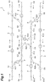
- Fig. 1 is a plan view of a track network for a traveling vehicle system according to one embodiment of the present invention.
- this traveling vehicle system 1 includes a track network 2 including straight tracks R1 to R16 and curved tracks R21 to R26 and a plurality of traveling vehicles 3 that travel in the arrow directions along the track network 2.
- a track network 2 including straight tracks R1 to R16 and curved tracks R21 to R26 and a plurality of traveling vehicles 3 that travel in the arrow directions along the track network 2.
- the traveling vehicles 3 detect their own positions in the track network 2 by reading positional information from the points P.
- Such a traveling vehicle system 1 is used for conveying workpieces such as semiconductor wafers and glass substrates from a conveyance source to a conveyance destination in a clean room of a factory for manufacturing semiconductor devices or liquid crystal displays, for example.
- the traveling vehicles 3 are overhead-traveling automated guided vehicles, and create traveling routes from conveyance sources to conveyance destinations by themselves and convey the workpieces from the conveyance sources to the conveyance destinations while detecting their own positions in the track network 2. Examples of the conveyance sources and the conveyance destinations include stations for performing various processes on the workpieces.
- the traveling vehicles 3 may be other types of automated guided vehicles such as automated guided vehicles traveling on rails.
- the track R2 and the track R21 diverge from the track R1 at a diverging section S1.
- the track R6 and the track R23 diverge from the track R5 at a diverging section S2.
- the track R8 and the track R22 diverge from the track R7 at a diverging section S3.
- the track R11 and the track R24 diverge from the track RIO at a diverging section S4.
- the track R13 and the track R26 diverge from the track R12 at a diverging section S5.
- the track R15 and the track R25 diverge from the track R14 at a diverging section S6.
- the track R2 and the track R22 merge into the track R3 at a merging section C1.
- the track R4 and the track R21 merge into the track R5 at a merging section C2.
- the track R6 and the track R24 merge into the track R7 at a merging section C3.
- the track R9 and the track R25 merge into the track R10 at a merging section C4.
- the track R11 and the track R23 merge into the track R12 at a merging section C5.
- the track R15 and the track R26 merge into the track R16 at a merging section C6.
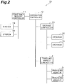
- Fig. 2 is a block diagram illustrating a configuration of a control system of the traveling vehicle system according to the embodiment of the present invention.
- this control system 10 of the traveling vehicle system 1 includes, in addition to a traveling vehicle controller 4 for controlling travel of the traveling vehicles 3, a conveyance request controller 11, a distribution controller 12, and a storage controller 13.
- the distribution controller 12 is a higher-order controller of the traveling vehicle controller 4 and the storage controller 13, and can communicate with each of the controllers 4 and 13.
- the conveyance request controller 11 can communicate with each of a plurality of stations 14 for performing various processes on workpieces.
- the storage controller 13 can communicate with each of a plurality of storages 15 for temporarily storing therein the workpieces.
- the traveling vehicle controller 4 can communicate with each of the traveling vehicles 3.
- the conveyance request controller 11 Having received a conveyance request (carry-in request and carry-out request) of workpieces from a station 14, the conveyance request controller 11 transmits the conveyance request to the distribution controller 12.
- the distribution controller 12 that has received the conveyance request transmits a storage-and-retrieval request of the workpieces to the storage controller 13 if necessary.
- the storage controller 13 that has received the storage-and-retrieval request transmits a storage-and-retrieval command to a storage 15.
- the storage 15 that has received the storage-and-retrieval command performs storage and retrieval of the workpieces on a traveling vehicle 3 at a predetermined timing.
- the distribution controller 12 that has received the conveyance request from the conveyance request controller 11 transmits the conveyance request to the traveling vehicle controller 4.
- the traveling vehicle controller 4 that has received the conveyance request transmits a conveyance command to the traveling vehicle 3.
- the traveling vehicle 3 that has received the conveyance command creates a traveling route from a station 14 being a conveyance source to another station 14 being a conveyance destination by itself, and conveys the workpieces from the station 14 being the conveyance source to the station 14 being the conveyance destination while detecting its own position in the track network 2.
- the traveling vehicle 3 reads positional information from the points P provided to the track network 2, thereby detecting its own position in the track network 2 to transmit the positional information of its own to the traveling vehicle controller 4 as needed.
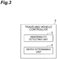
- Fig. 3 is a block diagram illustrating a configuration of the traveling vehicle controller depicted in Fig. 2 .
- the traveling vehicle controller 4 is an electronic control unit including a CPU, a ROM, and a RAM, for example, and includes at least an abnormality detecting unit (abnormality detecting means) 5 and an entry determining unit (entry determining means) 6.
- the traveling vehicle controller 4 loads a program stored in the ROM on the RAM and causes the CPU to execute the program, thereby constituting the abnormality detecting unit 5 and the entry determining unit 6 as software.
- the respective processing units of the traveling vehicle controller 4 may be constituted by hardware.
- the abnormality detecting unit 5 detects abnormality in the tracks R2, R6, R8, R11, R13, R15, and R21 to R26 that diverge from the respective diverging sections S1 to S6.
- the entry determining unit 6 determines whether the traveling vehicles 3 that are about to pass through the respective diverging sections S1 to S6 are allowed to enter the tracks R2, R6, R8, R11, R13, R15, and R21 to R26 on the basis of situations of abnormality detected by the abnormality detecting unit 5.
- the abnormality detecting unit 5 and the entry determining unit 6 will be described in further detail in [Processing Procedure in Traveling Vehicle Controller] below.
- the traveling vehicle 3A that has created a traveling route using one of the tracks R6 and R23, when approaching the diverging section S2 in the track R5, transmits a setting request for entry permission to the traveling vehicle controller 4 (step S51).
- This setting request for entry permission is designed to request the traveling vehicle controller 4 to set entry permission to pass through the diverging section S2 and enter one of the tracks R6 and R23.
- the traveling vehicle 3A passes through the diverging section S2 and enters the track R6 or the track R23 for which the entry permission has been set (step S53). Subsequently, the traveling vehicle 3A that has passed through the diverging section S2 transmits a request to cancel the entry permission to the traveling vehicle controller 4 (step S54).
- step S52 If the entry permission has not been set by the traveling vehicle controller 4 (step S52), the traveling vehicle 3A stops just before the section S2.
- a predetermined period e.g., a predetermined period of time since the setting request for entry permission was transmitted
- step S55 the traveling vehicle 3A performs a process of step S52.
- the traveling vehicle 3A re-creates a traveling route using the other one of the tracks R6 and R23 and transmits another setting request for entry permission to the traveling vehicle controller 4 (step S51), and performs processes of step S52 and the following steps.
- This other setting request for entry permission is designed to request the traveling controller 4 to set entry permission to pass through the diverging section S2 and enter the other one of the tracks R6 and R23.
- the traveling vehicle 3A requests the traveling vehicle controller 4 to set entry permission to pass through the diverging section S2 and enter the other one of the tracks R6 and R23.
- a processing procedure in the traveling vehicle controller 4 will be described with reference to the flowchart in Fig. 6 . It is assumed herein that the abnormality detecting unit 5 of the traveling vehicle controller 4 monitors the presence or absence of abnormality in the respective tracks R6 and R23.
- the entry determining unit 6 of the traveling vehicle controller 4 determines whether one of the tracks R6 and R23 that the traveling vehicle 3A (another one of the traveling vehicles 3 that has immediately thereafter passed through the diverging section S2) is about to enter is the same as the track R6 or the track R23 that a traveling vehicle 3B (one of the traveling vehicles 3 that has just passed through the diverging section S2) has entered (step S62). This determination process is performed based on the setting request for entry permission that has finally been received from the traveling vehicle 3B and the setting request for entry permission that has been received from the traveling vehicle 3A.
- the entry determining unit 6 determines whether the entry permission to the one of the tracks R6 and R23 has been canceled (step S63). In accordance with the determination, if the entry permission has not been canceled, the process returns to step S62, and if the entry permission has been canceled, the entry determining unit 6 sets the entry permission to the one of the tracks R6 and R23 (step S64).
- the entry determining unit 6 performs determination (herein, the determination process at step S63) of whether the traveling vehicle 3A is allowed to enter the one of the tracks R6 and R23 regardless of situations of abnormality detected by the abnormality detecting unit 5.
- the entry determining unit 6 determines whether abnormality in the one of the tracks R6 and R23 has been detected by the abnormality detecting unit 5 (step S65). In accordance with the determination, if abnormality has not been detected, the entry determining unit 6 sets the entry permission to the one of the tracks R6 and R23 (step S64) without determining whether the entry permission has been canceled.
- the entry determining unit 6 skips determination (herein, the determination process at step S63) of whether the traveling vehicle 3A is allowed to enter the one of the tracks R6 and R23.
- the entry determining unit 6 determines whether the entry permission to the one of the tracks R6 and R23 has been canceled (step S63). In accordance with the determination, if the entry permission has not been canceled, the process returns to step S62, and if the entry permission has been canceled, the entry determining unit 6 sets the entry permission to the other one of the tracks R6 and R23 (step S64).
- the entry determining unit 6 performs determination (herein, the determination process at step S63) of whether the traveling vehicle 3A is allowed to enter the other one of the tracks R6 and R23.
- the traveling vehicle controller 4 that has set the entry permission to the one of the tracks R6 and R23, when a request to cancel the entry permission is received from the traveling vehicle 3A that has passed through the diverging section S2 (step S66), cancels the entry permission (step S67).
- the abnormality detecting unit 5 stores therein in advance combinations of the diverging sections S1 to S6 and the merging sections C1 to C6, where the diverging sections S1 to S6 are subjects for which determination of whether entry thereto is allowed is made, and the merging sections C1 to C6 are subjects for which abnormality is detected.
- the diverging section S1 is associated with the merging sections C1 and C2 that are the nearest merging sections on the respective downstream sides thereof, and the abnormality detecting unit 5 stores a combination of the diverging section S1 and the merging sections C1 and C2 thus associated.
- the abnormality detecting unit 5 stores therein a combination of the diverging section S2 and the merging sections C3 and C5, a combination of the diverging section S3 and the merging section C1, a combination of the diverging section S4 and the merging sections C3 and C5, a combination of the diverging section S5 and the merging section C6, and a combination of the diverging section S6 and the merging sections C4 and C6.
- the abnormality detecting unit 5 performs the process for detecting abnormality as follows. For example, as depicted in Fig. 4 , in a situation that entry permission for a traveling vehicle 3C traveling in the track R6 to enter the merging section C3 has been set, if the traveling vehicle 3C has stopped due to occurrence of abnormality on the traveling vehicle 3C, the abnormality detecting unit 5 detects that the abnormality has occurred in the track R6 when the traveling vehicle 3C does not pass through the merging section C3 during the predetermined period.
- the abnormality detecting unit 5 detects that the abnormality has occurred in the track R6 when the traveling vehicle 3B that entered the track R6 and has stopped in the track R6 for the predetermined period. In other words, when the traveling vehicle 3B that had entered the track R6 stopped to keep an inter-vehicle distance from the traveling vehicle 3C and the predetermined period has elapsed in this state, the abnormality detecting unit 5 detects that the abnormality has occurred in the track R6 by communicating with the traveling vehicle 3B.
- Information on detecting the abnormality in the track R6 described above is used when determination is made of whether the traveling vehicle 3A that is about to pass through the diverging section S2 stored in association with the merging section C3 is allowed to enter the one of the tracks R6 and R23 (the determination process at step S65 performed by the entry determining unit 6 described above).
- traveling vehicle system 1 configured as above, it is possible to prevent areas of traffic congestion of the traveling vehicles 3 from widening even if any kind of abnormality has occurred downstream of the diverging sections S1 to S6, while improving the traveling efficiency of the traveling vehicles 3.
- the traveling vehicle system 1 in the case that the traveling vehicle 3B that has just entered the diverging section S2 enters the track R6 and the traveling vehicle 3A that has immediately thereafter passed through the diverging section S2 is about to consecutively enter the track R6, when abnormality in the track R6 has not been detected, determination is skipped of whether the traveling vehicle 3A that is about to consecutively enter the track R6 is allowed to enter the track R6.
- the traveling vehicle system 1 in the case that the traveling vehicle 3B that has just passed through the diverging section S2 enters the track R6 and the traveling vehicle 3A that has immediately thereafter passed through the diverging section S2 is about to consecutively enter the track R6, when abnormality in the track R6 has been detected, determination is made of whether the traveling vehicle 3A that is about to consecutively enter the track R6 is allowed to enter the track R6.
- the abnormality detecting unit 5 of the traveling vehicle controller 4 detects abnormality in the track R6 when the traveling vehicle 3C that has been determined to be allowed to enter the merging section C3 on the downstream side of the diverging section S2 does not pass through the merging section C3 during the predetermined period. Similarly, the abnormality detecting unit 5 detects the abnormality in the track R23 when the traveling vehicle 3 that has been determined to be allowed to enter the merging section C5 on the downstream side of the diverging section S2 does not pass through the merging section C5 during the predetermined period.
- These operations apply to such cases of the diverging sections S1, and S3 to S6. This eliminates the necessity of newly providing a sensor, for example, for detecting abnormality in the tracks R2, etc. on the downstream side of the diverging sections S1 to S6, thereby making it possible to detect abnormality in the tracks R2, etc. with such simple configurations.
- the abnormality detecting unit 5 stores therein in advance the combinations of the diverging sections S1 to S6 and the merging sections C1 to C6, where the diverging sections S1 to S6 are subjects for which determination of whether entry thereto is allowed is made, and the merging sections C1 to C6 are subjects for which abnormality is detected. This requires only processing for detecting abnormality in the tracks R2, etc. using as the subjects the merging sections C1 to C6 that are associated with the diverging sections S1 to S6, making it possible to detect abnormality in the tracks R2, etc. while preventing an increase in the processing load.
- the abnormality detecting unit 5 detects abnormality when the traveling vehicle 3B that has entered the tracks R2, etc. on the downstream side of the diverging sections S1 to S6 makes an inter-vehicle stop for the predetermined period. This eliminates the necessity of newly providing a sensor, for example, for detecting abnormality in the tracks R2, etc. on the downstream side of the diverging sections S1 to S6, thereby making it possible to detect abnormality in the tracks R2, etc. with such simple configurations.
- the traveling vehicle 3A has made a setting request for entry permission to pass through the diverging section S2 and enter one of the tracks R6 and R23
- the traveling vehicle 3A makes a setting request for entry permission to pass through the diverging section S2 and enter the other one of the tracks R6 and R23. Accordingly, the traveling vehicle 3A that has made the setting request for entry permission to pass through the diverging section S2 and enter the one of the tracks R6 and R23 can be avoided from continuously stopping just before the diverging section S2 when abnormality has occurred in the one of the tracks R6 and R23.
- the abnormality detecting unit 5 of the traveling vehicle controller 4 is not limited to a unit for detecting abnormality in the tracks R2, etc. (e.g., the track R2 or the track R21 for the diverging section S1), and may be a unit for detecting abnormality in tracks (e.g., the tracks R2 and R3 or the tracks R21 and R5 for the diverging section S1) on the downstream side of the diverging sections S1 to S6 including at least the tracks S2, etc.
- traveling vehicles 3 that have been determined to be allowed to enter predetermined sections (in addition to the merging sections C1 to C6, diverging sections at which the tracks R2, etc.
- the abnormality detecting unit 5 may detect abnormality in the tracks on the downstream side.
- the present invention it is possible to provide a traveling vehicle system that can prevent areas of traffic congestion of traveling vehicles from widening even if any kind of abnormality has occurred downstream of a diverging section, while improving the traveling efficiency of the traveling vehicles.
Landscapes
- Engineering & Computer Science (AREA)
- Radar, Positioning & Navigation (AREA)
- Remote Sensing (AREA)
- Aviation & Aerospace Engineering (AREA)
- Physics & Mathematics (AREA)
- General Physics & Mathematics (AREA)
- Automation & Control Theory (AREA)
- Mechanical Engineering (AREA)
- Control Of Position, Course, Altitude, Or Attitude Of Moving Bodies (AREA)
- Electric Propulsion And Braking For Vehicles (AREA)
Claims (12)
- Un système de véhicules de déplacement (1) comprenant :un réseau de voies (2) comprenant une première voie (R1) et une deuxième voie (R2) et une troisième voie (R21) qui divergent de la première voie (R1) dans une section divergente (S1) ;une pluralité de véhicules de déplacement (3) qui circulent dans le réseau de voies (2) ; etune commande (4) qui commande le déplacement des véhicules de déplacement (3), dans lequelchacun des véhicules de déplacement (3) est adapté pour faire une demande d'établissement d'autorisation d'accès pour passer par la section divergente et entrer dans la deuxième voie (R2) ou la troisième voie (R21) et, lorsque l'autorisation d'accès est réglée par la commande (4), passe par la section divergente (S1) et entre dans la deuxième voie (R2) ou la troisième voie (R21)
etla commande (4) est caractérisé par :des moyens de détection d'anomalie (5) pour détecter une anomalie dans une voie sur le côté aval de la section divergente (S1), comprenant au moins la deuxième voie (R2); etdes moyens de détermination d'accès (6) adaptés pour, dans le cas oùa) chacun des véhicules de déplacement (3) qui est passé par la section divergente (S1) immédiatement avant, entre dans une voie autre que la deuxième voie (R2), et où chacun des véhicules de déplacement (3) qui passe par la section divergente (S1) immédiatement après, est sur le point d'entrer dans la deuxième voie (R2) (« NON » à l'étape S62),
il est déterminé si chacun des véhicules de déplacement (3) qui passent par la section divergente (S1) immédiatement après, a une autorisation d'entrer dans la deuxième voie (R2) (S63 de la figure 6),
l'autorisation d'accès à la deuxième voie (R2) étant établie s'il est détermine que l'accès est autorisé (S64 de la figure 6), et
l'autorisation d'accès à la deuxième voie (R2) n'étant pas établie s'il est déterminé que l'accès n'est pas autorisée (« NON » à l'étape S63) ;b) lorsque l'anomalie n'a pas été détectée par le moyen de détection d'anomalie (5) (« NON » à l'étape S65) dans le cas où chacun des véhicules de déplacement (3) qui sont passés par la section divergente (S1) immédiatement avant, entre dans la deuxième voie (R2), et chacun des véhicules de déplacement (3) qui passent par la section divergente (S1) immédiatement après, est sur le point d'entrer consécutivement dans la deuxième voie (R2) (« OUI» à l'étape S62),
la détermination si chacun des véhicules de déplacement (3) qui passent par la section divergente (S1) immédiatement après, a l'autorisation d'accès à la deuxième voie (R2) est omise, et l'autorisation d'accès dans la deuxième voie (R2) est établie (S64 de la figure 6) ;c) lorsque l'anomalie a été détectée par le moyen de détection d'anomalie (5) (« OUI» à l'étape S65) dans le cas où chacun des véhicules de déplacement (3) qui sont passés par la section divergente (S1) immédiatement avant, entre dans la deuxième voie (R2), et chacun des véhicules de déplacement (3) qui passent par la section divergente (S1) immédiatement après, est consécutivement sur le point d'entrer dans la deuxième voie (R2) (« OUI» à l'étape S62),
il est déterminé si chacun des véhicules de déplacement (3) qui passent par la section divergente (S1) immédiatement après, a une autorisation d'accès à la deuxième voie (R2) (S63 de la figure 6),
l'autorisation d'accès à la deuxième voie (R2) étant établie s'il est déterminé que l'accès est autorisé (S64 de la figure 6), et
l'autorisation d'accès à la deuxième voie (R2) n'étant pas établie s'il est déterminé que l'accès n'est pas autorisé (« NON » à l'étape S63). - Le système de véhicules de déplacement (1) selon la revendication 1, dans lequel le moyen de détection d'anomalie (5) est adapté pour détecter l'anomalie lorsqu'un des véhicules de déplacement (3) qui a été déterminé pour être autorisé à entrer dans une section prédéterminée de la voie sur le côté aval ne passe pas par la section prédéterminée pendant une période prédéterminée.
- Le système de véhicules de déplacement (1) selon la revendication 2, dans lequel la section prédéterminée est une section de fusion (C3) sur le côté aval, à laquelle la deuxième voie (R2) fusionne avec une autre voie.
- Le système de véhicules de déplacement (1) selon la revendication 2 ou 3, dans lequel le moyen de détection d'anomalie (5) est adapté pour y stocker à l'avance une combinaison de la section divergente (S1) et de la section prédéterminée, où la section divergente (S1) est un sujet pour lequel il est déterminé si l'autre des véhicules (3) qui est passé immédiatement après par la section divergente (S1) est autorisé à entrer dans la deuxième voie (R2), et la section prédéterminée est un sujet pour lequel on détecte l'anomalie.
- Le système de véhicules de déplacement (1) selon l'une quelconque des revendications 1 à 4, dans lequel le moyen de détection d'anomalie (5) est adapté pour détecter l'anomalie lorsque l'un des véhicules de déplacement (3) qui est entré dans la deuxième voie (R2) effectue un arrêt entre véhicules pendant une période prédéterminée dans la voie (R2) sur le côté aval.
- Le système de véhicules de déplacement (1) selon l'une quelconque des revendications 1 à 5, dans lequel,
après avoir fait la demande de réglage d'autorisation d'accès pour passer par la section divergente (S1) et entrer dans la deuxième voie (R2), lorsque l'autorisation d'accès n'est pas réglée par la commande (4) pendant une période prédéterminée, le véhicule de déplacement (3) est adapté pour demander le réglage d'autorisation d'accès pour passer par la section divergente (S1) et pour entrer dans la troisième voie (R21). - Un procédé de fonctionnement d'un système de véhicules de déplacement (1) comprenant :un réseau de voies (2) comprenant une première voie (R1) et une deuxième voie (R2) et une troisième voie (R21) qui divergent de la première voie (R1) dans une section divergente (S1) ;une pluralité de véhicules de déplacement (3) qui circulent dans le réseau de voies (2) ; etune commande (4) qui commande le déplacement des véhicules de déplacement (3), dans laquellechacun des véhicules de déplacement (3) fait une demande d'établissement pour une autorisation d'accès pour passer par la section divergente et entrer dans la deuxième voie (R2) ou la troisième voie (R21) et, lorsque l'autorisation d'accès est établie par la commande (4), passe par la section divergente (S1) et entre dans la deuxième voie (R2) ou la troisième voie (R21), etla commande (4) est caractérisée par :des moyens de détection d'anomalie (5) pour détecter une anomalie dans une voie sur le côté aval de la section divergente (S1), comprenant au moins la deuxième voie (R2) ; etdes moyens de détermination d'accès (6) adaptés pour, dans un cas suivanta) si chacun des véhicules de déplacement (3) qui est passé par la section divergente (S1) immédiatement avant, entre dans une voie autre que la deuxième voie (R2), et si chacun des véhicules de déplacement (3) qui passent par la section divergente (S1) immédiatement après, est sur le point d'entrer dans la deuxième voie (R2) (« NON » à l'étape S62),
il est déterminé si chacun des véhicules de déplacement (3) qui passent par la section divergente (S1) immédiatement après, a l'autorisation d'entrer dans la deuxième voie (R2) (S63 de la figure 6),
le droit d'accès à la deuxième voie (R2) étant établi s'il est déterminé que l'accès est autorisé (S64 de la figure 6), et
le droit d'accès à la deuxième voie (R2) n'étant pas établi s'il est déterminé que l'accès est interdit (« NON » à l'étape S63);b) lorsque l'anomalie n'a pas été détectée par le moyen de détection d'anomalie (5) (« NON » à l'étape S65) dans le cas où chacun des véhicules de déplacement (3) qui sont passés par la section divergente (S1) immédiatement avant, entre dans la deuxième voie (R2), et chacun des véhicules de déplacement (3) qui passent par la section divergente (S1) immédiatement après, est sur le point d'entrer consécutivement dans la deuxième voie (R2) (« OUI» à l'étape S62),
la détermination du fait que chacun des véhicules de déplacement (3) qui passent par la section divergente (S1) immédiatement après, a l'autorisation d'entrer dans la deuxième voie (R2) est omise et l'autorisation d'entrer dans la deuxième voie (R2) est établie (S64 de la figure 6) ;c) lorsque l'anomalie a été détectée par le moyen de détection d'anomalie (5) (« OUI » à l'étape S65) dans le cas où chacun des véhicules de déplacement (3) qui sont passés par la section divergente (S1) immédiatement avant, entre dans la deuxième voie (R2), et chacun des véhicules de déplacement (3) qui passent par la section divergente (S1) immédiatement après, est sur le point d'entrer consécutivement dans la deuxième voie (R2) (« OUI» à l'étape S62),
il est déterminé si chacun des véhicules de déplacement (3) qui passent par la section divergente (S1) immédiatement après, a l'autorisation d'entrer dans la deuxième voie (R2) (S63 de la figure 6),
l'autorisation d'accès à la deuxième voie (R2) étant établie s'il est déterminé que l'accès est autorisé (S64 de la figure 6), et
l'autorisation d'accès à la deuxième voie (R2) n'étant pas établie s'il est déterminé que l'accès n'est pas autorisé (« NON » à l'étape S63). - Le procédé selon la revendication 7, dans lequel le moyen de détection d'anomalie (5) détecte l'anomalie lorsqu'un des véhicules de déplacement (3) qui a été déterminé pour être autorisé à entrer dans une section prédéterminée de la voie sur le côté aval ne passe pas par la section prédéterminée pendant une période prédéterminée.
- Le procédé selon la revendication 8, dans lequel la section prédéterminée est une section de fusion (C3) sur le côté aval, à laquelle la deuxième voie (R2) fusionne avec une autre voie.
- Le procédé selon la revendication 8 ou 9, dans lequel le moyen de détection d'anomalie (5) stocke à l'avance une combinaison de la section divergente (S1) et de la section prédéterminée, la section divergente (S1) étant un sujet pour lequel il est déterminé si l'autre des véhicules (3) qui est passé immédiatement après par la section divergente (S1) est autorisé à pénétrer dans la deuxième voie (R2), et la section prédéterminée est un sujet pour lequel l'anomalie est détectée.
- Le procédé selon l'une quelconque des revendications 7 à 10 ; dans lequel le moyen de détection d'anomalie (5) détecte l'anomalie lorsque l'un des véhicules de déplacement (3) qui est entré dans la deuxième voie (R2) effectue un arrêt entre véhicules pendant une période prédéterminée dans la voie (R2) sur le côté aval.
- Le procédé selon l'une quelconque des revendications 7 à 11, dans lequel,
après avoir fait la demande d'établissement d'autorisation d'accès pour passer par la section divergente (S1) et entrer dans la deuxième voie (R2), lorsque l'autorisation d'accès n'est pas établie par la commande (4) pendant une période prédéterminée, le véhicule de déplacement (3) demande l'établissement de l'autorisation d'accès pour passer par la section divergente (S1) et entrer dans la troisième voie de déplacement (R21).
Applications Claiming Priority (2)
| Application Number | Priority Date | Filing Date | Title |
|---|---|---|---|
| JP2012006876 | 2012-01-17 | ||
| PCT/JP2012/081524 WO2013108501A1 (fr) | 2012-01-17 | 2012-12-05 | Système de véhicule de déplacement |
Publications (3)
| Publication Number | Publication Date |
|---|---|
| EP2806323A1 EP2806323A1 (fr) | 2014-11-26 |
| EP2806323A4 EP2806323A4 (fr) | 2015-08-05 |
| EP2806323B1 true EP2806323B1 (fr) | 2019-08-21 |
Family
ID=48798938
Family Applications (1)
| Application Number | Title | Priority Date | Filing Date |
|---|---|---|---|
| EP12866311.9A Not-in-force EP2806323B1 (fr) | 2012-01-17 | 2012-12-05 | Système de véhicule de déplacement |
Country Status (8)
| Country | Link |
|---|---|
| US (1) | US9285806B2 (fr) |
| EP (1) | EP2806323B1 (fr) |
| JP (1) | JP5748006B2 (fr) |
| KR (1) | KR101603086B1 (fr) |
| CN (1) | CN104067191B (fr) |
| SG (1) | SG11201404187WA (fr) |
| TW (1) | TWI584092B (fr) |
| WO (1) | WO2013108501A1 (fr) |
Families Citing this family (30)
| Publication number | Priority date | Publication date | Assignee | Title |
|---|---|---|---|---|
| WO2014011887A1 (fr) * | 2012-07-11 | 2014-01-16 | Carnegie Mellon University | Système de verrouillage de voie ferrée à commande répartie |
| US9043056B2 (en) * | 2013-07-08 | 2015-05-26 | Disney Enterprises, Inc. | Method and system for using dynamic boundaries to manage the progression of ride vehicles that have rider control inputs |
| JP6270518B2 (ja) * | 2014-02-05 | 2018-01-31 | 日立建機株式会社 | 作業車両の管制システム |
| US9389614B2 (en) * | 2014-04-08 | 2016-07-12 | Unitronics Automated Solutions Ltd | System and method for tracking guiding lines by an autonomous vehicle |
| WO2015186440A1 (fr) * | 2014-06-02 | 2015-12-10 | 村田機械株式会社 | Système de véhicule roulant et procédé de commande de véhicule roulant |
| JP6331896B2 (ja) * | 2014-09-02 | 2018-05-30 | 村田機械株式会社 | 走行車システム |
| CN105158654B (zh) * | 2015-08-24 | 2017-09-26 | 大连世有电力科技有限公司 | 用于变压器局部放电诊断的智能机器人 |
| CN108352349B (zh) * | 2015-12-09 | 2022-07-22 | 村田机械株式会社 | 输送系统和输送方法 |
| JP6613941B2 (ja) * | 2016-02-10 | 2019-12-04 | 株式会社ダイフク | 物品搬送設備 |
| JP6520797B2 (ja) * | 2016-04-11 | 2019-05-29 | 株式会社ダイフク | 物品搬送設備 |
| US9921582B2 (en) * | 2016-04-20 | 2018-03-20 | GM Global Technology Operations LLC | Reconfigurable automated guided vehicle system |
| JP6652084B2 (ja) * | 2017-02-09 | 2020-02-19 | 株式会社ダイフク | 物品搬送設備 |
| JP6601805B2 (ja) * | 2017-04-28 | 2019-11-06 | 株式会社Subaru | 車両 |
| JP6963908B2 (ja) * | 2017-05-09 | 2021-11-10 | 株式会社ダイフク | 物品搬送車 |
| JP6825532B2 (ja) * | 2017-10-12 | 2021-02-03 | 株式会社ダイフク | 搬送システム |
| SG11202008642UA (en) * | 2018-03-15 | 2020-10-29 | Murata Machinery Ltd | Traveling vehicle controller and traveling vehicle system |
| US10401870B1 (en) * | 2018-11-15 | 2019-09-03 | Grey Orange Pte. Ltd. | System and method for handling items using movable-bots |
| JP7081567B2 (ja) * | 2019-05-20 | 2022-06-07 | 株式会社ダイフク | 物品搬送装置 |
| JP2022125369A (ja) * | 2019-07-04 | 2022-08-29 | 村田機械株式会社 | 走行システム |
| US11635770B2 (en) * | 2019-07-12 | 2023-04-25 | Murata Machinery, Ltd. | Traveling vehicle system and traveling vehicle control method |
| CN110938807B (zh) * | 2019-11-26 | 2022-10-21 | 北京北方华创微电子装备有限公司 | Pvd溅射设备的晶圆按指定路径回盘的控制方法及系统 |
| JP7334633B2 (ja) * | 2020-01-31 | 2023-08-29 | 株式会社ダイフク | 物品搬送装置 |
| JP7327666B2 (ja) * | 2020-05-27 | 2023-08-16 | 村田機械株式会社 | 走行車システム、及び走行車の制御方法 |
| WO2021241046A1 (fr) * | 2020-05-27 | 2021-12-02 | 村田機械株式会社 | Système de chariots et procédé destiné à commander un chariot |
| CN112320257A (zh) * | 2020-10-28 | 2021-02-05 | 浙江瑞晟智能科技股份有限公司 | 载具变轨检测方法及系统 |
| JP7331882B2 (ja) * | 2021-04-23 | 2023-08-23 | 株式会社ダイフク | 物品搬送設備、経路設定方法、及び経路設定プログラム |
| JP7375791B2 (ja) * | 2021-05-19 | 2023-11-08 | 村田機械株式会社 | 走行車システム |
| KR102889556B1 (ko) * | 2022-06-17 | 2025-11-25 | 세메스 주식회사 | 주행 비히클을 이용한 레일 환경 모니터링 장치 및 방법과 이를 포함하는 물류 이송 장비 |
| CN116453993B (zh) * | 2023-06-15 | 2023-09-08 | 上海果纳半导体技术有限公司 | 天车搬运系统、搬运方法和可存储介质 |
| WO2025158715A1 (fr) * | 2024-01-22 | 2025-07-31 | 村田機械株式会社 | Système pour véhicule en déplacement |
Family Cites Families (12)
| Publication number | Priority date | Publication date | Assignee | Title |
|---|---|---|---|---|
| JP4503333B2 (ja) | 2004-03-30 | 2010-07-14 | 村田機械株式会社 | 搬送台車システム |
| JP2006313461A (ja) | 2005-05-09 | 2006-11-16 | Murata Mach Ltd | 搬送台車システム |
| JP2007257154A (ja) * | 2006-03-22 | 2007-10-04 | Asyst Shinko Inc | 搬送車管理装置、搬送車管理システム、搬送車管理方法及び搬送車管理プログラム |
| JP4306723B2 (ja) * | 2006-12-15 | 2009-08-05 | 村田機械株式会社 | 搬送台車システム |
| JP4240333B2 (ja) * | 2007-05-01 | 2009-03-18 | 村田機械株式会社 | 走行車システム |
| CN100494900C (zh) * | 2007-07-03 | 2009-06-03 | 北京控制工程研究所 | 适用于自主移动车辆的环境感知的单目视觉导航方法 |
| WO2009142051A1 (fr) * | 2008-05-22 | 2009-11-26 | 村田機械株式会社 | Système de véhicule en déplacement et procédé de commande du déplacement d'un système de véhicule en déplacement |
| JP5019540B2 (ja) | 2008-07-01 | 2012-09-05 | 村田機械株式会社 | 搬送システム及び搬送車 |
| KR101246280B1 (ko) * | 2008-09-26 | 2013-03-22 | 무라다기카이가부시끼가이샤 | 반송차 시스템 |
| JP4811454B2 (ja) * | 2008-12-02 | 2011-11-09 | 村田機械株式会社 | 搬送台車システム及び搬送台車への走行経路の指示方法 |
| CN101963812B (zh) * | 2009-07-24 | 2013-02-20 | 株式会社Ihi | 无人输送装置和其输送路径决定方法 |
| JP5104909B2 (ja) * | 2010-06-23 | 2012-12-19 | 村田機械株式会社 | 搬送車システム |
-
2012
- 2012-12-05 EP EP12866311.9A patent/EP2806323B1/fr not_active Not-in-force
- 2012-12-05 WO PCT/JP2012/081524 patent/WO2013108501A1/fr not_active Ceased
- 2012-12-05 JP JP2013554198A patent/JP5748006B2/ja active Active
- 2012-12-05 KR KR1020147013388A patent/KR101603086B1/ko not_active Expired - Fee Related
- 2012-12-05 US US14/372,522 patent/US9285806B2/en active Active
- 2012-12-05 SG SG11201404187WA patent/SG11201404187WA/en unknown
- 2012-12-05 CN CN201280067379.7A patent/CN104067191B/zh active Active
-
2013
- 2013-01-09 TW TW102100703A patent/TWI584092B/zh active
Non-Patent Citations (1)
| Title |
|---|
| None * |
Also Published As
| Publication number | Publication date |
|---|---|
| WO2013108501A1 (fr) | 2013-07-25 |
| CN104067191A (zh) | 2014-09-24 |
| KR20140088157A (ko) | 2014-07-09 |
| JP5748006B2 (ja) | 2015-07-15 |
| TW201337488A (zh) | 2013-09-16 |
| KR101603086B1 (ko) | 2016-03-14 |
| CN104067191B (zh) | 2016-04-27 |
| US20140358338A1 (en) | 2014-12-04 |
| SG11201404187WA (en) | 2014-10-30 |
| EP2806323A4 (fr) | 2015-08-05 |
| JPWO2013108501A1 (ja) | 2015-05-11 |
| US9285806B2 (en) | 2016-03-15 |
| EP2806323A1 (fr) | 2014-11-26 |
| TWI584092B (zh) | 2017-05-21 |
Similar Documents
| Publication | Publication Date | Title |
|---|---|---|
| EP2806323B1 (fr) | Système de véhicule de déplacement | |
| US9280154B2 (en) | Vehicle system and vehicle control method | |
| US11226637B2 (en) | Traveling vehicle system, and control method for traveling vehicle system | |
| US10479613B2 (en) | Transport system and transport method | |
| WO2009142051A1 (fr) | Système de véhicule en déplacement et procédé de commande du déplacement d'un système de véhicule en déplacement | |
| EP4160348B1 (fr) | Système pour véhicule en mouvement et procédé de commande de véhicule en mouvement | |
| CN105383526A (zh) | 一种列车冲突检查及解决方法和列车自动监控系统 | |
| EP2957974B1 (fr) | Système de transport | |
| JP4099723B2 (ja) | 搬送台車システム | |
| US20240025659A1 (en) | Article Transport Facility | |
| KR20200053744A (ko) | 주행 시스템, 이에 포함되는 자동 주행 장치 및 교차점 충돌 방지 방법 | |
| EP2345944B1 (fr) | Système de véhicule | |
| KR20230091973A (ko) | 주행차 시스템 및 주행차의 제어 방법 | |
| JP4172466B2 (ja) | 搬送台車システム | |
| KR102534375B1 (ko) | 비히클의 경로 탐색 방법 | |
| CN117246699A (zh) | 物品搬送设备 | |
| JP2010079554A (ja) | 搬送車システム | |
| WO2023214492A1 (fr) | Système de véhicule en mouvement | |
| CN119637402A (zh) | 一种多车交管控制的硬件系统及使用方法 |
Legal Events
| Date | Code | Title | Description |
|---|---|---|---|
| PUAI | Public reference made under article 153(3) epc to a published international application that has entered the european phase |
Free format text: ORIGINAL CODE: 0009012 |
|
| 17P | Request for examination filed |
Effective date: 20140716 |
|
| AK | Designated contracting states |
Kind code of ref document: A1 Designated state(s): AL AT BE BG CH CY CZ DE DK EE ES FI FR GB GR HR HU IE IS IT LI LT LU LV MC MK MT NL NO PL PT RO RS SE SI SK SM TR |
|
| DAX | Request for extension of the european patent (deleted) | ||
| RA4 | Supplementary search report drawn up and despatched (corrected) |
Effective date: 20150706 |
|
| RIC1 | Information provided on ipc code assigned before grant |
Ipc: H01L 21/67 20060101ALI20150630BHEP Ipc: G05D 1/02 20060101AFI20150630BHEP Ipc: H01L 21/677 20060101ALI20150630BHEP |
|
| RIC1 | Information provided on ipc code assigned before grant |
Ipc: H01L 21/67 20060101ALI20190320BHEP Ipc: B61L 23/04 20060101ALI20190320BHEP Ipc: H01L 21/677 20060101ALI20190320BHEP Ipc: G05D 1/02 20060101AFI20190320BHEP |
|
| GRAP | Despatch of communication of intention to grant a patent |
Free format text: ORIGINAL CODE: EPIDOSNIGR1 |
|
| STAA | Information on the status of an ep patent application or granted ep patent |
Free format text: STATUS: GRANT OF PATENT IS INTENDED |
|
| INTG | Intention to grant announced |
Effective date: 20190426 |
|
| GRAS | Grant fee paid |
Free format text: ORIGINAL CODE: EPIDOSNIGR3 |
|
| GRAA | (expected) grant |
Free format text: ORIGINAL CODE: 0009210 |
|
| STAA | Information on the status of an ep patent application or granted ep patent |
Free format text: STATUS: THE PATENT HAS BEEN GRANTED |
|
| AK | Designated contracting states |
Kind code of ref document: B1 Designated state(s): AL AT BE BG CH CY CZ DE DK EE ES FI FR GB GR HR HU IE IS IT LI LT LU LV MC MK MT NL NO PL PT RO RS SE SI SK SM TR |
|
| REG | Reference to a national code |
Ref country code: GB Ref legal event code: FG4D |
|
| REG | Reference to a national code |
Ref country code: CH Ref legal event code: EP |
|
| REG | Reference to a national code |
Ref country code: DE Ref legal event code: R096 Ref document number: 602012063254 Country of ref document: DE |
|
| REG | Reference to a national code |
Ref country code: AT Ref legal event code: REF Ref document number: 1170469 Country of ref document: AT Kind code of ref document: T Effective date: 20190915 |
|
| REG | Reference to a national code |
Ref country code: IE Ref legal event code: FG4D |
|
| REG | Reference to a national code |
Ref country code: LT Ref legal event code: MG4D |
|
| REG | Reference to a national code |
Ref country code: NL Ref legal event code: MP Effective date: 20190821 |
|
| PG25 | Lapsed in a contracting state [announced via postgrant information from national office to epo] |
Ref country code: NO Free format text: LAPSE BECAUSE OF FAILURE TO SUBMIT A TRANSLATION OF THE DESCRIPTION OR TO PAY THE FEE WITHIN THE PRESCRIBED TIME-LIMIT Effective date: 20191121 Ref country code: PT Free format text: LAPSE BECAUSE OF FAILURE TO SUBMIT A TRANSLATION OF THE DESCRIPTION OR TO PAY THE FEE WITHIN THE PRESCRIBED TIME-LIMIT Effective date: 20191223 Ref country code: HR Free format text: LAPSE BECAUSE OF FAILURE TO SUBMIT A TRANSLATION OF THE DESCRIPTION OR TO PAY THE FEE WITHIN THE PRESCRIBED TIME-LIMIT Effective date: 20190821 Ref country code: SE Free format text: LAPSE BECAUSE OF FAILURE TO SUBMIT A TRANSLATION OF THE DESCRIPTION OR TO PAY THE FEE WITHIN THE PRESCRIBED TIME-LIMIT Effective date: 20190821 Ref country code: FI Free format text: LAPSE BECAUSE OF FAILURE TO SUBMIT A TRANSLATION OF THE DESCRIPTION OR TO PAY THE FEE WITHIN THE PRESCRIBED TIME-LIMIT Effective date: 20190821 Ref country code: LT Free format text: LAPSE BECAUSE OF FAILURE TO SUBMIT A TRANSLATION OF THE DESCRIPTION OR TO PAY THE FEE WITHIN THE PRESCRIBED TIME-LIMIT Effective date: 20190821 Ref country code: NL Free format text: LAPSE BECAUSE OF FAILURE TO SUBMIT A TRANSLATION OF THE DESCRIPTION OR TO PAY THE FEE WITHIN THE PRESCRIBED TIME-LIMIT Effective date: 20190821 Ref country code: BG Free format text: LAPSE BECAUSE OF FAILURE TO SUBMIT A TRANSLATION OF THE DESCRIPTION OR TO PAY THE FEE WITHIN THE PRESCRIBED TIME-LIMIT Effective date: 20191121 |
|
| PG25 | Lapsed in a contracting state [announced via postgrant information from national office to epo] |
Ref country code: GR Free format text: LAPSE BECAUSE OF FAILURE TO SUBMIT A TRANSLATION OF THE DESCRIPTION OR TO PAY THE FEE WITHIN THE PRESCRIBED TIME-LIMIT Effective date: 20191122 Ref country code: AL Free format text: LAPSE BECAUSE OF FAILURE TO SUBMIT A TRANSLATION OF THE DESCRIPTION OR TO PAY THE FEE WITHIN THE PRESCRIBED TIME-LIMIT Effective date: 20190821 Ref country code: ES Free format text: LAPSE BECAUSE OF FAILURE TO SUBMIT A TRANSLATION OF THE DESCRIPTION OR TO PAY THE FEE WITHIN THE PRESCRIBED TIME-LIMIT Effective date: 20190821 Ref country code: LV Free format text: LAPSE BECAUSE OF FAILURE TO SUBMIT A TRANSLATION OF THE DESCRIPTION OR TO PAY THE FEE WITHIN THE PRESCRIBED TIME-LIMIT Effective date: 20190821 Ref country code: RS Free format text: LAPSE BECAUSE OF FAILURE TO SUBMIT A TRANSLATION OF THE DESCRIPTION OR TO PAY THE FEE WITHIN THE PRESCRIBED TIME-LIMIT Effective date: 20190821 Ref country code: IS Free format text: LAPSE BECAUSE OF FAILURE TO SUBMIT A TRANSLATION OF THE DESCRIPTION OR TO PAY THE FEE WITHIN THE PRESCRIBED TIME-LIMIT Effective date: 20191221 |
|
| REG | Reference to a national code |
Ref country code: AT Ref legal event code: MK05 Ref document number: 1170469 Country of ref document: AT Kind code of ref document: T Effective date: 20190821 |
|
| PG25 | Lapsed in a contracting state [announced via postgrant information from national office to epo] |
Ref country code: TR Free format text: LAPSE BECAUSE OF FAILURE TO SUBMIT A TRANSLATION OF THE DESCRIPTION OR TO PAY THE FEE WITHIN THE PRESCRIBED TIME-LIMIT Effective date: 20190821 |
|
| PG25 | Lapsed in a contracting state [announced via postgrant information from national office to epo] |
Ref country code: PL Free format text: LAPSE BECAUSE OF FAILURE TO SUBMIT A TRANSLATION OF THE DESCRIPTION OR TO PAY THE FEE WITHIN THE PRESCRIBED TIME-LIMIT Effective date: 20190821 Ref country code: EE Free format text: LAPSE BECAUSE OF FAILURE TO SUBMIT A TRANSLATION OF THE DESCRIPTION OR TO PAY THE FEE WITHIN THE PRESCRIBED TIME-LIMIT Effective date: 20190821 Ref country code: RO Free format text: LAPSE BECAUSE OF FAILURE TO SUBMIT A TRANSLATION OF THE DESCRIPTION OR TO PAY THE FEE WITHIN THE PRESCRIBED TIME-LIMIT Effective date: 20190821 Ref country code: IT Free format text: LAPSE BECAUSE OF FAILURE TO SUBMIT A TRANSLATION OF THE DESCRIPTION OR TO PAY THE FEE WITHIN THE PRESCRIBED TIME-LIMIT Effective date: 20190821 Ref country code: AT Free format text: LAPSE BECAUSE OF FAILURE TO SUBMIT A TRANSLATION OF THE DESCRIPTION OR TO PAY THE FEE WITHIN THE PRESCRIBED TIME-LIMIT Effective date: 20190821 Ref country code: DK Free format text: LAPSE BECAUSE OF FAILURE TO SUBMIT A TRANSLATION OF THE DESCRIPTION OR TO PAY THE FEE WITHIN THE PRESCRIBED TIME-LIMIT Effective date: 20190821 |
|
| PG25 | Lapsed in a contracting state [announced via postgrant information from national office to epo] |
Ref country code: SM Free format text: LAPSE BECAUSE OF FAILURE TO SUBMIT A TRANSLATION OF THE DESCRIPTION OR TO PAY THE FEE WITHIN THE PRESCRIBED TIME-LIMIT Effective date: 20190821 Ref country code: SK Free format text: LAPSE BECAUSE OF FAILURE TO SUBMIT A TRANSLATION OF THE DESCRIPTION OR TO PAY THE FEE WITHIN THE PRESCRIBED TIME-LIMIT Effective date: 20190821 Ref country code: CZ Free format text: LAPSE BECAUSE OF FAILURE TO SUBMIT A TRANSLATION OF THE DESCRIPTION OR TO PAY THE FEE WITHIN THE PRESCRIBED TIME-LIMIT Effective date: 20190821 Ref country code: IS Free format text: LAPSE BECAUSE OF FAILURE TO SUBMIT A TRANSLATION OF THE DESCRIPTION OR TO PAY THE FEE WITHIN THE PRESCRIBED TIME-LIMIT Effective date: 20200224 |
|
| REG | Reference to a national code |
Ref country code: DE Ref legal event code: R097 Ref document number: 602012063254 Country of ref document: DE |
|
| PLBE | No opposition filed within time limit |
Free format text: ORIGINAL CODE: 0009261 |
|
| STAA | Information on the status of an ep patent application or granted ep patent |
Free format text: STATUS: NO OPPOSITION FILED WITHIN TIME LIMIT |
|
| PG2D | Information on lapse in contracting state deleted |
Ref country code: IS |
|
| REG | Reference to a national code |
Ref country code: CH Ref legal event code: PL |
|
| 26N | No opposition filed |
Effective date: 20200603 |
|
| REG | Reference to a national code |
Ref country code: BE Ref legal event code: MM Effective date: 20191231 |
|
| PG25 | Lapsed in a contracting state [announced via postgrant information from national office to epo] |
Ref country code: MC Free format text: LAPSE BECAUSE OF FAILURE TO SUBMIT A TRANSLATION OF THE DESCRIPTION OR TO PAY THE FEE WITHIN THE PRESCRIBED TIME-LIMIT Effective date: 20190821 Ref country code: SI Free format text: LAPSE BECAUSE OF FAILURE TO SUBMIT A TRANSLATION OF THE DESCRIPTION OR TO PAY THE FEE WITHIN THE PRESCRIBED TIME-LIMIT Effective date: 20190821 |
|
| GBPC | Gb: european patent ceased through non-payment of renewal fee |
Effective date: 20191205 |
|
| PG25 | Lapsed in a contracting state [announced via postgrant information from national office to epo] |
Ref country code: GB Free format text: LAPSE BECAUSE OF NON-PAYMENT OF DUE FEES Effective date: 20191205 Ref country code: LU Free format text: LAPSE BECAUSE OF NON-PAYMENT OF DUE FEES Effective date: 20191205 Ref country code: FR Free format text: LAPSE BECAUSE OF NON-PAYMENT OF DUE FEES Effective date: 20191231 |
|
| PG25 | Lapsed in a contracting state [announced via postgrant information from national office to epo] |
Ref country code: CH Free format text: LAPSE BECAUSE OF NON-PAYMENT OF DUE FEES Effective date: 20191231 Ref country code: LI Free format text: LAPSE BECAUSE OF NON-PAYMENT OF DUE FEES Effective date: 20191231 Ref country code: BE Free format text: LAPSE BECAUSE OF NON-PAYMENT OF DUE FEES Effective date: 20191231 |
|
| PG25 | Lapsed in a contracting state [announced via postgrant information from national office to epo] |
Ref country code: CY Free format text: LAPSE BECAUSE OF FAILURE TO SUBMIT A TRANSLATION OF THE DESCRIPTION OR TO PAY THE FEE WITHIN THE PRESCRIBED TIME-LIMIT Effective date: 20190821 |
|
| PG25 | Lapsed in a contracting state [announced via postgrant information from national office to epo] |
Ref country code: HU Free format text: LAPSE BECAUSE OF FAILURE TO SUBMIT A TRANSLATION OF THE DESCRIPTION OR TO PAY THE FEE WITHIN THE PRESCRIBED TIME-LIMIT; INVALID AB INITIO Effective date: 20121205 Ref country code: MT Free format text: LAPSE BECAUSE OF FAILURE TO SUBMIT A TRANSLATION OF THE DESCRIPTION OR TO PAY THE FEE WITHIN THE PRESCRIBED TIME-LIMIT Effective date: 20190821 |
|
| PG25 | Lapsed in a contracting state [announced via postgrant information from national office to epo] |
Ref country code: MK Free format text: LAPSE BECAUSE OF FAILURE TO SUBMIT A TRANSLATION OF THE DESCRIPTION OR TO PAY THE FEE WITHIN THE PRESCRIBED TIME-LIMIT Effective date: 20190821 |
|
| REG | Reference to a national code |
Ref country code: DE Ref legal event code: R079 Ref document number: 602012063254 Country of ref document: DE Free format text: PREVIOUS MAIN CLASS: G05D0001020000 Ipc: G05D0001430000 |
|
| PGFP | Annual fee paid to national office [announced via postgrant information from national office to epo] |
Ref country code: IE Payment date: 20231123 Year of fee payment: 12 Ref country code: DE Payment date: 20231121 Year of fee payment: 12 |
|
| REG | Reference to a national code |
Ref country code: DE Ref legal event code: R119 Ref document number: 602012063254 Country of ref document: DE |
|
| PG25 | Lapsed in a contracting state [announced via postgrant information from national office to epo] |
Ref country code: DE Free format text: LAPSE BECAUSE OF NON-PAYMENT OF DUE FEES Effective date: 20250701 |
|
| PG25 | Lapsed in a contracting state [announced via postgrant information from national office to epo] |
Ref country code: IE Free format text: LAPSE BECAUSE OF NON-PAYMENT OF DUE FEES Effective date: 20241205 |