EP2806513A1 - Steckverbinder mit bestimmungsgemäß trennbaren Haltemitteln - Google Patents
Steckverbinder mit bestimmungsgemäß trennbaren Haltemitteln Download PDFInfo
- Publication number
- EP2806513A1 EP2806513A1 EP14001252.7A EP14001252A EP2806513A1 EP 2806513 A1 EP2806513 A1 EP 2806513A1 EP 14001252 A EP14001252 A EP 14001252A EP 2806513 A1 EP2806513 A1 EP 2806513A1
- Authority
- EP
- European Patent Office
- Prior art keywords
- connector
- housing
- predetermined breaking
- breaking point
- holding means
- Prior art date
- Legal status (The legal status is an assumption and is not a legal conclusion. Google has not performed a legal analysis and makes no representation as to the accuracy of the status listed.)
- Granted
Links
Images

Classifications
-
- H—ELECTRICITY
- H01—ELECTRIC ELEMENTS
- H01R—ELECTRICALLY-CONDUCTIVE CONNECTIONS; STRUCTURAL ASSOCIATIONS OF A PLURALITY OF MUTUALLY-INSULATED ELECTRICAL CONNECTING ELEMENTS; COUPLING DEVICES; CURRENT COLLECTORS
- H01R13/00—Details of coupling devices of the kinds covered by groups H01R12/70 or H01R24/00 - H01R33/00
- H01R13/73—Means for mounting coupling parts to apparatus or structures, e.g. to a wall
- H01R13/74—Means for mounting coupling parts in openings of a panel
- H01R13/748—Means for mounting coupling parts in openings of a panel using one or more screws
-
- H—ELECTRICITY
- H01—ELECTRIC ELEMENTS
- H01R—ELECTRICALLY-CONDUCTIVE CONNECTIONS; STRUCTURAL ASSOCIATIONS OF A PLURALITY OF MUTUALLY-INSULATED ELECTRICAL CONNECTING ELEMENTS; COUPLING DEVICES; CURRENT COLLECTORS
- H01R13/00—Details of coupling devices of the kinds covered by groups H01R12/70 or H01R24/00 - H01R33/00
- H01R13/62—Means for facilitating engagement or disengagement of coupling parts or for holding them in engagement
- H01R13/629—Additional means for facilitating engagement or disengagement of coupling parts, e.g. aligning or guiding means, levers, gas pressure electrical locking indicators, manufacturing tolerances
- H01R13/631—Additional means for facilitating engagement or disengagement of coupling parts, e.g. aligning or guiding means, levers, gas pressure electrical locking indicators, manufacturing tolerances for engagement only
- H01R13/6315—Additional means for facilitating engagement or disengagement of coupling parts, e.g. aligning or guiding means, levers, gas pressure electrical locking indicators, manufacturing tolerances for engagement only allowing relative movement between coupling parts, e.g. floating connection
Definitions
- the present invention relates to a connector according to claim 1.
- the present invention therefore particularly relates to a connector which is fastened by means of a holding means to a housing flange.
- connectors in particular female connectors on a device, a housing wall or a flange or a housing flange with a housing.
- plug connectors are mechanically screwed to the housing.
- the connector is not fixedly connected to a housing wall, but is movable relative to the housing wall, that is, in the housing, is arranged to be movable.
- the connector for example, axially resiliently mounted in the housing so that when train on the connector via a cable of the connector against a tension or compression spring in the housing back and forth can spring, without the connector is damaged.
- the invention is based on the idea to fasten the connector with its connector housing via holding means each having a predetermined breaking point on a housing flange or on a housing. This ensures that at undesired high mechanical loads of the connector and thus forces above certain limits, the holding means are cut at the predetermined breaking point. If the connector housing is further axially movable back and forth on a compression spring, the connector housing is moved back to its predetermined breaking point on the restoring force of the compression spring in its original position after severing the retaining means.
- a user of such a connector can thus visually easily recognize that he must, if necessary, technically check the connector and replace the intended "broken" holding means with new holding means.
- a connector having a connector housing which is axially reciprocally movable by means of a compression spring against a rear side of a housing flange, holding means being provided by which the connector housing is secured to the housing flange at the front, further comprising the retaining means a fastening portion and a holding portion and between the mounting portion and the holding portion a predetermined breaking point is arranged, so that an axial deflection of the connector housing relative to the housing flange is only possible or is when the holding portion were cut at the predetermined breaking point.
- the predetermined breaking point may be formed in the form of a groove in the holding means.
- a preferably uniform in thickness and mounted on a common plane holding means may be used, which is designed as a predetermined breaking point groove, preferably disposed at the separation point between the connector housing and the housing flange.
- the connector housing has an annular attachment paragraph, against which abut the holding portions of the holding means.
- the holding means are formed so that adjacent to the predetermined breaking point a recess in at least one preferably all of the holding means is designed as anti-rotation means or are. This makes it possible to ensure that the connector housing, which is movably mounted relative to the housing flange but is fixed in its position, is not unintentionally rotated in its position in the direction of rotation.
- the position and / or the anti-rotation may be arranged on the housing flange one or more stop ribs for the holding means adjacent thereto so that the holding means are secured against rotation relative to the housing flange and a defined position for introducing the holding means is given ,
- the holding means have a fastening opening in their attachment sections.
- the fastening portion can be screwed to the housing flange, while the holding portion supports the fastening paragraph by clamping against the force of the compression spring.
- the predetermined breaking point is formed arcuate, wherein the radius, ie the radius of curvature of the predetermined breaking point corresponds to the radius of the connector housing in the region of the annular fastening portion. In this way, the arcuate predetermined breaking point can be arranged in alignment with the outer contour of the annular attachment portion.
- the material thickness in the region of the predetermined breaking point is about 5% to 40% of the material thickness in the region of the holding section.
- the material thickness in the region of the predetermined breaking point corresponds to about 5% to 20% of the material thickness in comparison to the material thickness in the region of the holding section.
- the material thickness in the region of the holding section is identical to the material thickness in the region of the fastening section.
- the stability of the holding means is determined solely by the thickness and material thickness of the predetermined breaking point, while the stability and strength of the holding means in the region of the holding portion and the fixing portion is sufficiently high.
- the user of the connector according to the invention can therefore easily repair the connector by exchanging the retaining means and at the same time investigating whether the connector has possibly been damaged as a result of the event.
- the connector 1 has a connector housing 10 which is mounted on a compression spring 4 against a rear side 5a of a housing flange 5.
- the housing flange 5 has attachment openings 50 at its corners.
- the mounting holes 50 extend from the front 5b to the back 5a of the housing flange 5.
- the connector housing 10 has an annular mounting shoulder 11.
- the housing flange 5 also has an annular opening 51 through which the connector extends with its connector housing 10, wherein the annular attachment paragraph 11 lies with its front surface 12 with the front side 5b of the housing flange 5 in a common plane.
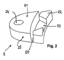
- FIG. 1 shown holding means 2 are In Fig. 2 shown in detail.
- the holding means 2 have a fixing portion 22 and a holding portion 21, wherein between the fixing portion 22 and the holding portion 21, an arcuate predetermined breaking point 20 is mounted in the form of a groove. Adjacent to the predetermined breaking point 20, a recess 23 is provided. The recess 23 engages in the recognizable in detail A corresponding contour 12 a.
- the contour 12 corresponds in shape to the recess 23 and protrudes from the end face of the fastening paragraph 11 out.
- FIG. 1 It can also be seen that in each case two stop ribs 3 delimit a support surface for the holding means 2.
- the holding means 2 are arranged with their recess 23, which are alignment means, so that the predetermined breaking point 20 with the separation point (or gap) between the connector housing 10 and the annular mounting shoulder 11 and the opening 51 of the housing flange 5 is aligned.
- the material thickness in the region of the predetermined breaking point amounts to approximately 10% of the material thickness in the region of the adjacent holding section 21 and also in the region of the fastening section 22.
- the adhesive 2 are bolted to the housing flange 5 in the present embodiment.
- the rear side 5a of the housing flange 5 may also be designed level and closed in order to apply a front-side seal in order to screw it to a corresponding housing opening of a housing.
- the connector 1 After breaking through or cutting through the predetermined breaking points 20, the connector 1 is moved axially against the compression spring, until the mating connector is removed from the connector. In this way damage to the connector 1 butter mattersst be avoided.
- the repair after that is very simple, in which the defective retaining means 2 are replaced and the connector is brought into its original mounting position by means of new retaining means.
Landscapes
- Connector Housings Or Holding Contact Members (AREA)
- Details Of Connecting Devices For Male And Female Coupling (AREA)
Abstract
Description
- Die vorliegende Erfindung betrifft einen Steckverbinder gemäß Patentanspruch 1.
- Die vorliegende Erfindung betrifft daher insbesondere einen Steckverbinder, der mittels eines Haltemittels an einem Gehäuseflansch befestigt ist.
- Im Stand der Technik ist es üblich, Steckverbinder, insbesondere Buchsensteckverbinder an einem Gerät, einer Gehäusewand oder einem Flansch bzw. über einem Gehäuseflansch mit einem Gehäuse zu verbinden.
- In der Regel werden Steckverbinder mit dem Gehäuse mechanisch fest verschraubt.
- Bei diversen Anwendungen ist es allerdings notwendig, dass der Steckverbinder nicht fest mit einer Gehäusewand verbunden ist, sondern gegenüber der Gehäusewand bewegbar ist, sprich im Gehäuse, beweglich angeordnet ist.
- So ist es z. B. bei Steckverbindern notwendig, bei denen regelmäßig eine Kraft auf das Kabel wirkt, dass der Steckverbinder beispielsweise axial federnd im Gehäuse gelagert wird, so dass bei Zug am Steckverbinder über ein Kabel der Steckverbinder entgegen einer Zug- oder Druckfeder im Gehäuse hin- und her federn kann, ohne dass der Steckverbinder beschädigt wird.
- Häufig ist es aber weiter notwendig, dass der Steckverbinder auch gegenüber dem Gehäuse abgedichtet ist. Dies wird beispielsweise dadurch bewerkstelligt, dass zwischen dem beweglichen Steckverbindergehäuse und dem Montagegehäuse in dem der Steckverbinder gelagert ist, eine Dichtung vorgesehen ist, gegen die der Steckverbinder mit seinem Gehäuse dichtend anliegt.
- Wird allerdings der Steckverbinder beispielsweise durch Zug an dem Kabel bewegt, wird dadurch die Dichtung inaktiv bzw. entsteht ein Spalt, durch den Schmutz und Verunreinigungen in das Gehäuseinnere eintreten können.
- Ferner ist von außen nicht ersichtlich, nachdem der Steckverbinder wieder in seine ursprüngliche Position zurückfedert, ob beispielsweise Schmutz auf der Dichtfläche der Dichtung und der Gegendichtfläche anhaftet und daher die Dichtung gänzlich versagt.
- Insbesondere bei Anwendungen, bei den ein Zugfahrzeug einen Anhänger zieht, kann es vorkommen, dass der Steckverbinder starke Beschleunigungen beim Anfahren des Zugfahrzeuges erfährt und der Steckverbinder übermäßig aus seiner Lagerposition betätigt wird, d. h. axial ausgefedert wird, dass entweder der Steckverbinder beschädigt wird oder Funktionsbeeinträchtigungen zu erwarten sind. Besonders problematisch ist das Anfahren, wenn das Zugfahrzeug mit dem Anhänger zwar elektrisch bereits verbunden ist, aber das Verbinden der mechanischen Hängerkupplung vergessen wurde.
- Dann ist es wünschenswert, sofort von Außen zu erkennen, wenn ein solches Ereignis eingetreten ist, dass ggf. mittels einer Wartung oder einer Reparatur der bestimmungsgemäße Zustand wieder hergestellt werden kann.
- Vor diesem Hintergrund ist es Aufgabe der vorliegenden Erfindung, vorbesagte Nachteile zu überwinden und einen Steckverbinder bereitzustellen, der gegenüber einem Gehäuse sicher abdichtet, aber bei Eintreten von hohen mechanischen Kräften nicht beschädigt wird und dennoch das Ereignis einer schädigenden mechanischen Einwirkung erkennbar ist.
- Die vorliegende Aufgabe wird mit den Merkmalen des Patentanspruch 1 gelöst. Vorteilhafte Weiterbildungen der Erfindung sind in den Unteransprüchen angegeben. In den Rahmen der Erfindung fallen auch sämtliche Kombinationen aus zumindest zwei in der Beschreibung, den Ansprüchen und/oder den Zeichnungen angegebenen Merkmalen. Bei angegebenen Wertebereichen sollen auch innerhalb der genannten Grenzen liegende Werte als Grenzwerte offenbart gelten und in beliebiger Kombination beanspruchbar sein.
- Der Erfindung liegt der Gedanke zu Grunde, den Steckverbinder mit seinem Steckverbindergehäuse über jeweils eine Sollbruchstelle aufweisende Haltemittel an einem Gehäuseflansch bzw. an einem Gehäuse zu befestigen. Hierdurch wird sichergestellt, dass bei ungewollt hohen mechanischen Belastungen des Steckverbinders und damit Kräften oberhalb gewisser Grenzwerte die Haltemittel an der Sollbruchstelle durchtrennt werden. Sofern das Steckverbindergehäuse ferner axial an einer Druckfeder hin- und her bewegbar gelagert ist, wird das Steckverbindergehäuse nach Durchtrennen der Haltemittel an ihrer Sollbruchstelle über die Rückstellkraft der Druckfeder in seine ursprüngliche Lage zurückbewegt.
- Auf diese Weise wird sichergestellt, dass das Steckverbindergehäuse nicht beschädigt wird, aber in eine Position in einem Gehäuse oder gegenüber einem Gehäuseflansch gehalten wird, dass es weiterhin funktionsfähig bleibt und ferner anhand der an der Sollbruchstelle durchtrennten Haltemittel unmittelbar erkennbar ist, dass ein den Steckverbinder beeinflussendes oder schädigendes Ereignis eingetreten war.
- Ein Verwender eines solchen Steckverbinders kann also visuell auf einfache Weise erkennen, dass er ggf. den Steckverbinder technisch überprüfen muss und die bestimmungsgemäß "gebrochenen" Haltemittel durch neue Haltemittel ersetzen muss.
- Erfindungsgemäß wird daher ein Steckverbinder mit einem Steckverbindergehäuse bereitgestellt, welches mittels einer Druckfeder gegen eine Rückseite eines Gehäuseflansches axial hin- und her bewegbar gelagert wird, wobei Haltemittel vorgesehen sind, mittels derer das Steckverbindergehäuse an der Vorderseite an dem Gehäuseflansch befestigt wird, wobei ferner die Haltemittel einen Befestigungsabschnitt und einen Halteabschnitt aufweisen und zwischen dem Befestigungsabschnitt und dem Halteabschnitt eine Sollbruchstelle angeordnet ist, so dass eine axiale Auslenkung des Steckverbindergehäuses gegenüber dem Gehäuseflansch nur möglich wird bzw. ist, wenn die Halteabschnitt an der Sollbruchstelle durchtrennt wurden.
- In einer bevorzugten Ausführungsform der Erfindung kann die Sollbruchstelle in Form einer Nut in dem Haltemittel ausgebildet sein. Auf diese Weise kann ein vorzugsweise in der Dicke gleichmäßiges und auf einer gemeinsamen Ebene angebrachtes Haltemittel verwendet werden, dessen als Sollbruchstelle ausgebildete Nut, vorzugsweise an der Trennstelle zwischen dem Steckverbindergehäuse und dem Gehäuseflansch angeordnet ist.
- In einer weiter bevorzugten Ausführungsform weist das Steckverbindergehäuse einen ringförmigen Befestigungsabsatz auf, gegen denen die Halteabschnitte des Haltemittels anliegen.
- Auf diese Weise kann sichergestellt werden, dass der Befestigungsabschnitt am Gehäuseflansch aufliegt, während der Halteabschnitt auf dem Befestigungsabsatzes des Steckverbindergehäuses aufliegt und sich die dazwischenliegende Sollbruchstelle (vorzugsweise der dazwischenliegende als Nut ausgebildete Sollbruchstelle) fluchtend über der Trennstelle zwischen Steckverbindergehäuse und Gehäuseflansch befindet.
- In einer weiter bevorzugten Ausführungsform sind die Haltemittel so ausgebildet, dass benachbart zur Sollbruchstelle eine Ausnehmung in wenigstens einem vorzugsweise allen der Haltemittel als Verdrehschutzmittel ausgebildet ist bzw. sind. Hierdurch kann sichergestellt werden, dass das gegenüber dem Gehäuseflansch beweglich gelagerten, jedoch in seiner Position fixierte Steckverbindergehäuse in seiner Lage in Rotationsrichtung nicht unbeabsichtigt verdreht wird.
- Es ist ferner bevorzugt, benachbart zur Sollbruchstelle eine Ausnehmung so auszubilden, dass diese in eine am Steckverbindergehäuse angeordnete korrespondierende Nut eingreift.
- Als weitere Maßnahme zur Sicherung der Position und/oder des Verdrehschutzes können am Gehäuseflansch eine oder mehrere Anschlagrippen für die Haltemittel benachbart zu diesen so angeordnet werden, dass die Haltemittel gegen ein Verdrehen gegenüber dem Gehäuseflansch gesichert werden und eine definierte Position zum Einbringen der Haltemittel gegeben ist.
- In einer weiter bevorzugten Ausführungsform verfügen die Haltemittel in ihren Befestigungsabschnitten über eine Befestigungsöffnung. Auf diese Weise kann mittels des Haltemittels der Befestigungsabschnitt am Gehäuseflansch verschraubt werden, während der Halteabschnitt den Befestigungsabsatz klemmend gegen die Kraft der Druckfeder lagert.
- In einer weiter bevorzugten Ausführungsform ist die Sollbruchstelle bogenförmig ausgebildet, wobei der Radius, d. h. der Bogenradius der Sollbruchstelle dem Radius des Steckverbindergehäuses im Bereich des ringförmigen Befestigungsabschnittes entspricht. Auf diese Weise kann die bogenförmige Sollbruchstelle fluchtend mit der Außenkontur des ringförmigen Befestigungsabschnittes angeordnet werden.
- Auf diese Weise wird sichergestellt, dass bei axialem Zug mit einer Kraft oberhalb eines definierten Wertes, die die Haltemittel an ihrer Sollbruchstelle durchtrennen lässt, wobei die Kraft exakt an der Sollbruchstelle eingeleitet wird, da sich die Sollbruchstelle fluchtend in der Bewegungsachse des Steckverbindergehäuses befindet.
- In einer besonders bevorzugten Ausführungsform ist die Materialdicke im Bereich der Sollbruchstelle etwa 5 % bis 40 % der Materialstärke im Bereich des Halteabschnittes.
- In einer weiter bevorzugten Ausführungsform entspricht die Materialdicke im Bereich der Sollbruchstelle etwa 5 % bis 20 % der Materialstärke im Vergleich zu der Materialstärke im Bereich des Halteabschnittes.
- In einer weiter bevorzugten Ausführungsform ist die Materialstärke im Bereich des Halteabschnittes identisch mit der Materialstärke im Bereich des Befestigungsabschnittes.
- Auf diese Weise kann sichergestellt werden, dass die Stabilität der Haltemittel ausschließlich über die Dicke und Materialstärke der Sollbruchstelle bestimmt wird, während die Stabilität und Festigkeit der Haltemittel im Bereich des Halteabschnittes und des Befestigungsabschnittes ausreichend hoch ist.
- Entsprechend den zu erwartenden auftretenden mechanischen Einflüssen kann daher der Auslösemechanismus zum Durchtrennen der Sollbruchstelle abhängig von der Materialstärke in der Sollbruchstelle bestimmt werden.
- In dieser Hinsicht können mittels des erfindungsgemäßen Steckverbinders eine Vielzahl unterschiedlicher Applikationen mit unterschiedlich auftretenden und zu erwartenden Kräfte abgebildet werden, bei dem sichergestellt wird, dass bei Auftreten solcher mechanischer Einwirkungen der Steckverbinder bis auf die Haltemittel nicht beschädigt wird.
- Ferner ist optisch unmittelbar erkennbar, dass bei Brechen der Haltemittel an den Sollbruchstellen ein entsprechendes Ereignis eingetreten war.
- Der Verwender des erfindungsgemäßen Steckverbinders kann daher ohne großen Aufwand den Steckverbinder reparieren, indem er die Haltemittel austauscht und gleichzeitig untersuchen, ob der Steckverbinder möglicherweise in folge des Ereignisses beschädigt wurde.
- Besondere Ausgestaltungen der Erfindung befinden sich in den Unteransprüchen. Weitere Vorteile, Ziele und Einzelheiten der Erfindung ergeben sich aus der Beschreibung eines Ausführungsbeispiels anhand der Zeichnungen. In den Zeichnungen zeigt:
- Fig. 1
- eine perspektivische Ansicht eines erfindungsgemäßen Steckverbinders mit einem Detail A;
- Fig. 2
- ein Haltemittel, wie es in der
Fig. 1 verwendet wird. - In den
Figuren 1 und2 ist ein erfindungsgemäßer Steckverbinder 1 gezeigt. Der Steckverbinder 1 verfügt über ein Steckverbindergehäuse 10, das an einer Druckfeder 4 gegen eine Rückseite 5a eines Gehäuseflansches 5 gelagert ist. Der Gehäuseflansch 5 weist Befestigungsöffnungen 50 an seinen Ecken auf. Die Befestigungsöffnungen 50 erstrecken sich von der Vorderseite 5b zur Rückseite 5a des Gehäuseflansches 5. Das Steckverbindergehäuse 10 verfügt über einen ringförmigen Befestigungsabsatz 11. Der Gehäuseflansch 5 verfügt ferner über eine ringförmige Öffnung 51, durch die sich der Steckverbinder hindurch mit seinem Steckverbindergehäuse 10 erstreckt, wobei der ringförmige Befestigungsabsatz 11 mit seiner vorderen Oberfläche 12 mit der Vorderseite 5b des Gehäuseflansches 5 in einer gemeinsamen Ebene liegt. Zwischen dem Befestigungsabsatz 11 und der Öffnung 51 des Gehäuseflansches 5 befindet sich eine Radialdichtung, die das Steckverbindergehäuse 10 gegenüber dem Gehäuseflansch 5 radial abdichtet. Das Steckverbindergehäuse 10 ist mittels Haltemittel 2 am Gehäuseflansch 5 befestigt. Sobald das Steckverbindergehäuse 10 mittels der Haltemittel 2 am Gehäuseflansch 5 befestigt ist, lässt sich der Steckverbinder 1, d. h. das Steckverbindergehäuse 10 nicht mehr in axialer Richtung der Wirkung der Rückstellkraft herausziehen. - Die in
Fig. 1 gezeigten Haltemittel 2 werden InFig. 2 im Detail dargestellt. - Die Haltemittel 2 verfügen über einen Befestigungsabschnitt 22 und einen Halteabschnitt 21, wobei zwischen dem Befestigungsabschnitt 22 und dem Halteabschnitt 21 eine bogenförmige Sollbruchstelle 20 in Form einer Nut angebracht ist. Benachbart zur Sollbruchstelle 20 ist eine Ausnehmung 23 vorgesehen. Die Ausnehmung 23 greift in die im Detail A erkennbare korrespondierende Kontur 12 ein. Die Kontur 12 entspricht in ihrer Form der Ausnehmung 23 und ragt aus der Stirnfläche des Befestigungsabsatzes 11 heraus.
- Im Detail A der
Fig. 1 ist ferner ersichtlich, dass jeweils zwei Anschlagrippen 3 eine Auflagefläche für das Haltemittel 2 begrenzen. - Dabei liegen die Seitenkanten 25 des Haltemittels 2 gegen die Innenflanken der Anschlagrippen 3 an. Dies sichert einen weiteren Verdrehschutz des Steckverbindergehäuses 10 gegen Verdrehen gegenüber dem Gehäuseflansch 5.
- Die Haltemittel 2 sind mit ihrer Ausnehmung 23, welche Ausrichtmittel darstellen, so angeordnet, dass die Sollbruchstelle 20 mit der Trennstelle (bzw. Spalt) zwischen dem Steckverbindergehäuse 10 bzw. dem ringförmigen Befestigungsabsatz 11 und der Öffnung 51 des Gehäuseflansches 5 fluchtet.
- Wie in
Fig. 2 ersichtlich, beträgt die Materialstärke im Bereich der Sollbruchstelle etwa 10 % der Materialstärke im Bereich des daneben liegenden Halteabschnittes 21 sowie ferner im Bereich des Befestigungsabschnittes 22. - Die Haftemittel 2 sind in dem vorliegenden Ausführungsbeispiel mit dem Gehäuseflansch 5 verschraubt. Bevorzugt kann die Rückseite 5a des Gehäuseflansches 5 auch planeben und geschlossen ausgebildet sein, um eine stirnseitige Dichtung aufzubringen, um dieses an einer entsprechenden Gehäuseöffnung eines Gehäuses zu verschrauben.
- Wird an dem erfindungsgemäßen Steckverbinder 1 z. B. mittels massivem, axialem Zug gezogen, z. B. bei beschleunigtem Anfahren eines Zugfahrzeuges, bei dem vergessen wurde, den Anhänger anzukuppeln, so wird eine entsprechende Zugkraft über den korrespondierenden Gegenstecker auf den erfindungsgemäßen Steckverbinder 1 übertragen und der Steckverbinder 1 aus seiner Montageposition herausgerissen, während die Haltemittel 2 an ihrer Sollbruchstelle 20 durchtrennt werden.
- Nach dem Durchbrechen bzw. Durchtrennen der Sollbruchstellen 20 wird der Steckverbinder 1 axial gegen die Druckfeder bewegt, so lange, bis der Gegenstecker aus der Steckverbindung abgezogen ist. Auf diese Weise können Beschädigungen am Steckverbinder 1 weitgehenst vermieden werden. Die Reparatur danach gestaltet sich denkbar einfach, in dem die defekten Haltemittel 2 ausgetauscht werden und der Steckverbinder in seine ursprüngliche Montageposition mittels neuer Haltemittel gebracht wird.
-
- 1
- Steckverbinder
- 2
- Haltemittel
- 3
- Anschlagrippen
- 4
- Druckfeder
- 5
- Gehäuseflansch
- 5a
- Rückseite
- 5b
- Vorderseite
- 10
- Steckverbindergehäuse
- 11
- Befestigungsabsatz
- 12
- Kontur
- 20
- Sollbruchstelle
- 21
- Halteabschnitt
- 22
- Befestigungsabschnitt
- 23
- Ausnehmung
- 24
- Befestigungsöffnung
- 25
- Seitenkante des Haltemittels
- 50
- Befestigungsöffnungen
- 51
- Öffnung
Claims (10)
- Steckverbinder (1) mit einem Steckverbindergehäuse (10), das mittels einer Druckfeder (4) gegen eine Rückseite (5a) eines Gehäuseflansches (5) axial gelagert wird, wobei Haltemittel (2) vorgesehen sind, mittels derer das Steckverbindergehäuse (10) an der Vorderseite (5b) an dem Gehäuseflansch (5) befestigt wird und wobei die Haltemittel (2) einen Befestigungsabschnitt (22) und einen Halteabschnitt (21) aufweisen und zwischen dem Befestigungsabschnitt (22) und dem Halteabschnitt (21) eine Sollbruchstelle (20) angeordnet, so dass eine axiale Bewegung des Steckverbinders (1) entgegen der nur möglich ist, wenn die Haltemittel (2) an der Sollbruchstelle (20) durchtrennt wurden.
- Steckverbinder (1) gemäß Anspruch 1, dadurch gekennzeichnet, dass die Sollbruchstelle (20) in Form einer Nut in dem Haltemittel (2) ausgebildet ist.
- Steckverbinder (1) gemäß Anspruch 1, dadurch gekennzeichnet, dass das Steckverbindergehäuse (10) einen ringförmigen Befestigungsabsatz (11) aufweist, an denen die Halteabschnitte (21) des Haltemittels (2) anliegen.
- Steckverbinder (1) gemäß einem der vorhergehenden Ansprüche 1 bis 3, dadurch gekennzeichnet, dass benachbart zur Sollbruchstelle (20) eine Ausnehmung (23) in wenigstens einem der Haltemittel (2) als Verdrehschutzmittel ausgebildet ist.
- Steckverbinder (1) gemäß wenigstens einem oder mehreren der vorhergehenden Ansprüche, dadurch gekennzeichnet, dass benachbart zur Sollbruchstelle (20) eine Ausnehmung (23) ausgebildet ist, in die eine am Steckverbindergehäuse (10) angeordnete korrespondierende Kontur (12) eingreift.
- Steckverbinder (1) gemäß wenigstens einem oder mehreren der vorhergehenden Ansprüche, dadurch gekennzeichnet, dass am Gehäuseflansch (5) Anschlagrippen (3) für die Haltemittel (2) benachbart zu diesen so angeordnet sind, so dass die Haltemittel (2) gegen ein Verdrehen gegenüber dem Gehäuseflansch (5) gesichert werden.
- Steckverbinder (1) gemäß wenigstens einem oder mehreren der vorhergehenden Ansprüche, dadurch gekennzeichnet, dass die Haltemittel (2) in ihrem Befestigungsabschnitt (22) eine Befestigungsöffnung (24) aufweisen.
- Steckverbinder (1) gemäß wenigstens einem oder mehreren der vorhergehenden Ansprüche, dadurch gekennzeichnet, dass die Sollbruchstelle (20) bogenförmig ausgebildet ist und der Bogenradius dem Radius des Steckverbindergehäuses (10) im Bereich des Spaltes zwischen dem ringförmigen Befestigungsabschnitt (22) und dem Gehäuseflansch (5) entspricht.
- Steckverbinder (1) gemäß Anspruch 7 und 8, dadurch gekennzeichnet, dass die bogenförmige Sollbruchstelle (20) fluchtend mit der dem ringförmigen Spalt zwischen dem Gehäuseflansch (5) angeordnet ist.
- Steckverbinder (1) gemäß wenigstens einem oder mehreren der vorhergehenden Ansprüche, dadurch gekennzeichnet, dass die Materialdicke im Bereich der Sollbruchstelle (20) etwa 5 % bis 20 % der Materialstärke im Bereich des Halteabschnitt (21) entspricht.
Applications Claiming Priority (1)
| Application Number | Priority Date | Filing Date | Title |
|---|---|---|---|
| DE102013008765.1A DE102013008765B4 (de) | 2013-05-23 | 2013-05-23 | Steckverbinder mit trennbaren Haltemitteln |
Publications (2)
| Publication Number | Publication Date |
|---|---|
| EP2806513A1 true EP2806513A1 (de) | 2014-11-26 |
| EP2806513B1 EP2806513B1 (de) | 2016-09-21 |
Family
ID=50440443
Family Applications (1)
| Application Number | Title | Priority Date | Filing Date |
|---|---|---|---|
| EP14001252.7A Active EP2806513B1 (de) | 2013-05-23 | 2014-04-04 | Steckverbinder mit bestimmungsgemäß trennbaren Haltemitteln |
Country Status (2)
| Country | Link |
|---|---|
| EP (1) | EP2806513B1 (de) |
| DE (1) | DE102013008765B4 (de) |
Families Citing this family (2)
| Publication number | Priority date | Publication date | Assignee | Title |
|---|---|---|---|---|
| DE102017115401B4 (de) | 2017-07-10 | 2022-03-24 | Amphenol-Tuchel Electronics Gmbh | Break-Away-Steckdose |
| DE102018101048B4 (de) * | 2018-01-18 | 2019-08-08 | Amphenol Tuchel Industrial GmbH | Steckverbindergehäuse zur Montage an einer Montagewand |
Citations (5)
| Publication number | Priority date | Publication date | Assignee | Title |
|---|---|---|---|---|
| DE1515362A1 (de) * | 1960-07-08 | 1969-12-11 | Amp Inc | Elektrische Mehrfachsteckkupplung mit Einfuehrhuelse |
| US4203638A (en) * | 1978-10-10 | 1980-05-20 | Eagle Electric Mfg. Co., Inc. | Electrical receptacle and grounding strip therefor |
| US4580862A (en) * | 1984-03-26 | 1986-04-08 | Amp Incorporated | Floating coaxial connector |
| EP1250034A2 (de) * | 2001-04-12 | 2002-10-16 | Fujitsu Ten Limited | Elektronische Vorrichtung für Fahrzeuge |
| WO2004097996A1 (en) * | 2003-04-28 | 2004-11-11 | Yazaki Corporation | Attachment structure for electric junction box |
Family Cites Families (6)
| Publication number | Priority date | Publication date | Assignee | Title |
|---|---|---|---|---|
| US4707046A (en) * | 1986-07-10 | 1987-11-17 | Liquidometer Corporation | Safety breakaway electrical connector construction |
| JPH09293553A (ja) * | 1996-04-26 | 1997-11-11 | Sumitomo Wiring Syst Ltd | コネクタ |
| US6083040A (en) * | 1997-07-25 | 2000-07-04 | Itt Manufacturing Enterprises, Inc. | Connector with releasable mounting flange |
| DE10029096A1 (de) * | 2000-06-14 | 2001-12-20 | Andreas Baer | Abriss- und Beschädigungsschutz für flexible Versorgungsleitungen |
| DE202006002712U1 (de) * | 2006-02-21 | 2006-05-11 | Coninvers Elektronische Bauelemente Gmbh | Elektrischer Steckverbinder |
| DE102011018379B4 (de) * | 2011-04-21 | 2012-11-22 | Amphenol-Tuchel Electronics Gmbh | Steckverbindung mit einer Verriegelungsvorrichtung |
-
2013
- 2013-05-23 DE DE102013008765.1A patent/DE102013008765B4/de not_active Expired - Fee Related
-
2014
- 2014-04-04 EP EP14001252.7A patent/EP2806513B1/de active Active
Patent Citations (5)
| Publication number | Priority date | Publication date | Assignee | Title |
|---|---|---|---|---|
| DE1515362A1 (de) * | 1960-07-08 | 1969-12-11 | Amp Inc | Elektrische Mehrfachsteckkupplung mit Einfuehrhuelse |
| US4203638A (en) * | 1978-10-10 | 1980-05-20 | Eagle Electric Mfg. Co., Inc. | Electrical receptacle and grounding strip therefor |
| US4580862A (en) * | 1984-03-26 | 1986-04-08 | Amp Incorporated | Floating coaxial connector |
| EP1250034A2 (de) * | 2001-04-12 | 2002-10-16 | Fujitsu Ten Limited | Elektronische Vorrichtung für Fahrzeuge |
| WO2004097996A1 (en) * | 2003-04-28 | 2004-11-11 | Yazaki Corporation | Attachment structure for electric junction box |
Also Published As
| Publication number | Publication date |
|---|---|
| EP2806513B1 (de) | 2016-09-21 |
| DE102013008765B4 (de) | 2017-06-01 |
| DE102013008765A1 (de) | 2014-11-27 |
Similar Documents
| Publication | Publication Date | Title |
|---|---|---|
| DE102008049258B4 (de) | Kabeldurchführung für Gehäuse elektronischer Komponenten | |
| DE102015122557B4 (de) | Lüftungsvorrichtung, elektrische schaltanlage und druckentlastungskanal | |
| DE102017212009A1 (de) | Zugentlastungstülle | |
| DE102014224932A1 (de) | Haltevorrichtung für eine Schraubenmutter sowie Baueinheit mit einer solchen Haltevorrichtung | |
| DE102009038780B4 (de) | Vorrichtung zur Rohrbruchsicherung | |
| DE102013202792A1 (de) | Verbindungsanordnung zwischen einem radführenden Lenker einer Fahrzeug-Radaufhängung und einem Flansch | |
| EP2806513B1 (de) | Steckverbinder mit bestimmungsgemäß trennbaren Haltemitteln | |
| EP2829781B1 (de) | Presskörper für eine Pressdichtung und Pressdichtung | |
| DE102014113765B4 (de) | Mit Fliessbohrschraube befestigter Erdungsblock | |
| EP2459905A1 (de) | Dichtring und anordnung mit einem dichtring | |
| EP3153755A1 (de) | Quetschflansch mit montagekontrolle | |
| WO2017077017A1 (de) | Klemmmodul zur befestigung an einer tragschiene | |
| DE102015212482A1 (de) | Reparatur-, Umbau- bzw. Nachrüstsatz für eine Rundballenpresse | |
| DE202017105688U1 (de) | Elektronisches Bauteil | |
| DE202016100815U1 (de) | Automatisch ausfahrbare Türspaltdichtung | |
| DE102013207478A1 (de) | Kabelverbinder mit Dichtung und Zugentlastung | |
| DE102019135075A1 (de) | Radialwellendichtung, Faltenbalgflansch und Montageverfahren hierfür | |
| DE202019106038U1 (de) | Kabelanschlussbauteil | |
| DE102019125444A1 (de) | Vorrichtung zur Hindurchführung eines Kabels durch ein Blechelement und Montageverfahren | |
| DE102011079267A1 (de) | Kugelgelenk mit Überlastsicherung | |
| DE102019116242A1 (de) | Gerätekombination zum Schutz von elektrischen Netzen vor Überspannungen oder Überströmen | |
| DE102017130337A1 (de) | Montagevorrichtung zum Einbringen eines Messelements in eine Ausnehmung eines Bauteils | |
| DE102024109759A1 (de) | Dichteinheit für eine Batterievorrichtung und Batterievorrichtung | |
| DE102004045952B3 (de) | Scheibenbremse mit elektromotorisch betätigbarem Nachstellsystem | |
| EP4548432A1 (de) | Erdungsanlagen-anschlussklemmbaugruppe, erdungsanlage sowie verfahren zur herstellung einer klemmverbindung |
Legal Events
| Date | Code | Title | Description |
|---|---|---|---|
| PUAI | Public reference made under article 153(3) epc to a published international application that has entered the european phase |
Free format text: ORIGINAL CODE: 0009012 |
|
| 17P | Request for examination filed |
Effective date: 20140404 |
|
| AK | Designated contracting states |
Kind code of ref document: A1 Designated state(s): AL AT BE BG CH CY CZ DE DK EE ES FI FR GB GR HR HU IE IS IT LI LT LU LV MC MK MT NL NO PL PT RO RS SE SI SK SM TR |
|
| AX | Request for extension of the european patent |
Extension state: BA ME |
|
| R17P | Request for examination filed (corrected) |
Effective date: 20150526 |
|
| RBV | Designated contracting states (corrected) |
Designated state(s): AL AT BE BG CH CY CZ DE DK EE ES FI FR GB GR HR HU IE IS IT LI LT LU LV MC MK MT NL NO PL PT RO RS SE SI SK SM TR |
|
| GRAP | Despatch of communication of intention to grant a patent |
Free format text: ORIGINAL CODE: EPIDOSNIGR1 |
|
| RIC1 | Information provided on ipc code assigned before grant |
Ipc: H01R 13/74 20060101AFI20160318BHEP Ipc: H01R 13/631 20060101ALI20160318BHEP |
|
| INTG | Intention to grant announced |
Effective date: 20160408 |
|
| GRAS | Grant fee paid |
Free format text: ORIGINAL CODE: EPIDOSNIGR3 |
|
| GRAA | (expected) grant |
Free format text: ORIGINAL CODE: 0009210 |
|
| AK | Designated contracting states |
Kind code of ref document: B1 Designated state(s): AL AT BE BG CH CY CZ DE DK EE ES FI FR GB GR HR HU IE IS IT LI LT LU LV MC MK MT NL NO PL PT RO RS SE SI SK SM TR |
|
| REG | Reference to a national code |
Ref country code: GB Ref legal event code: FG4D Free format text: NOT ENGLISH |
|
| REG | Reference to a national code |
Ref country code: CH Ref legal event code: EP |
|
| REG | Reference to a national code |
Ref country code: AT Ref legal event code: REF Ref document number: 831718 Country of ref document: AT Kind code of ref document: T Effective date: 20161015 |
|
| REG | Reference to a national code |
Ref country code: IE Ref legal event code: FG4D Free format text: LANGUAGE OF EP DOCUMENT: GERMAN |
|
| REG | Reference to a national code |
Ref country code: DE Ref legal event code: R082 Ref document number: 502014001466 Country of ref document: DE Representative=s name: PATENTANWAELTE STAEGER & SPERLING PARTNERSCHAF, DE |
|
| REG | Reference to a national code |
Ref country code: DE Ref legal event code: R096 Ref document number: 502014001466 Country of ref document: DE |
|
| REG | Reference to a national code |
Ref country code: LT Ref legal event code: MG4D Ref country code: NL Ref legal event code: MP Effective date: 20160921 |
|
| PG25 | Lapsed in a contracting state [announced via postgrant information from national office to epo] |
Ref country code: RS Free format text: LAPSE BECAUSE OF FAILURE TO SUBMIT A TRANSLATION OF THE DESCRIPTION OR TO PAY THE FEE WITHIN THE PRESCRIBED TIME-LIMIT Effective date: 20160921 Ref country code: FI Free format text: LAPSE BECAUSE OF FAILURE TO SUBMIT A TRANSLATION OF THE DESCRIPTION OR TO PAY THE FEE WITHIN THE PRESCRIBED TIME-LIMIT Effective date: 20160921 Ref country code: NO Free format text: LAPSE BECAUSE OF FAILURE TO SUBMIT A TRANSLATION OF THE DESCRIPTION OR TO PAY THE FEE WITHIN THE PRESCRIBED TIME-LIMIT Effective date: 20161221 Ref country code: LT Free format text: LAPSE BECAUSE OF FAILURE TO SUBMIT A TRANSLATION OF THE DESCRIPTION OR TO PAY THE FEE WITHIN THE PRESCRIBED TIME-LIMIT Effective date: 20160921 |
|
| PG25 | Lapsed in a contracting state [announced via postgrant information from national office to epo] |
Ref country code: NL Free format text: LAPSE BECAUSE OF FAILURE TO SUBMIT A TRANSLATION OF THE DESCRIPTION OR TO PAY THE FEE WITHIN THE PRESCRIBED TIME-LIMIT Effective date: 20160921 Ref country code: LV Free format text: LAPSE BECAUSE OF FAILURE TO SUBMIT A TRANSLATION OF THE DESCRIPTION OR TO PAY THE FEE WITHIN THE PRESCRIBED TIME-LIMIT Effective date: 20160921 Ref country code: GR Free format text: LAPSE BECAUSE OF FAILURE TO SUBMIT A TRANSLATION OF THE DESCRIPTION OR TO PAY THE FEE WITHIN THE PRESCRIBED TIME-LIMIT Effective date: 20161222 Ref country code: SE Free format text: LAPSE BECAUSE OF FAILURE TO SUBMIT A TRANSLATION OF THE DESCRIPTION OR TO PAY THE FEE WITHIN THE PRESCRIBED TIME-LIMIT Effective date: 20160921 |
|
| REG | Reference to a national code |
Ref country code: FR Ref legal event code: PLFP Year of fee payment: 4 |
|
| PG25 | Lapsed in a contracting state [announced via postgrant information from national office to epo] |
Ref country code: RO Free format text: LAPSE BECAUSE OF FAILURE TO SUBMIT A TRANSLATION OF THE DESCRIPTION OR TO PAY THE FEE WITHIN THE PRESCRIBED TIME-LIMIT Effective date: 20160921 Ref country code: EE Free format text: LAPSE BECAUSE OF FAILURE TO SUBMIT A TRANSLATION OF THE DESCRIPTION OR TO PAY THE FEE WITHIN THE PRESCRIBED TIME-LIMIT Effective date: 20160921 |
|
| PG25 | Lapsed in a contracting state [announced via postgrant information from national office to epo] |
Ref country code: CZ Free format text: LAPSE BECAUSE OF FAILURE TO SUBMIT A TRANSLATION OF THE DESCRIPTION OR TO PAY THE FEE WITHIN THE PRESCRIBED TIME-LIMIT Effective date: 20160921 Ref country code: BG Free format text: LAPSE BECAUSE OF FAILURE TO SUBMIT A TRANSLATION OF THE DESCRIPTION OR TO PAY THE FEE WITHIN THE PRESCRIBED TIME-LIMIT Effective date: 20161221 Ref country code: PT Free format text: LAPSE BECAUSE OF FAILURE TO SUBMIT A TRANSLATION OF THE DESCRIPTION OR TO PAY THE FEE WITHIN THE PRESCRIBED TIME-LIMIT Effective date: 20170123 Ref country code: ES Free format text: LAPSE BECAUSE OF FAILURE TO SUBMIT A TRANSLATION OF THE DESCRIPTION OR TO PAY THE FEE WITHIN THE PRESCRIBED TIME-LIMIT Effective date: 20160921 Ref country code: SK Free format text: LAPSE BECAUSE OF FAILURE TO SUBMIT A TRANSLATION OF THE DESCRIPTION OR TO PAY THE FEE WITHIN THE PRESCRIBED TIME-LIMIT Effective date: 20160921 Ref country code: PL Free format text: LAPSE BECAUSE OF FAILURE TO SUBMIT A TRANSLATION OF THE DESCRIPTION OR TO PAY THE FEE WITHIN THE PRESCRIBED TIME-LIMIT Effective date: 20160921 Ref country code: SM Free format text: LAPSE BECAUSE OF FAILURE TO SUBMIT A TRANSLATION OF THE DESCRIPTION OR TO PAY THE FEE WITHIN THE PRESCRIBED TIME-LIMIT Effective date: 20160921 Ref country code: IS Free format text: LAPSE BECAUSE OF FAILURE TO SUBMIT A TRANSLATION OF THE DESCRIPTION OR TO PAY THE FEE WITHIN THE PRESCRIBED TIME-LIMIT Effective date: 20170121 |
|
| REG | Reference to a national code |
Ref country code: DE Ref legal event code: R097 Ref document number: 502014001466 Country of ref document: DE |
|
| PG25 | Lapsed in a contracting state [announced via postgrant information from national office to epo] |
Ref country code: IT Free format text: LAPSE BECAUSE OF FAILURE TO SUBMIT A TRANSLATION OF THE DESCRIPTION OR TO PAY THE FEE WITHIN THE PRESCRIBED TIME-LIMIT Effective date: 20160921 |
|
| PLBE | No opposition filed within time limit |
Free format text: ORIGINAL CODE: 0009261 |
|
| STAA | Information on the status of an ep patent application or granted ep patent |
Free format text: STATUS: NO OPPOSITION FILED WITHIN TIME LIMIT |
|
| PG25 | Lapsed in a contracting state [announced via postgrant information from national office to epo] |
Ref country code: DK Free format text: LAPSE BECAUSE OF FAILURE TO SUBMIT A TRANSLATION OF THE DESCRIPTION OR TO PAY THE FEE WITHIN THE PRESCRIBED TIME-LIMIT Effective date: 20160921 |
|
| 26N | No opposition filed |
Effective date: 20170622 |
|
| PG25 | Lapsed in a contracting state [announced via postgrant information from national office to epo] |
Ref country code: SI Free format text: LAPSE BECAUSE OF FAILURE TO SUBMIT A TRANSLATION OF THE DESCRIPTION OR TO PAY THE FEE WITHIN THE PRESCRIBED TIME-LIMIT Effective date: 20160921 |
|
| REG | Reference to a national code |
Ref country code: CH Ref legal event code: PL |
|
| REG | Reference to a national code |
Ref country code: IE Ref legal event code: MM4A |
|
| PG25 | Lapsed in a contracting state [announced via postgrant information from national office to epo] |
Ref country code: MC Free format text: LAPSE BECAUSE OF FAILURE TO SUBMIT A TRANSLATION OF THE DESCRIPTION OR TO PAY THE FEE WITHIN THE PRESCRIBED TIME-LIMIT Effective date: 20160921 |
|
| PG25 | Lapsed in a contracting state [announced via postgrant information from national office to epo] |
Ref country code: LU Free format text: LAPSE BECAUSE OF NON-PAYMENT OF DUE FEES Effective date: 20170404 Ref country code: LI Free format text: LAPSE BECAUSE OF NON-PAYMENT OF DUE FEES Effective date: 20170430 Ref country code: CH Free format text: LAPSE BECAUSE OF NON-PAYMENT OF DUE FEES Effective date: 20170430 |
|
| REG | Reference to a national code |
Ref country code: BE Ref legal event code: MM Effective date: 20170430 |
|
| REG | Reference to a national code |
Ref country code: FR Ref legal event code: PLFP Year of fee payment: 5 |
|
| PG25 | Lapsed in a contracting state [announced via postgrant information from national office to epo] |
Ref country code: IE Free format text: LAPSE BECAUSE OF NON-PAYMENT OF DUE FEES Effective date: 20170404 |
|
| PG25 | Lapsed in a contracting state [announced via postgrant information from national office to epo] |
Ref country code: BE Free format text: LAPSE BECAUSE OF NON-PAYMENT OF DUE FEES Effective date: 20170430 |
|
| PG25 | Lapsed in a contracting state [announced via postgrant information from national office to epo] |
Ref country code: MT Free format text: LAPSE BECAUSE OF FAILURE TO SUBMIT A TRANSLATION OF THE DESCRIPTION OR TO PAY THE FEE WITHIN THE PRESCRIBED TIME-LIMIT Effective date: 20160921 |
|
| PG25 | Lapsed in a contracting state [announced via postgrant information from national office to epo] |
Ref country code: AL Free format text: LAPSE BECAUSE OF FAILURE TO SUBMIT A TRANSLATION OF THE DESCRIPTION OR TO PAY THE FEE WITHIN THE PRESCRIBED TIME-LIMIT Effective date: 20160921 |
|
| PG25 | Lapsed in a contracting state [announced via postgrant information from national office to epo] |
Ref country code: HU Free format text: LAPSE BECAUSE OF FAILURE TO SUBMIT A TRANSLATION OF THE DESCRIPTION OR TO PAY THE FEE WITHIN THE PRESCRIBED TIME-LIMIT; INVALID AB INITIO Effective date: 20140404 |
|
| PG25 | Lapsed in a contracting state [announced via postgrant information from national office to epo] |
Ref country code: CY Free format text: LAPSE BECAUSE OF FAILURE TO SUBMIT A TRANSLATION OF THE DESCRIPTION OR TO PAY THE FEE WITHIN THE PRESCRIBED TIME-LIMIT Effective date: 20160921 |
|
| PG25 | Lapsed in a contracting state [announced via postgrant information from national office to epo] |
Ref country code: MK Free format text: LAPSE BECAUSE OF FAILURE TO SUBMIT A TRANSLATION OF THE DESCRIPTION OR TO PAY THE FEE WITHIN THE PRESCRIBED TIME-LIMIT Effective date: 20160921 |
|
| PG25 | Lapsed in a contracting state [announced via postgrant information from national office to epo] |
Ref country code: TR Free format text: LAPSE BECAUSE OF FAILURE TO SUBMIT A TRANSLATION OF THE DESCRIPTION OR TO PAY THE FEE WITHIN THE PRESCRIBED TIME-LIMIT Effective date: 20160921 |
|
| PG25 | Lapsed in a contracting state [announced via postgrant information from national office to epo] |
Ref country code: HR Free format text: LAPSE BECAUSE OF FAILURE TO SUBMIT A TRANSLATION OF THE DESCRIPTION OR TO PAY THE FEE WITHIN THE PRESCRIBED TIME-LIMIT Effective date: 20160921 |
|
| REG | Reference to a national code |
Ref country code: AT Ref legal event code: MM01 Ref document number: 831718 Country of ref document: AT Kind code of ref document: T Effective date: 20190404 |
|
| PG25 | Lapsed in a contracting state [announced via postgrant information from national office to epo] |
Ref country code: AT Free format text: LAPSE BECAUSE OF NON-PAYMENT OF DUE FEES Effective date: 20190404 |
|
| P01 | Opt-out of the competence of the unified patent court (upc) registered |
Effective date: 20230613 |
|
| PGFP | Annual fee paid to national office [announced via postgrant information from national office to epo] |
Ref country code: DE Payment date: 20250417 Year of fee payment: 12 |
|
| PGFP | Annual fee paid to national office [announced via postgrant information from national office to epo] |
Ref country code: FR Payment date: 20250422 Year of fee payment: 12 |
|
| PGFP | Annual fee paid to national office [announced via postgrant information from national office to epo] |
Ref country code: GB Payment date: 20260324 Year of fee payment: 13 |