EP2806513A1 - Connecteur comprenant des moyens de retenue pouvant être séparés en fonction de l'utilisation - Google Patents
Connecteur comprenant des moyens de retenue pouvant être séparés en fonction de l'utilisation Download PDFInfo
- Publication number
- EP2806513A1 EP2806513A1 EP14001252.7A EP14001252A EP2806513A1 EP 2806513 A1 EP2806513 A1 EP 2806513A1 EP 14001252 A EP14001252 A EP 14001252A EP 2806513 A1 EP2806513 A1 EP 2806513A1
- Authority
- EP
- European Patent Office
- Prior art keywords
- connector
- housing
- predetermined breaking
- breaking point
- holding means
- Prior art date
- Legal status (The legal status is an assumption and is not a legal conclusion. Google has not performed a legal analysis and makes no representation as to the accuracy of the status listed.)
- Granted
Links
Images

Classifications
-
- H—ELECTRICITY
- H01—ELECTRIC ELEMENTS
- H01R—ELECTRICALLY-CONDUCTIVE CONNECTIONS; STRUCTURAL ASSOCIATIONS OF A PLURALITY OF MUTUALLY-INSULATED ELECTRICAL CONNECTING ELEMENTS; COUPLING DEVICES; CURRENT COLLECTORS
- H01R13/00—Details of coupling devices of the kinds covered by groups H01R12/70 or H01R24/00 - H01R33/00
- H01R13/73—Means for mounting coupling parts to apparatus or structures, e.g. to a wall
- H01R13/74—Means for mounting coupling parts in openings of a panel
- H01R13/748—Means for mounting coupling parts in openings of a panel using one or more screws
-
- H—ELECTRICITY
- H01—ELECTRIC ELEMENTS
- H01R—ELECTRICALLY-CONDUCTIVE CONNECTIONS; STRUCTURAL ASSOCIATIONS OF A PLURALITY OF MUTUALLY-INSULATED ELECTRICAL CONNECTING ELEMENTS; COUPLING DEVICES; CURRENT COLLECTORS
- H01R13/00—Details of coupling devices of the kinds covered by groups H01R12/70 or H01R24/00 - H01R33/00
- H01R13/62—Means for facilitating engagement or disengagement of coupling parts or for holding them in engagement
- H01R13/629—Additional means for facilitating engagement or disengagement of coupling parts, e.g. aligning or guiding means, levers, gas pressure electrical locking indicators, manufacturing tolerances
- H01R13/631—Additional means for facilitating engagement or disengagement of coupling parts, e.g. aligning or guiding means, levers, gas pressure electrical locking indicators, manufacturing tolerances for engagement only
- H01R13/6315—Additional means for facilitating engagement or disengagement of coupling parts, e.g. aligning or guiding means, levers, gas pressure electrical locking indicators, manufacturing tolerances for engagement only allowing relative movement between coupling parts, e.g. floating connection
Definitions
- the present invention relates to a connector according to claim 1.
- the present invention therefore particularly relates to a connector which is fastened by means of a holding means to a housing flange.
- connectors in particular female connectors on a device, a housing wall or a flange or a housing flange with a housing.
- plug connectors are mechanically screwed to the housing.
- the connector is not fixedly connected to a housing wall, but is movable relative to the housing wall, that is, in the housing, is arranged to be movable.
- the connector for example, axially resiliently mounted in the housing so that when train on the connector via a cable of the connector against a tension or compression spring in the housing back and forth can spring, without the connector is damaged.
- the invention is based on the idea to fasten the connector with its connector housing via holding means each having a predetermined breaking point on a housing flange or on a housing. This ensures that at undesired high mechanical loads of the connector and thus forces above certain limits, the holding means are cut at the predetermined breaking point. If the connector housing is further axially movable back and forth on a compression spring, the connector housing is moved back to its predetermined breaking point on the restoring force of the compression spring in its original position after severing the retaining means.
- a user of such a connector can thus visually easily recognize that he must, if necessary, technically check the connector and replace the intended "broken" holding means with new holding means.
- a connector having a connector housing which is axially reciprocally movable by means of a compression spring against a rear side of a housing flange, holding means being provided by which the connector housing is secured to the housing flange at the front, further comprising the retaining means a fastening portion and a holding portion and between the mounting portion and the holding portion a predetermined breaking point is arranged, so that an axial deflection of the connector housing relative to the housing flange is only possible or is when the holding portion were cut at the predetermined breaking point.
- the predetermined breaking point may be formed in the form of a groove in the holding means.
- a preferably uniform in thickness and mounted on a common plane holding means may be used, which is designed as a predetermined breaking point groove, preferably disposed at the separation point between the connector housing and the housing flange.
- the connector housing has an annular attachment paragraph, against which abut the holding portions of the holding means.
- the holding means are formed so that adjacent to the predetermined breaking point a recess in at least one preferably all of the holding means is designed as anti-rotation means or are. This makes it possible to ensure that the connector housing, which is movably mounted relative to the housing flange but is fixed in its position, is not unintentionally rotated in its position in the direction of rotation.
- the position and / or the anti-rotation may be arranged on the housing flange one or more stop ribs for the holding means adjacent thereto so that the holding means are secured against rotation relative to the housing flange and a defined position for introducing the holding means is given ,
- the holding means have a fastening opening in their attachment sections.
- the fastening portion can be screwed to the housing flange, while the holding portion supports the fastening paragraph by clamping against the force of the compression spring.
- the predetermined breaking point is formed arcuate, wherein the radius, ie the radius of curvature of the predetermined breaking point corresponds to the radius of the connector housing in the region of the annular fastening portion. In this way, the arcuate predetermined breaking point can be arranged in alignment with the outer contour of the annular attachment portion.
- the material thickness in the region of the predetermined breaking point is about 5% to 40% of the material thickness in the region of the holding section.
- the material thickness in the region of the predetermined breaking point corresponds to about 5% to 20% of the material thickness in comparison to the material thickness in the region of the holding section.
- the material thickness in the region of the holding section is identical to the material thickness in the region of the fastening section.
- the stability of the holding means is determined solely by the thickness and material thickness of the predetermined breaking point, while the stability and strength of the holding means in the region of the holding portion and the fixing portion is sufficiently high.
- the user of the connector according to the invention can therefore easily repair the connector by exchanging the retaining means and at the same time investigating whether the connector has possibly been damaged as a result of the event.
- the connector 1 has a connector housing 10 which is mounted on a compression spring 4 against a rear side 5a of a housing flange 5.
- the housing flange 5 has attachment openings 50 at its corners.
- the mounting holes 50 extend from the front 5b to the back 5a of the housing flange 5.
- the connector housing 10 has an annular mounting shoulder 11.
- the housing flange 5 also has an annular opening 51 through which the connector extends with its connector housing 10, wherein the annular attachment paragraph 11 lies with its front surface 12 with the front side 5b of the housing flange 5 in a common plane.
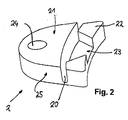
- FIG. 1 shown holding means 2 are In Fig. 2 shown in detail.
- the holding means 2 have a fixing portion 22 and a holding portion 21, wherein between the fixing portion 22 and the holding portion 21, an arcuate predetermined breaking point 20 is mounted in the form of a groove. Adjacent to the predetermined breaking point 20, a recess 23 is provided. The recess 23 engages in the recognizable in detail A corresponding contour 12 a.
- the contour 12 corresponds in shape to the recess 23 and protrudes from the end face of the fastening paragraph 11 out.
- FIG. 1 It can also be seen that in each case two stop ribs 3 delimit a support surface for the holding means 2.
- the holding means 2 are arranged with their recess 23, which are alignment means, so that the predetermined breaking point 20 with the separation point (or gap) between the connector housing 10 and the annular mounting shoulder 11 and the opening 51 of the housing flange 5 is aligned.
- the material thickness in the region of the predetermined breaking point amounts to approximately 10% of the material thickness in the region of the adjacent holding section 21 and also in the region of the fastening section 22.
- the adhesive 2 are bolted to the housing flange 5 in the present embodiment.
- the rear side 5a of the housing flange 5 may also be designed level and closed in order to apply a front-side seal in order to screw it to a corresponding housing opening of a housing.
- the connector 1 After breaking through or cutting through the predetermined breaking points 20, the connector 1 is moved axially against the compression spring, until the mating connector is removed from the connector. In this way damage to the connector 1 butter mattersst be avoided.
- the repair after that is very simple, in which the defective retaining means 2 are replaced and the connector is brought into its original mounting position by means of new retaining means.
Landscapes
- Connector Housings Or Holding Contact Members (AREA)
- Details Of Connecting Devices For Male And Female Coupling (AREA)
Applications Claiming Priority (1)
| Application Number | Priority Date | Filing Date | Title |
|---|---|---|---|
| DE102013008765.1A DE102013008765B4 (de) | 2013-05-23 | 2013-05-23 | Steckverbinder mit trennbaren Haltemitteln |
Publications (2)
| Publication Number | Publication Date |
|---|---|
| EP2806513A1 true EP2806513A1 (fr) | 2014-11-26 |
| EP2806513B1 EP2806513B1 (fr) | 2016-09-21 |
Family
ID=50440443
Family Applications (1)
| Application Number | Title | Priority Date | Filing Date |
|---|---|---|---|
| EP14001252.7A Active EP2806513B1 (fr) | 2013-05-23 | 2014-04-04 | Connecteur comprenant des moyens de retenue pouvant être séparés en fonction de l'utilisation |
Country Status (2)
| Country | Link |
|---|---|
| EP (1) | EP2806513B1 (fr) |
| DE (1) | DE102013008765B4 (fr) |
Families Citing this family (2)
| Publication number | Priority date | Publication date | Assignee | Title |
|---|---|---|---|---|
| DE102017115401B4 (de) | 2017-07-10 | 2022-03-24 | Amphenol-Tuchel Electronics Gmbh | Break-Away-Steckdose |
| DE102018101048B4 (de) * | 2018-01-18 | 2019-08-08 | Amphenol Tuchel Industrial GmbH | Steckverbindergehäuse zur Montage an einer Montagewand |
Citations (5)
| Publication number | Priority date | Publication date | Assignee | Title |
|---|---|---|---|---|
| DE1515362A1 (de) * | 1960-07-08 | 1969-12-11 | Amp Inc | Elektrische Mehrfachsteckkupplung mit Einfuehrhuelse |
| US4203638A (en) * | 1978-10-10 | 1980-05-20 | Eagle Electric Mfg. Co., Inc. | Electrical receptacle and grounding strip therefor |
| US4580862A (en) * | 1984-03-26 | 1986-04-08 | Amp Incorporated | Floating coaxial connector |
| EP1250034A2 (fr) * | 2001-04-12 | 2002-10-16 | Fujitsu Ten Limited | Dispositif électronique pour véhicule |
| WO2004097996A1 (fr) * | 2003-04-28 | 2004-11-11 | Yazaki Corporation | Structure de fixation pour boite de jonction electrique |
Family Cites Families (6)
| Publication number | Priority date | Publication date | Assignee | Title |
|---|---|---|---|---|
| US4707046A (en) * | 1986-07-10 | 1987-11-17 | Liquidometer Corporation | Safety breakaway electrical connector construction |
| JPH09293553A (ja) * | 1996-04-26 | 1997-11-11 | Sumitomo Wiring Syst Ltd | コネクタ |
| US6083040A (en) * | 1997-07-25 | 2000-07-04 | Itt Manufacturing Enterprises, Inc. | Connector with releasable mounting flange |
| DE10029096A1 (de) * | 2000-06-14 | 2001-12-20 | Andreas Baer | Abriss- und Beschädigungsschutz für flexible Versorgungsleitungen |
| DE202006002712U1 (de) * | 2006-02-21 | 2006-05-11 | Coninvers Elektronische Bauelemente Gmbh | Elektrischer Steckverbinder |
| DE102011018379B4 (de) * | 2011-04-21 | 2012-11-22 | Amphenol-Tuchel Electronics Gmbh | Steckverbindung mit einer Verriegelungsvorrichtung |
-
2013
- 2013-05-23 DE DE102013008765.1A patent/DE102013008765B4/de not_active Expired - Fee Related
-
2014
- 2014-04-04 EP EP14001252.7A patent/EP2806513B1/fr active Active
Patent Citations (5)
| Publication number | Priority date | Publication date | Assignee | Title |
|---|---|---|---|---|
| DE1515362A1 (de) * | 1960-07-08 | 1969-12-11 | Amp Inc | Elektrische Mehrfachsteckkupplung mit Einfuehrhuelse |
| US4203638A (en) * | 1978-10-10 | 1980-05-20 | Eagle Electric Mfg. Co., Inc. | Electrical receptacle and grounding strip therefor |
| US4580862A (en) * | 1984-03-26 | 1986-04-08 | Amp Incorporated | Floating coaxial connector |
| EP1250034A2 (fr) * | 2001-04-12 | 2002-10-16 | Fujitsu Ten Limited | Dispositif électronique pour véhicule |
| WO2004097996A1 (fr) * | 2003-04-28 | 2004-11-11 | Yazaki Corporation | Structure de fixation pour boite de jonction electrique |
Also Published As
| Publication number | Publication date |
|---|---|
| EP2806513B1 (fr) | 2016-09-21 |
| DE102013008765B4 (de) | 2017-06-01 |
| DE102013008765A1 (de) | 2014-11-27 |
Similar Documents
| Publication | Publication Date | Title |
|---|---|---|
| DE102008049258B4 (de) | Kabeldurchführung für Gehäuse elektronischer Komponenten | |
| DE102015122557B4 (de) | Lüftungsvorrichtung, elektrische schaltanlage und druckentlastungskanal | |
| DE102017212009A1 (de) | Zugentlastungstülle | |
| DE102014224932A1 (de) | Haltevorrichtung für eine Schraubenmutter sowie Baueinheit mit einer solchen Haltevorrichtung | |
| DE102009038780B4 (de) | Vorrichtung zur Rohrbruchsicherung | |
| DE102013202792A1 (de) | Verbindungsanordnung zwischen einem radführenden Lenker einer Fahrzeug-Radaufhängung und einem Flansch | |
| EP2806513B1 (fr) | Connecteur comprenant des moyens de retenue pouvant être séparés en fonction de l'utilisation | |
| EP2829781B1 (fr) | Corps de compression pour joint de compression et joint de compression | |
| DE102014113765B4 (de) | Mit Fliessbohrschraube befestigter Erdungsblock | |
| EP2459905A1 (fr) | Joint d'étanchéité et agencement doté d'un joint d'étanchéité | |
| EP3153755A1 (fr) | Bride compressible à assemblage contrôlé | |
| WO2017077017A1 (fr) | Module de serrage à fixer à un rail porteur | |
| DE102015212482A1 (de) | Reparatur-, Umbau- bzw. Nachrüstsatz für eine Rundballenpresse | |
| DE202017105688U1 (de) | Elektronisches Bauteil | |
| DE202016100815U1 (de) | Automatisch ausfahrbare Türspaltdichtung | |
| DE102013207478A1 (de) | Kabelverbinder mit Dichtung und Zugentlastung | |
| DE102019135075A1 (de) | Radialwellendichtung, Faltenbalgflansch und Montageverfahren hierfür | |
| DE202019106038U1 (de) | Kabelanschlussbauteil | |
| DE102019125444A1 (de) | Vorrichtung zur Hindurchführung eines Kabels durch ein Blechelement und Montageverfahren | |
| DE102011079267A1 (de) | Kugelgelenk mit Überlastsicherung | |
| DE102019116242A1 (de) | Gerätekombination zum Schutz von elektrischen Netzen vor Überspannungen oder Überströmen | |
| DE102017130337A1 (de) | Montagevorrichtung zum Einbringen eines Messelements in eine Ausnehmung eines Bauteils | |
| DE102024109759A1 (de) | Dichteinheit für eine Batterievorrichtung und Batterievorrichtung | |
| DE102004045952B3 (de) | Scheibenbremse mit elektromotorisch betätigbarem Nachstellsystem | |
| EP4548432A1 (fr) | Ensemble borne de connexion de système de mise à la terre, système de mise à la terre et procédé de production d'une connexion par serrage |
Legal Events
| Date | Code | Title | Description |
|---|---|---|---|
| PUAI | Public reference made under article 153(3) epc to a published international application that has entered the european phase |
Free format text: ORIGINAL CODE: 0009012 |
|
| 17P | Request for examination filed |
Effective date: 20140404 |
|
| AK | Designated contracting states |
Kind code of ref document: A1 Designated state(s): AL AT BE BG CH CY CZ DE DK EE ES FI FR GB GR HR HU IE IS IT LI LT LU LV MC MK MT NL NO PL PT RO RS SE SI SK SM TR |
|
| AX | Request for extension of the european patent |
Extension state: BA ME |
|
| R17P | Request for examination filed (corrected) |
Effective date: 20150526 |
|
| RBV | Designated contracting states (corrected) |
Designated state(s): AL AT BE BG CH CY CZ DE DK EE ES FI FR GB GR HR HU IE IS IT LI LT LU LV MC MK MT NL NO PL PT RO RS SE SI SK SM TR |
|
| GRAP | Despatch of communication of intention to grant a patent |
Free format text: ORIGINAL CODE: EPIDOSNIGR1 |
|
| RIC1 | Information provided on ipc code assigned before grant |
Ipc: H01R 13/74 20060101AFI20160318BHEP Ipc: H01R 13/631 20060101ALI20160318BHEP |
|
| INTG | Intention to grant announced |
Effective date: 20160408 |
|
| GRAS | Grant fee paid |
Free format text: ORIGINAL CODE: EPIDOSNIGR3 |
|
| GRAA | (expected) grant |
Free format text: ORIGINAL CODE: 0009210 |
|
| AK | Designated contracting states |
Kind code of ref document: B1 Designated state(s): AL AT BE BG CH CY CZ DE DK EE ES FI FR GB GR HR HU IE IS IT LI LT LU LV MC MK MT NL NO PL PT RO RS SE SI SK SM TR |
|
| REG | Reference to a national code |
Ref country code: GB Ref legal event code: FG4D Free format text: NOT ENGLISH |
|
| REG | Reference to a national code |
Ref country code: CH Ref legal event code: EP |
|
| REG | Reference to a national code |
Ref country code: AT Ref legal event code: REF Ref document number: 831718 Country of ref document: AT Kind code of ref document: T Effective date: 20161015 |
|
| REG | Reference to a national code |
Ref country code: IE Ref legal event code: FG4D Free format text: LANGUAGE OF EP DOCUMENT: GERMAN |
|
| REG | Reference to a national code |
Ref country code: DE Ref legal event code: R082 Ref document number: 502014001466 Country of ref document: DE Representative=s name: PATENTANWAELTE STAEGER & SPERLING PARTNERSCHAF, DE |
|
| REG | Reference to a national code |
Ref country code: DE Ref legal event code: R096 Ref document number: 502014001466 Country of ref document: DE |
|
| REG | Reference to a national code |
Ref country code: LT Ref legal event code: MG4D Ref country code: NL Ref legal event code: MP Effective date: 20160921 |
|
| PG25 | Lapsed in a contracting state [announced via postgrant information from national office to epo] |
Ref country code: RS Free format text: LAPSE BECAUSE OF FAILURE TO SUBMIT A TRANSLATION OF THE DESCRIPTION OR TO PAY THE FEE WITHIN THE PRESCRIBED TIME-LIMIT Effective date: 20160921 Ref country code: FI Free format text: LAPSE BECAUSE OF FAILURE TO SUBMIT A TRANSLATION OF THE DESCRIPTION OR TO PAY THE FEE WITHIN THE PRESCRIBED TIME-LIMIT Effective date: 20160921 Ref country code: NO Free format text: LAPSE BECAUSE OF FAILURE TO SUBMIT A TRANSLATION OF THE DESCRIPTION OR TO PAY THE FEE WITHIN THE PRESCRIBED TIME-LIMIT Effective date: 20161221 Ref country code: LT Free format text: LAPSE BECAUSE OF FAILURE TO SUBMIT A TRANSLATION OF THE DESCRIPTION OR TO PAY THE FEE WITHIN THE PRESCRIBED TIME-LIMIT Effective date: 20160921 |
|
| PG25 | Lapsed in a contracting state [announced via postgrant information from national office to epo] |
Ref country code: NL Free format text: LAPSE BECAUSE OF FAILURE TO SUBMIT A TRANSLATION OF THE DESCRIPTION OR TO PAY THE FEE WITHIN THE PRESCRIBED TIME-LIMIT Effective date: 20160921 Ref country code: LV Free format text: LAPSE BECAUSE OF FAILURE TO SUBMIT A TRANSLATION OF THE DESCRIPTION OR TO PAY THE FEE WITHIN THE PRESCRIBED TIME-LIMIT Effective date: 20160921 Ref country code: GR Free format text: LAPSE BECAUSE OF FAILURE TO SUBMIT A TRANSLATION OF THE DESCRIPTION OR TO PAY THE FEE WITHIN THE PRESCRIBED TIME-LIMIT Effective date: 20161222 Ref country code: SE Free format text: LAPSE BECAUSE OF FAILURE TO SUBMIT A TRANSLATION OF THE DESCRIPTION OR TO PAY THE FEE WITHIN THE PRESCRIBED TIME-LIMIT Effective date: 20160921 |
|
| REG | Reference to a national code |
Ref country code: FR Ref legal event code: PLFP Year of fee payment: 4 |
|
| PG25 | Lapsed in a contracting state [announced via postgrant information from national office to epo] |
Ref country code: RO Free format text: LAPSE BECAUSE OF FAILURE TO SUBMIT A TRANSLATION OF THE DESCRIPTION OR TO PAY THE FEE WITHIN THE PRESCRIBED TIME-LIMIT Effective date: 20160921 Ref country code: EE Free format text: LAPSE BECAUSE OF FAILURE TO SUBMIT A TRANSLATION OF THE DESCRIPTION OR TO PAY THE FEE WITHIN THE PRESCRIBED TIME-LIMIT Effective date: 20160921 |
|
| PG25 | Lapsed in a contracting state [announced via postgrant information from national office to epo] |
Ref country code: CZ Free format text: LAPSE BECAUSE OF FAILURE TO SUBMIT A TRANSLATION OF THE DESCRIPTION OR TO PAY THE FEE WITHIN THE PRESCRIBED TIME-LIMIT Effective date: 20160921 Ref country code: BG Free format text: LAPSE BECAUSE OF FAILURE TO SUBMIT A TRANSLATION OF THE DESCRIPTION OR TO PAY THE FEE WITHIN THE PRESCRIBED TIME-LIMIT Effective date: 20161221 Ref country code: PT Free format text: LAPSE BECAUSE OF FAILURE TO SUBMIT A TRANSLATION OF THE DESCRIPTION OR TO PAY THE FEE WITHIN THE PRESCRIBED TIME-LIMIT Effective date: 20170123 Ref country code: ES Free format text: LAPSE BECAUSE OF FAILURE TO SUBMIT A TRANSLATION OF THE DESCRIPTION OR TO PAY THE FEE WITHIN THE PRESCRIBED TIME-LIMIT Effective date: 20160921 Ref country code: SK Free format text: LAPSE BECAUSE OF FAILURE TO SUBMIT A TRANSLATION OF THE DESCRIPTION OR TO PAY THE FEE WITHIN THE PRESCRIBED TIME-LIMIT Effective date: 20160921 Ref country code: PL Free format text: LAPSE BECAUSE OF FAILURE TO SUBMIT A TRANSLATION OF THE DESCRIPTION OR TO PAY THE FEE WITHIN THE PRESCRIBED TIME-LIMIT Effective date: 20160921 Ref country code: SM Free format text: LAPSE BECAUSE OF FAILURE TO SUBMIT A TRANSLATION OF THE DESCRIPTION OR TO PAY THE FEE WITHIN THE PRESCRIBED TIME-LIMIT Effective date: 20160921 Ref country code: IS Free format text: LAPSE BECAUSE OF FAILURE TO SUBMIT A TRANSLATION OF THE DESCRIPTION OR TO PAY THE FEE WITHIN THE PRESCRIBED TIME-LIMIT Effective date: 20170121 |
|
| REG | Reference to a national code |
Ref country code: DE Ref legal event code: R097 Ref document number: 502014001466 Country of ref document: DE |
|
| PG25 | Lapsed in a contracting state [announced via postgrant information from national office to epo] |
Ref country code: IT Free format text: LAPSE BECAUSE OF FAILURE TO SUBMIT A TRANSLATION OF THE DESCRIPTION OR TO PAY THE FEE WITHIN THE PRESCRIBED TIME-LIMIT Effective date: 20160921 |
|
| PLBE | No opposition filed within time limit |
Free format text: ORIGINAL CODE: 0009261 |
|
| STAA | Information on the status of an ep patent application or granted ep patent |
Free format text: STATUS: NO OPPOSITION FILED WITHIN TIME LIMIT |
|
| PG25 | Lapsed in a contracting state [announced via postgrant information from national office to epo] |
Ref country code: DK Free format text: LAPSE BECAUSE OF FAILURE TO SUBMIT A TRANSLATION OF THE DESCRIPTION OR TO PAY THE FEE WITHIN THE PRESCRIBED TIME-LIMIT Effective date: 20160921 |
|
| 26N | No opposition filed |
Effective date: 20170622 |
|
| PG25 | Lapsed in a contracting state [announced via postgrant information from national office to epo] |
Ref country code: SI Free format text: LAPSE BECAUSE OF FAILURE TO SUBMIT A TRANSLATION OF THE DESCRIPTION OR TO PAY THE FEE WITHIN THE PRESCRIBED TIME-LIMIT Effective date: 20160921 |
|
| REG | Reference to a national code |
Ref country code: CH Ref legal event code: PL |
|
| REG | Reference to a national code |
Ref country code: IE Ref legal event code: MM4A |
|
| PG25 | Lapsed in a contracting state [announced via postgrant information from national office to epo] |
Ref country code: MC Free format text: LAPSE BECAUSE OF FAILURE TO SUBMIT A TRANSLATION OF THE DESCRIPTION OR TO PAY THE FEE WITHIN THE PRESCRIBED TIME-LIMIT Effective date: 20160921 |
|
| PG25 | Lapsed in a contracting state [announced via postgrant information from national office to epo] |
Ref country code: LU Free format text: LAPSE BECAUSE OF NON-PAYMENT OF DUE FEES Effective date: 20170404 Ref country code: LI Free format text: LAPSE BECAUSE OF NON-PAYMENT OF DUE FEES Effective date: 20170430 Ref country code: CH Free format text: LAPSE BECAUSE OF NON-PAYMENT OF DUE FEES Effective date: 20170430 |
|
| REG | Reference to a national code |
Ref country code: BE Ref legal event code: MM Effective date: 20170430 |
|
| REG | Reference to a national code |
Ref country code: FR Ref legal event code: PLFP Year of fee payment: 5 |
|
| PG25 | Lapsed in a contracting state [announced via postgrant information from national office to epo] |
Ref country code: IE Free format text: LAPSE BECAUSE OF NON-PAYMENT OF DUE FEES Effective date: 20170404 |
|
| PG25 | Lapsed in a contracting state [announced via postgrant information from national office to epo] |
Ref country code: BE Free format text: LAPSE BECAUSE OF NON-PAYMENT OF DUE FEES Effective date: 20170430 |
|
| PG25 | Lapsed in a contracting state [announced via postgrant information from national office to epo] |
Ref country code: MT Free format text: LAPSE BECAUSE OF FAILURE TO SUBMIT A TRANSLATION OF THE DESCRIPTION OR TO PAY THE FEE WITHIN THE PRESCRIBED TIME-LIMIT Effective date: 20160921 |
|
| PG25 | Lapsed in a contracting state [announced via postgrant information from national office to epo] |
Ref country code: AL Free format text: LAPSE BECAUSE OF FAILURE TO SUBMIT A TRANSLATION OF THE DESCRIPTION OR TO PAY THE FEE WITHIN THE PRESCRIBED TIME-LIMIT Effective date: 20160921 |
|
| PG25 | Lapsed in a contracting state [announced via postgrant information from national office to epo] |
Ref country code: HU Free format text: LAPSE BECAUSE OF FAILURE TO SUBMIT A TRANSLATION OF THE DESCRIPTION OR TO PAY THE FEE WITHIN THE PRESCRIBED TIME-LIMIT; INVALID AB INITIO Effective date: 20140404 |
|
| PG25 | Lapsed in a contracting state [announced via postgrant information from national office to epo] |
Ref country code: CY Free format text: LAPSE BECAUSE OF FAILURE TO SUBMIT A TRANSLATION OF THE DESCRIPTION OR TO PAY THE FEE WITHIN THE PRESCRIBED TIME-LIMIT Effective date: 20160921 |
|
| PG25 | Lapsed in a contracting state [announced via postgrant information from national office to epo] |
Ref country code: MK Free format text: LAPSE BECAUSE OF FAILURE TO SUBMIT A TRANSLATION OF THE DESCRIPTION OR TO PAY THE FEE WITHIN THE PRESCRIBED TIME-LIMIT Effective date: 20160921 |
|
| PG25 | Lapsed in a contracting state [announced via postgrant information from national office to epo] |
Ref country code: TR Free format text: LAPSE BECAUSE OF FAILURE TO SUBMIT A TRANSLATION OF THE DESCRIPTION OR TO PAY THE FEE WITHIN THE PRESCRIBED TIME-LIMIT Effective date: 20160921 |
|
| PG25 | Lapsed in a contracting state [announced via postgrant information from national office to epo] |
Ref country code: HR Free format text: LAPSE BECAUSE OF FAILURE TO SUBMIT A TRANSLATION OF THE DESCRIPTION OR TO PAY THE FEE WITHIN THE PRESCRIBED TIME-LIMIT Effective date: 20160921 |
|
| REG | Reference to a national code |
Ref country code: AT Ref legal event code: MM01 Ref document number: 831718 Country of ref document: AT Kind code of ref document: T Effective date: 20190404 |
|
| PG25 | Lapsed in a contracting state [announced via postgrant information from national office to epo] |
Ref country code: AT Free format text: LAPSE BECAUSE OF NON-PAYMENT OF DUE FEES Effective date: 20190404 |
|
| P01 | Opt-out of the competence of the unified patent court (upc) registered |
Effective date: 20230613 |
|
| PGFP | Annual fee paid to national office [announced via postgrant information from national office to epo] |
Ref country code: DE Payment date: 20250417 Year of fee payment: 12 |
|
| PGFP | Annual fee paid to national office [announced via postgrant information from national office to epo] |
Ref country code: FR Payment date: 20250422 Year of fee payment: 12 |
|
| PGFP | Annual fee paid to national office [announced via postgrant information from national office to epo] |
Ref country code: GB Payment date: 20260324 Year of fee payment: 13 |