EP2807106B1 - Vorrichtung zur befestigung einer hebemaschine für einen aufzug und befestigungsanordnung - Google Patents
Vorrichtung zur befestigung einer hebemaschine für einen aufzug und befestigungsanordnung Download PDFInfo
- Publication number
- EP2807106B1 EP2807106B1 EP13741110.4A EP13741110A EP2807106B1 EP 2807106 B1 EP2807106 B1 EP 2807106B1 EP 13741110 A EP13741110 A EP 13741110A EP 2807106 B1 EP2807106 B1 EP 2807106B1
- Authority
- EP
- European Patent Office
- Prior art keywords
- elevator
- fixing
- machine station
- guide rail
- guide rails
- Prior art date
- Legal status (The legal status is an assumption and is not a legal conclusion. Google has not performed a legal analysis and makes no representation as to the accuracy of the status listed.)
- Not-in-force
Links
Images


Classifications
-
- B—PERFORMING OPERATIONS; TRANSPORTING
- B66—HOISTING; LIFTING; HAULING
- B66B—ELEVATORS; ESCALATORS OR MOVING WALKWAYS
- B66B11/00—Main component parts of lifts in, or associated with, buildings or other structures
- B66B11/0035—Arrangement of driving gear, e.g. location or support
- B66B11/0045—Arrangement of driving gear, e.g. location or support in the hoistway
-
- B—PERFORMING OPERATIONS; TRANSPORTING
- B66—HOISTING; LIFTING; HAULING
- B66B—ELEVATORS; ESCALATORS OR MOVING WALKWAYS
- B66B11/00—Main component parts of lifts in, or associated with, buildings or other structures
- B66B11/0065—Roping
- B66B11/008—Roping with hoisting rope or cable operated by frictional engagement with a winding drum or sheave
- B66B11/009—Roping with hoisting rope or cable operated by frictional engagement with a winding drum or sheave with separate traction and suspension ropes
Definitions
- the object of the invention is an elevator and its apparatus for fixing a hoisting machine of the elevator as presented in the preamble of claim 1.
- an elevator machine is installed into its position as separate parts, e.g. in such a way that at first the precise positions of the guide rails of the elevator car are measured and marked and generally the car guide rails are also fixed into position. After that the other components that belong in connection with the elevator machine can be disposed in the correct positions in relation to the car guide rails.
- the machine bedplate is installed in its position in relation to the car guide rails, after which the elevator machine, with its traction sheave and diverting pulleys, is installed, and so on until all the necessary components are disposed in their correct positions.
- Installation work of this kind is extremely time-consuming, because a lot of measuring and plumbing is needed for getting the components precisely into their correct positions. Additionally, measuring errors often also occur, which can result in the elevator installation not functioning in the best possible way, and installation errors and measuring errors can cause damage to the elevator structures as well as produce noise problems and other problems. The additional repairs needed cause operating disruptions and extra costs.
- a template can also be used as an aid, which template is first placed on the base of the hoistway and the components are then disposed on top of the template in the positions indicated by the template.
- document JP 200247559 shows a machine bedplate to be installed on the bottom of a shaft, on which bedplate a hoisting machine is to be installed along with pulleys as needed for guiding the supporting ropes away from the bedplate.
- document JP 2001 048450 shows a mounting base for installing a hoisting machine along with additional components at the top end of an elevator shaft, which mounting base is slidably connected to the guiderails for being able to lower the same by means of a spindle when maintenance work is necessary.
- document US 2010/084224 on which the preamble of claim 1 is based, shows an elevator system the machine of which being positioned above a car and being mounted on an overhead structure that is supported only by guide rail units. This mounting arrangement shall avoid contacts between the overhead structure and the elevator hoistway in the building.
- the aim of the present invention is to eliminate the aforementioned drawbacks and to achieve an inexpensive apparatus, which can be precisely and rapidly installed and that is easily implemented, for installing and fixing a hoisting machine of an elevator.
- a type of fixing arrangement to be used in the installation of an elevator is gained, wherein the hoisting machine of the elevator, with its components, and the guide rails of the elevator car can be easily interpositioned with each other in such a way that after the plumbing of the guide rails of the car other measurements and plumbings are not necessarily needed.
- the locations of the elevator machine and of the components of the elevator in the layout of the elevator are automatically determined on the basis of the location of the guide rails of the elevator car as well as on the basis of the shape, dimensioning and manufacturing tolerances of the machine station according to the invention and of the machine station brackets as well as of the guide rail brackets.
- the apparatus according to the invention is characterized by what is disclosed in the characterization part of claim 1.
- Other embodiments of the invention are characterized by what is disclosed in the other claims.
- One advantage, among others, of the solution according to the invention is that by means of it the rapid, easy and reliable installation of an elevator machine precisely into its own position is enabled without time-consuming measuring and plumbing.
- one advantage is that in the installation errors do not occur in the location position of the elevator machine and of the elevator components, but instead all the location positions are automatically determined on the basis of the location of the guide rails of the elevator car as well as on the basis of the shape, dimensioning and manufacturing tolerances of the machine station and of the machine station brackets as well as of the guide rail brackets.
- Another advantage is that since no fixings need to be made in the floor of the hoistway, the solution according to the invention can also be used in old elevator hoistways, in which the resilience of the floor is not certain.
- Another advantage is cost savings enabled by the solution, owing to the speed and ease of installation.
- an elevator comprising an elevator car and one or more counterweights or compensating weights suspended by at least one suspension member, such as a rope or a belt, and moved by a traction member, e.g. a belt, that is separate from the suspension member and driven by at least one traction sheave, comprises a machine station, wherein the locations of the traction sheave and the motor or machine rotating the traction sheave, and the passage of the traction member are positioned e.g. by the aid of one or more diverting pulleys.
- the machine station is fixed to a bracket, which positions the location of the guide rail of the elevator car, even more preferably to brackets, which position the locations of the guide rails of the elevator car.
- brackets and the machine station together determine the interpositioning of the traction sheave and the motor or machine rotating the traction sheave, and the traction member and the guide rails of the elevator car.
- the brackets for positioning the location of the guide rail of the elevator car are thus used to fix the machine bedplate into its position.
- the machine bedplate can in this way be fixed e.g. to the walls or floor, or otherwise, of the elevator hoistway.
- a fairly advantageous method is to fix at least one, possibly two or more, bottom parts of the guide rails belonging to the elevator into their position and then to use one or more of the guide rails thus fixed as an aid in configuring the location of the machine station.
- the supporting of the machine station can be arranged entirely by the aid of the elevator guide rails or counterweight guide rails.
- the supporting can also be arranged by the aid of a fixing means, such as e.g. a wall bracket, that is common to a guide rail and to the machine station.
- the solution according to the invention is at least for an elevator car 1 configured to move reciprocally in an elevator hoistway and at least one or more counterweights or compensating weights 2a, 2b, which are for their part connected to support the elevator car 1 by the aid of suspension members 3, such as belts or ropes, and also by the aid of e.g. diverting pulleys 4 in the top part of the elevator hoistway, e.g. mounted on bearings on the guide rails 11 of the elevator car 1.
- the apparatus comprises a machine station 6 with its brackets 8, that is provided with at least one traction sheave 5 or corresponding and with a hoisting motor 5a, with a brake 5b, with an encoder 5c as well as with other components needed for the hoisting machine, to which brackets 8 the lowest wall bracket functioning as a fixing part 8c of the guide rail 11 of the elevator car is also connected.
- Means enabling a weighing function are also preferably connected to the joint between the brake 5b and the frame of the machine station 6.
- the apparatus according to the invention also comprises at least one or more traction members 7a, 7b, such as ropes or belts, that are fully separate from the suspension members 3, which traction members are configured to transmit the rotational movement of the traction sheave 5 into linear movement of the elevator car 1 and of the compensating weights 2a, 2b.
- traction members 7a, 7b such as ropes or belts
- a rope clamp 3a or corresponding locking means is fixed to the top part of the elevator car 1, with which rope clamp each suspension member 3 is locked into position on the top part of the elevator car 1, e.g. during servicing work on the elevator.
- the aforementioned two or more compensating weights 2a, 2b enable an essentially easy layout in elevator design.
- the layout also brings various space benefits.
- one layout solution can be e.g. the type of layout in which, when viewed from above, at the center of the elevator hoistway is a plane formed by the car guide rails 11 of the elevator and around this plane are four corners for different structural solutions.
- two corners are used for the compensating weights 2a, 2b and their guide rails 27, one corner is used for safety devices, mainly e.g. for an overspeed governor, and one corner is used for other devices, such as for the trailing cables, et cetera.
- Fig. 1 presents a simplified and diagrammatic side view of one elevator arrangement provided with at least two compensating weights, in which elevator arrangement a machine station 6 according to the invention and its fixing arrangement are used
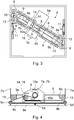
- Figs. 2 and 3 present simplified top views of an elevator arrangement according to Fig. 1 , in the bottom part of the elevator hoistway
- Fig. 4 presents the machine station according to Fig. 3 as viewed directly from the side, sectioned from the center, simplified, and without the brackets 8 of the machine station 6.
- Fig. 2 presents a top view of one arrangement according to the invention for disposing the compensating weights 2a, 2b in the elevator hoistway.
- the compensating weights 2a, 2b are disposed on opposite sides of the elevator car 1 and on different sides of the guide rail line of the elevator car 1 to each other, in which case the suspension of the elevator car 1 and of the compensating weights 2a, 2b is very symmetrical and does not produce any additional stresses e.g. on the guide rails 11 of the elevator car. This is an extremely advantageous layout option if it is only possible.
- the elevator arrangement according to Figs. 1-4 comprises two compensating weights 2a and 2b, both of which are connected to the elevator car 1 by the aid of common suspension members 3.
- the suspension member 3 is fixed at its first end to a first compensating weight 2a functioning as a counterweight, and passes over a first diverting pulley 4 in the top part of the elevator hoistway or in the machine room and onwards above the elevator car 1 under the diverting pulleys 4c and 4d disposed on the elevator car 1, and ascends upwards again and passes over a second diverting pulley 4 in the top part of the elevator hoistway or in a machine room and descends downwards to a second compensating weight 2b functioning as a counterweight, to which compensating weight the suspension member 3 is fixed at its second end.
- the diverting pulleys 4 are preferably disposed e.g. on the top ends of the guide rails 11 of the elevator car 1, in which case the guide rails 11 take the forces produced by moving the elevator car e.g. via their guide rail brackets into the walls of the elevator hoistway or into other strong structures. There are, however, also other suitable location position points.
- a machine station 6 comprising a hoisting machine and means connected to it, said machine station being provided with a one-piece or two-piece traction sheave 5, is configured to move the elevator car 1, which machine station is preferably e.g. of modular structure and is disposed supported on its brackets 8 in the bottom part of the elevator hoistway, e.g. on the base of the elevator hoistway or right in the proximity of the base.
- installation of the machine station 6 is easy, and long electric cables from the bottom part of the building to the hoisting machine and to the control cabinet are not needed.
- At least one humidity sensor which is arranged to issue an alarm and if necessary to stop the elevator if excessive water comes onto the base of the hoistway, is disposed on the base of the hoistway. In this way the elevator machine and the electrical components of the elevator can be protected from excessive humidity.
- the modular machine station 6 with hoisting machine, support structures and diverting pulleys 13-15 and with its traction sheave 5, is at some certain angle with respect to the mutual guide rail line of the guide rails 11 of the elevator car 1. This angle can vary, depending on the respective elevator layout solution.
- the machine station 6, with associated support structures is fixed at its ends to brackets 8, which are further fixed e.g. to the wall of the elevator hoistway in such a way that the wall structures receive the forces produced by moving the elevator car.
- the top surface of the brackets 8 also comprises buffers 12 for the compensating weights 2a, 2b.
- the support structure of the machine station 6 is composed of e.g. two parallel frame beams 9 that are at a distance from each other and in the longitudinal direction of the machine station 6, the structure of which frame beam 9 is described in more detail in Figs. 7-8 , and of two parallel frame plates 10 of the motor 5a that are at a distance from each other and in the longitudinal direction of the machine station 6 and are fixed to the frame beams 9, of which the first frame plate is fixed e.g. with bolts and nuts to a first frame beam 9 of the machine station 6 and the second is fixed e.g. with bolts and nuts to a second frame beam 9 of the machine station 6.
- the frame plates 10 of the motor also have precisely dimensioned and positioned holes for the shafts of the traction sheave 5 and of the diverting pulleys 14, 16 as well as fixing holes 10b for fixing the frame plates 10 precisely into their correct location on the frame beams 9.
- the frame beams 9 and the frame plates 10 of the motor are additionally supported on each other by the aid of support plates 9a and 10a, of which support plates for the sake of clarity not all are presented in the figures.
- the guide rails 11 of the elevator car 1 are fixed at their bottom ends to the same brackets 8, which are made to be dimensionally precise in such a way that the guide rails 11 can be easily and precisely positioned in their correct locations, after which the entire machine station 6, with all its components, is in precisely the correct location position with regard to the operation of the whole elevator.
- the positioning of the machine station 6 is determined according to the location of the guide rail 11 of the elevator car 1 and the fixing parts of the machine station 6 without separate plumbing at the same time as only the guide rails 11 are plumbed.
- Fig. 4 The passage of the traction members 7a, 7b on the diverting pulleys and traction sheaves of the machine station 6 is seen from Fig. 4 .
- each compensating weight separately its own traction member 7a, 7b is disposed between the bottom part of the compensating weights 2a, 2b and the bottom part of the elevator car 1, which traction member receives its movement transmission force from the traction sheave 5 of the hoisting machine of the machine station 6, said traction sheave rotating on an essentially vertical plane.
- the first traction member 7a is fixed at its first end to a first compensating weight 2a, is configured to leave the compensating weight 2a and go downwards and is led to pass around the bottom of a first diverting pulley 13 on a first side of the traction sheave 5, after which the traction member 7a is led past the traction sheave 5 of the hoisting machine of the machine station 6 fitted below the elevator car 1 below the traction sheave 5 from the first side to the second side of the traction sheave and onwards below a second diverting pulley 14 on the second side of the traction sheave 5 and disposed in connection with the hoisting machine, around the diverting pulley and back towards the traction sheave 5 of the hoisting machine, after passing around the bottom of which the traction member 7a is led upwards from the first side of the traction sheave 5 to a fixing point in connection with the elevator car 1, to which fixing point the second end of the traction member 7a is fixed.
- the second traction member 7b is configured to travel from the second compensating weight 2b via the traction sheave 5 to the elevator car 1 in such a way that the second traction member 7b is fixed at its first end to the second compensating weight 2b, is configured to leave the compensating weight 2b and go downwards and is led to pass around the bottom of at least one third diverting pulley 15 on the second side of the traction sheave 5, after which the traction member 7b is led over a fourth diverting pulley 16 on the second side of the traction sheave 5 to the traction sheave 5 of the hoisting machine disposed below the elevator car 1 from the second side of the traction sheave 5 and is configured to pass around the bottom of the traction sheave 5 and to ascend after this from the first side of the traction sheave 5 to the elevator car 1, to the fixing point in connection with which elevator car the second end of the traction member 7b is fixed.
- the contact surface of the traction sheave 5 is so wide that both the traction members 7a, 7b fit side-by-side onto the contact surface of the traction sheave 5 without interfering with each other. In this way one and the same hoisting machine of a machine station 6 and also one and the same traction sheave 5 give to both the traction members 7a, 7b a force producing linear movement of the elevator car 1 and of the compensating weights 2a, 2b.
- a second alternative is a structural solution, in which the same traction shaft has two parallel traction sheaves 5.
- Fig. 4 also presents fixing plates 9b functioning as the fixing means of a machine station 6, which fixing plates are fixed e.g. with screw fixings to the base plate 9e of the machine station 6 at both ends of the machine station 6.
- the fixing plates 9b have in the outer ends fixing holes, via which the machine station 6 is fixed at its ends to the brackets 8 via screws 9d functioning as fixing means and via insulation means 9c that damp sound and vibration.
- the machine station 6 itself does not in this embodiment rest on the floor of the elevator hoistway, but instead on the walls of the elevator hoistway or on other corresponding supporting structures, and the screws 9d, onto the support of which the machine station can be temporarily lowered, are off the floor in the machine station 6 when said station is fixed into its position.
- a flexible, e.g. spring-action, support element 5d is disposed below the motor 5a, with which support element the torsion produced by the mass of the motor 5a in the frame beams 9 of the machine station 6 is, if necessary, compensated.
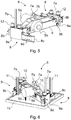
- Figs. 5 and 6 present an oblique top view and from two different directions from the side of a machine station 6 according to the invention, with brackets 8, fixed into its position in the bottom part of the elevator hoistway.
- brackets 8 of the machine station 6 are composed of at least e.g.
- a support part 8a of the machine station a wall bracket 8b of the bracket 8 and, in addition, a fixing part 8c of the guide rail 11 of the car, said fixing part to be fixed to the support part 8a of the machine station and comprising a plurality of fixing holes 8d of the guide rail 11 of the car that are precisely situated in the correct positions, which fixing holes function as the fixing points of the guide rail 11.
- the brackets 8 and their parts 8a-8d are made to precisely the correct dimensions and shapes, which enables the position of the brackets 8, and thereby of the whole machine station 6 as well as of the other elevator structures above the machine station 6, in the elevator hoistway in relation to the layout of the elevator to be determined directly according to the exact location position of the car guide rails 11 by fixing the brackets 8 to the car guide rails 11.
- the fixing holes 8d in the fixing part 8c of a car guide rail 11 form precise fixing points for the car guide rails 11, in which case the same brackets 8 and fixing parts 8c can be used in all elevator hoistways, even if the compensating weights 2a, 2b in different hoistways were of different widths.
- Fig. 7 presents a simplified side view of one frame beam 9 of the frame part of a machine station 6, the base part 9e with the fixing plates 9b and the fixing means 9d and the fixing insulations 9c of the machine station.
- the frame beam 9 is e.g. a metal plate reinforced with bendings, in the center part of which beam is an opening 9f that is almost the height of the frame beam 9 and is open at the top, at the point of which opening the fixing plates 10 of the motor and the motor 5a with machine can be disposed.
- the frame beam 9 comprises a plurality of fixing holes 9g for fixing the fixing plates 10 of the motor to the frame beam 9 and holes 9h in the ends of the frame beam 9 for the shafts of the diverting pulleys 13 and 15.
- the shafts of the diverting pulleys 14 and 16 and of the traction sheave 5 are fitted in connection with the fixing plates 10 of the motor.
- Fig. 8 presents a top view of one end of the frame part of a machine station 6 and the fixing plate 9b of the machine station 6 with the fixing means 9d and fixing insulations 9c of the machine station 6.
- the fixing plates 9b are fixed at the fixing holes 9i to the base part 9e of the machine station 6 e.g. by the aid of screws 9j, one of which screws is removed in Fig. 8 .
- Fig. 8a presents a top view of the fixing plate 9b, without fixing means, of the machine station 6 presented in Fig. 8 .
- the outer end of the fixing plate 9b has a first round fixing hole 9k and a second elongated fixing hole 9k, via which holes the machine station 6 is fixed to the brackets 8 by the aid of bolts and nuts functioning as fixing means 9d.
- the round hole 9k is situated at the point of the corresponding round hole in the bracket 8, which is disposed in such a way that the aforementioned hole in the bracket and the round hole 9k function as a hinge point at the point of the center point of the cross-section of the traction member 7a, 7b ascending to the compensating weight 2a, 2b.
- the elongated hole 9m of the fixing part allows a change in the angle of the fixing of the machine station 6 with different widths of the elevator hoistway.
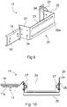
- Figs. 9 and 10 present a guide rail bracket 17 to be disposed higher up in the elevator hoistway to be used in the fixing arrangement according to the invention.
- the guide rail bracket 17 is a bracket fabricated e.g. from one metal plate by bending and otherwise machining, the first end of which bracket comprises an essentially planar fixing part 18 with fixing holes 19 for the guide rails 11 of the elevator car 1.
- the second end of the guide rail bracket 17 is configured to form a mounting base 20 for the guide rails of the compensating weight.
- the mounting base 20 comprises a first essentially planar fixing part 21 and a second essentially planar fixing part 22 for the guide rails of the compensating weight, which fixing parts 21, 22 are essentially in the same direction as each other.
- the fixing parts 21, 22 are rigidly connected to each other with the back part 23 of the guide rail bracket 17, which back part is essentially orthogonal to the plane of the fixing parts 21, 22.
- the fixing parts 21, 22 have fixing holes 24 for fixing the guide rails of the compensating weight to the guide rail bracket 17 and, in addition, the fixing part 22 has, if necessary, extra fixing holes for fixing a separate wall bracket 25 to the second end of the guide rail bracket 17.
- a guide rail bracket 17 is fixed by means of a wall bracket 25 e.g. to the wall of the elevator hoistway.
- the wall bracket 25 correspondingly has elongated fixing holes 26, by means of which the wall bracket 25 can be fixed to a suitable location in a manner allowing adjustment, both to the guide rail bracket 17 and to the wall of the elevator hoistway or corresponding fixing location.
- the mounting base 20 of the guide rail bracket 17 has fixing holes 20a for the cover plate 29 presented in Fig. 10 .
- Fig. 10 presents a top view of a compensating weight 2a, which is drawn with a dot-and-dash line, a detached cover plate 29 to be disposed in front of the path of travel of the compensating weight 2a and to be fixed to the guide rail bracket 17, and a guide rail bracket 17 to be used in the fixing arrangement according to the invention provided with the guide rails 11 of the elevator car 1.
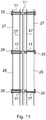
- Fig. 11 presents three guide rail brackets 17, as viewed from the direction of the side wall of the elevator hoistway, in their position and a part of both the compensating weight guide rails 27 and of the guide rails 11 of the car 1 of the elevator.
- the compensating weights are not presented in Fig. 11 , but a cover plate 29 is fixed in front of the guide rails 27 of the compensating weight, between the guide rails 27 and the elevator car 1, which cover plate is fixed e.g. at both ends to the fixing holes 20a of the mounting base 20 of the guide rail bracket 17.
- the cover plate 29 functions as a protective plate e.g. when an elevator fitter or service person is in the elevator hoistway and drives the elevator.
- the cover plate 29 functions as a noise-damping restraint when installed at a point in which the elevator car 1 and the compensating weights 2a, 2b meet in the elevator hoistway.
- the shape and dimensioning of the guide rail brackets 17, as well as the manufacturing tolerances and the positions and dimensioning of the fixing holes 24 in the guide rail brackets 17 as well as of the fixing holes of the compensating weight guide rails 27, are configured to be such that the position of the compensating weight guide rails 27 is ready in the guide rail brackets 17 to a sufficient degree of accuracy and by fixing the guide rail brackets 17 to the guide rails 11 of the elevator car 1 on a fixing point for the guide rail 11, the compensating weight guide rails 27 can be fixed sufficiently precisely into their position without separate plumbing, because it is sufficient that only the guide rails 11 of the elevator car 1 are plumbed.
- the guide rail bracket 17 comprises means for fixing the guide rail bracket 17 to the guide rail 11 of the elevator car 1 and for fixing the compensating weight guide rails 27 to the guide rail bracket 17 in such a way that when fixing the guide rail bracket 17 to the guide rail 11 of the elevator car 1 the precise location of the compensating weight guide rails 27 are simultaneously determined.
- the traction member 7a, 7b can be either a plurality of parallel hoisting ropes, a chain or a belt, e.g. a toothed belt. What all the solutions presented have in common is that the traction members 7a, 7b are fixed at one of their ends, e.g.
- fixing means 1a providing a spring force or a constant-tensioning force such that a traction member 7a, 7b always remains sufficiently taut on the rim of the traction sheave 5 and that when the suspension members 3 of the elevator car 1 stretch and loosen the fixing means 1a remove the elongation produced via the traction members 7a, 7b and the suspension of the suspension members 3 compensates the elongation by keeping the elevator car 1 always on an even bearing.
- the supporting of the elevator car 1 is separated from the moving means of the elevator car and smart materials, such as toothed belts, in which traction is not based on friction but instead on shape-locking, preferably suited to the purpose are used as the moving means, i.e. as the traction members 7a, 7b.
- one or more compensating weights 2a, 2b can be used instead of counterweights, which compensating weights are disposed in the elevator hoistway space-efficiently in relation to the cross-section of the elevator hoistway and their mass is optimized according to the use of the elevator such that the elevator arrangement is made to function in the best possible way in relation to energy efficiency in exactly the use for which it has been delivered.
- the aforementioned space efficiency can be further improved with traction sheaves and diverting pulleys that are small in diameter and that can be disposed in a small space.
- the point of location on the elevator car 1 of the diverting pulleys 4a-4d disposed on the elevator car is configured in such a way that the elevator car 1 can rise past the diverting pulleys 4 in the top end of the hoistway right to the top end of the hoistway. In this way the most space-efficient layout solution possible is achieved in the top end of the hoistway.
- the number of compensating weights can also be greater than one or two. There can be e.g. three, four, six, eight, ten or even more compensating weights disposed in a different manner.
- the traction members and the suspension members can be arranged otherwise than what is presented in the embodiments.
- the fixings of the traction members to the elevator car or to the compensating weight and the fixings of the suspension members to the elevator car or to the compensating weight can differ to what is presented.
Landscapes
- Engineering & Computer Science (AREA)
- Civil Engineering (AREA)
- Mechanical Engineering (AREA)
- Structural Engineering (AREA)
- Lift-Guide Devices, And Elevator Ropes And Cables (AREA)
- Cage And Drive Apparatuses For Elevators (AREA)
Claims (4)
- Aufzug, umfassendmindestens eine Aufzugskabine (1), die so konfiguriert ist, dass sie sich in einem Aufzugsschacht hin- und herbewegt, und mindestens ein oder mehrere Gegengewichte oder Ausgleichsgewichte (2a, 2b), die ihrerseits so verbunden sind, dass sie die Aufzugskabine (1) mit Hilfe mindestens eines Tragelements (3), wie mit Hilfe eines Seils oder eines Riemens, und auch mit Hilfe von Umlenkrollen (4) halten, und eine Hebemaschine, die mit mindestens einer Treibscheibe (5) oder entsprechendem versehen ist, und auch mit mindestens einem oder mehreren Zuggliedern (7a, 7b), wie einem Riemen, einem Seil oder einer Kette, die dazu ausgebildet sind, die Drehbewegung der Treibscheibe (5) in eine Bewegung der durch die Führungsschienen (11) geführten Aufzugskabine (1) und des einen oder der mehreren durch die Gegengewichtsführungsschienen oder Ausgleichsgewichtsführungsschienen (27) geführten Gegengewichte oder Ausgleichsgewichte (2a, 2b) zu übertragen,wobei eine Vorrichtung zur Befestigung der Hubmaschine des Aufzugs vorhanden ist, die eine Maschinenstation (6) umfasst, wobei letztere mindestens Befestigungspunkte und Mittel zum Anordnen der Treibscheibe (5) des Aufzugs, des Motors (5a) und der Umlenkrollen (13-16) der Zugglieder (7a, 7b) in ihre Position in Bezug zueinander setzen, wobei die Vorrichtung Klammern (8) zum Positionieren der Lage der Führungsschiene der Aufzugskabine und zum Fixieren der Maschinenstation (6) in ihrer endgültigen Position umfasst, die somit durch die Lageposition der Führungsschienen (11) im Aufzugsschacht bestimmt wird, dadurch gekennzeichnet, dass zum Befestigen der Maschinenstation (6) an den Konsolen (8) Befestigungsplatten (9b) an beiden Enden der Maschinenstation (6) vorhanden sind, wobei das äußere Ende der Befestigungsplatten ein erstes rundes Befestigungsloch (9k) und ein zweites längliches Befestigungsloch (9k) aufweist, und dass beim Befestigen der Maschinenstation (6) an einer Konsole (8) das runde Loch (9k) so konfiguriert ist, dass es sich an der Stelle des entsprechenden runden Lochs in der Konsole (8) befindet, welches Loch so angeordnet ist, dass das vorgenannte Loch in der Konsole und das runde Loch (9k) als ein Gelenkpunkt an dem Punkt des Mittelpunkts des Querschnitts des Zugglieds (7a, 7b) aufsteigend zu dem Ausgleichsgewicht (2a, 2b) funktionieren.
- Aufzug nach Anspruch 1, dadurch gekennzeichnet, dass die Maschinenstation (6) an ihren beiden Enden an den Konsolen (8) befestigt ist, an denen ferner ein Befestigungsteil (8c) der Führungsschiene (11) der Aufzugskabine (1) befestigt ist, bei dem die Positionen der Befestigungspunkte (8d) der Führungsschiene (11) so gestaltet sind, dass in der Maschinenstation (6), die an den über die Befestigungsteile (8c) mit den Führungsschienen (11) verbundenen Konsolen (8) befestigt ist, die endgültige Position zumindest der Treibscheibe (5) des Aufzugs, des Motors (5a) und der Umlenkrollen (13-16) der Triebglieder (7a, 7b) vorliegt.
- Aufzug nach einem der vorhergehenden Ansprüche, dadurch gekennzeichnet, dass die Maschinenstation an mindestens einem der folgenden Gegenständen befestigt ist: einer Gegengewichts- oder Ausgleichsgewichtsführungsschiene (27), einer Führungsschiene (11) der Aufzugskabine, einer Wand des Aufzugsschachtes.
- Aufzug nach einem der vorhergehenden Ansprüche, dadurch gekennzeichnet, dass die Oberseite der Konsolen (8) Puffer (12) für die Gegengewichte oder Ausgleichsgewichte (2a, 2b) aufweist.
Applications Claiming Priority (2)
| Application Number | Priority Date | Filing Date | Title |
|---|---|---|---|
| FI20125084A FI125130B (fi) | 2012-01-27 | 2012-01-27 | Laitteisto hissin nostokoneiston kiinnittämiseksi ja kiinnitysjärjestely |
| PCT/FI2013/050082 WO2013110861A1 (en) | 2012-01-27 | 2013-01-25 | Apparatus for fixing a hoisting machine of an elevator and a fixing arrangement |
Publications (3)
| Publication Number | Publication Date |
|---|---|
| EP2807106A1 EP2807106A1 (de) | 2014-12-03 |
| EP2807106A4 EP2807106A4 (de) | 2015-11-25 |
| EP2807106B1 true EP2807106B1 (de) | 2021-10-13 |
Family
ID=48872924
Family Applications (1)
| Application Number | Title | Priority Date | Filing Date |
|---|---|---|---|
| EP13741110.4A Not-in-force EP2807106B1 (de) | 2012-01-27 | 2013-01-25 | Vorrichtung zur befestigung einer hebemaschine für einen aufzug und befestigungsanordnung |
Country Status (5)
| Country | Link |
|---|---|
| US (1) | US10035682B2 (de) |
| EP (1) | EP2807106B1 (de) |
| CN (1) | CN104080724B (de) |
| FI (1) | FI125130B (de) |
| WO (1) | WO2013110861A1 (de) |
Families Citing this family (12)
| Publication number | Priority date | Publication date | Assignee | Title |
|---|---|---|---|---|
| EP2322463A1 (de) * | 2009-11-12 | 2011-05-18 | Inventio AG | Aufzuganlage |
| CN105764829B (zh) * | 2013-11-25 | 2019-12-20 | 奥的斯电梯公司 | 用于电梯系统的底板 |
| EP2990370B1 (de) * | 2014-09-01 | 2017-06-14 | KONE Corporation | Aufzug |
| CN107106019B (zh) | 2014-10-31 | 2020-06-05 | 皇家飞利浦有限公司 | 控制增强的咳嗽流期间的压力 |
| EP3630664B1 (de) * | 2017-05-23 | 2024-06-05 | KONE Corporation | Anordnung in einem aufzug zum anhalten einer unkontrollierten bewegung der aufzugskabine |
| FR3094360B1 (fr) * | 2019-03-26 | 2021-12-10 | I R E A | Installation d’ascenseur |
| CN110155857B (zh) * | 2019-06-07 | 2024-05-10 | 中国海洋大学 | 一种电梯及其运行方法 |
| CN112723108A (zh) * | 2021-02-04 | 2021-04-30 | 广东高菱电梯有限公司 | 一种无机房下置主机顶吊式电梯 |
| CN113415693B (zh) * | 2021-06-11 | 2024-08-27 | 浙江班门机械科技有限公司 | 升降机的绕绳方法以及升降机 |
| CN113233285A (zh) * | 2021-06-28 | 2021-08-10 | 浙江班门机械科技有限公司 | 升降机设备 |
| CN115258888A (zh) * | 2022-07-12 | 2022-11-01 | 惠州市明恒梯井有限公司 | 一种自带井道采用混合牵引的电梯 |
| CN117227528A (zh) * | 2022-12-30 | 2023-12-15 | 奥动新能源汽车科技有限公司 | 一种电池转运设备及充电室 |
Citations (2)
| Publication number | Priority date | Publication date | Assignee | Title |
|---|---|---|---|---|
| WO2001079105A1 (en) * | 2000-04-15 | 2001-10-25 | Hyundai Elevator Co., Ltd | Machine-room-less elevator installation structure with traction machine mounted in an extended pit |
| US20100084224A1 (en) * | 2007-03-12 | 2010-04-08 | Otis Elevator Company | Machine mounting in a machine roomless elevator system |
Family Cites Families (18)
| Publication number | Priority date | Publication date | Assignee | Title |
|---|---|---|---|---|
| PL190277B1 (pl) * | 1997-12-23 | 2005-11-30 | Inventio Ag | Winda linowa z kołem napędowym |
| ES2161183B1 (es) * | 1998-12-22 | 2002-08-01 | Otis Elevator Co | "maquina plana de ascensor que tiene rotacion orientada verticalmente.". |
| JP2000247559A (ja) * | 1999-02-24 | 2000-09-12 | Hitachi Ltd | エレベータ装置 |
| JP4404999B2 (ja) * | 1999-08-16 | 2010-01-27 | 三菱電機株式会社 | エレベータ装置 |
| JP2002047559A (ja) | 2000-07-31 | 2002-02-15 | Sumitomo Heavy Ind Ltd | Ito膜及びその成膜方法 |
| FR2813874B1 (fr) * | 2000-09-08 | 2003-01-31 | Sodimas | Installation d'ascenseur pourvue de moyens d'entrainement et de moyens de suspension independants |
| WO2002024566A1 (en) * | 2000-09-20 | 2002-03-28 | Mitsubishi Denki Kabushiki Kaisha | Elevator device |
| CN100340466C (zh) * | 2000-09-20 | 2007-10-03 | 三菱电机株式会社 | 电梯装置 |
| WO2002098782A1 (en) * | 2001-06-04 | 2002-12-12 | Mitsubishi Denki Kabushiki Kaisha | Elevator device |
| DE50209383D1 (de) | 2001-11-23 | 2007-03-15 | Inventio Ag | Aufzug mit riemenartigem übertragungsmittel, insbesondere mit zahnriemen, als tragmittel und/oder treibmittel |
| CN1649790A (zh) * | 2002-04-30 | 2005-08-03 | 三菱电机株式会社 | 电梯装置 |
| WO2004022471A1 (ja) * | 2002-09-03 | 2004-03-18 | Mitsubishi Denki Kabushiki Kaisha | エレベータ装置 |
| ES2382656T3 (es) * | 2003-01-31 | 2012-06-12 | Otis Elevator Company | Soporte integrado para máquina de ascensor, poleas y terminaciones |
| ES2618326T3 (es) * | 2004-01-07 | 2017-06-21 | Inventio Ag | Procedimiento para modernizar un accionamiento en una instalación de ascensor |
| FI117336B (fi) | 2004-07-27 | 2006-09-15 | Kone Corp | Hissin koneistoalusta |
| CN2926156Y (zh) * | 2006-05-10 | 2007-07-25 | 上海永大电梯设备有限公司 | 无机房电梯吊挂装置 |
| WO2009034630A1 (ja) * | 2007-09-13 | 2009-03-19 | Mitsubishi Electric Corporation | エレベータ装置 |
| US20110132695A1 (en) * | 2009-12-09 | 2011-06-09 | Thyssenkrupp Elevator Capital Corporation | Elevator Apparatus Yielding No Reverse Rope Bend |
-
2012
- 2012-01-27 FI FI20125084A patent/FI125130B/fi not_active IP Right Cessation
-
2013
- 2013-01-25 WO PCT/FI2013/050082 patent/WO2013110861A1/en not_active Ceased
- 2013-01-25 CN CN201380006765.XA patent/CN104080724B/zh not_active Expired - Fee Related
- 2013-01-25 EP EP13741110.4A patent/EP2807106B1/de not_active Not-in-force
-
2014
- 2014-07-24 US US14/339,942 patent/US10035682B2/en active Active
Patent Citations (2)
| Publication number | Priority date | Publication date | Assignee | Title |
|---|---|---|---|---|
| WO2001079105A1 (en) * | 2000-04-15 | 2001-10-25 | Hyundai Elevator Co., Ltd | Machine-room-less elevator installation structure with traction machine mounted in an extended pit |
| US20100084224A1 (en) * | 2007-03-12 | 2010-04-08 | Otis Elevator Company | Machine mounting in a machine roomless elevator system |
Also Published As
| Publication number | Publication date |
|---|---|
| US20140332326A1 (en) | 2014-11-13 |
| FI125130B (fi) | 2015-06-15 |
| HK1202514A1 (en) | 2015-10-02 |
| CN104080724B (zh) | 2018-08-28 |
| FI20125084L (fi) | 2013-07-28 |
| US10035682B2 (en) | 2018-07-31 |
| EP2807106A4 (de) | 2015-11-25 |
| CN104080724A (zh) | 2014-10-01 |
| EP2807106A1 (de) | 2014-12-03 |
| WO2013110861A1 (en) | 2013-08-01 |
Similar Documents
| Publication | Publication Date | Title |
|---|---|---|
| EP2807106B1 (de) | Vorrichtung zur befestigung einer hebemaschine für einen aufzug und befestigungsanordnung | |
| US10040666B2 (en) | Arrangement for fixing the compensating weight guide rails of an elevator, and guide rail bracket used in the arrangement | |
| KR100326109B1 (ko) | 조속기를 갖는 엘리베이터 | |
| JP5889412B2 (ja) | エレベータの懸架構造およびガイドシュー構造 | |
| KR101335800B1 (ko) | 엘리베이터 장치 | |
| EP2723668A1 (de) | Spannanordnung für ein zugmittel eines aufzugs | |
| JP4882195B2 (ja) | エレベータ装置 | |
| US20170362063A1 (en) | Elevator system roping arrangement | |
| KR100444936B1 (ko) | 엘리베이터장치 | |
| KR101392082B1 (ko) | 엘리베이터의 현가체 지지장치 | |
| EP1396457B1 (de) | Aufzugsvorrichtung | |
| JP5516512B2 (ja) | エレベータ装置 | |
| CN103863924B (zh) | 无机械室电梯 | |
| JP6684473B2 (ja) | 複数の釣合い錘を備えるエレベータ | |
| KR100597941B1 (ko) | 엘리베이터용 권양기 및 엘리베이터 장치 | |
| KR101432451B1 (ko) | 엘리베이터 장치 | |
| CN108463424B (zh) | 电梯及电梯的跌落防护屏装置 | |
| JP2011051736A (ja) | エレベータ装置 | |
| JP2009062177A (ja) | エレベータ | |
| JP6742946B2 (ja) | ガバナ装置及びエレベーター | |
| WO2013026960A1 (en) | Compensating arrangement for the suspension members of an elevator | |
| JP6294252B2 (ja) | エレベータ装置 | |
| HK1202514B (zh) | 用於固定电梯的提升机的设备和固定装置 | |
| JP2025070438A (ja) | エレベーター、及び巻上機の揚重方法 | |
| JP2023168698A (ja) | エレベータ装置 |
Legal Events
| Date | Code | Title | Description |
|---|---|---|---|
| PUAI | Public reference made under article 153(3) epc to a published international application that has entered the european phase |
Free format text: ORIGINAL CODE: 0009012 |
|
| 17P | Request for examination filed |
Effective date: 20140714 |
|
| AK | Designated contracting states |
Kind code of ref document: A1 Designated state(s): AL AT BE BG CH CY CZ DE DK EE ES FI FR GB GR HR HU IE IS IT LI LT LU LV MC MK MT NL NO PL PT RO RS SE SI SK SM TR |
|
| DAX | Request for extension of the european patent (deleted) | ||
| RA4 | Supplementary search report drawn up and despatched (corrected) |
Effective date: 20151028 |
|
| RIC1 | Information provided on ipc code assigned before grant |
Ipc: B66B 11/00 20060101AFI20151022BHEP |
|
| STAA | Information on the status of an ep patent application or granted ep patent |
Free format text: STATUS: EXAMINATION IS IN PROGRESS |
|
| 17Q | First examination report despatched |
Effective date: 20170330 |
|
| GRAP | Despatch of communication of intention to grant a patent |
Free format text: ORIGINAL CODE: EPIDOSNIGR1 |
|
| STAA | Information on the status of an ep patent application or granted ep patent |
Free format text: STATUS: GRANT OF PATENT IS INTENDED |
|
| INTG | Intention to grant announced |
Effective date: 20210510 |
|
| GRAS | Grant fee paid |
Free format text: ORIGINAL CODE: EPIDOSNIGR3 |
|
| GRAA | (expected) grant |
Free format text: ORIGINAL CODE: 0009210 |
|
| STAA | Information on the status of an ep patent application or granted ep patent |
Free format text: STATUS: THE PATENT HAS BEEN GRANTED |
|
| AK | Designated contracting states |
Kind code of ref document: B1 Designated state(s): AL AT BE BG CH CY CZ DE DK EE ES FI FR GB GR HR HU IE IS IT LI LT LU LV MC MK MT NL NO PL PT RO RS SE SI SK SM TR |
|
| REG | Reference to a national code |
Ref country code: GB Ref legal event code: FG4D |
|
| REG | Reference to a national code |
Ref country code: CH Ref legal event code: EP |
|
| REG | Reference to a national code |
Ref country code: DE Ref legal event code: R096 Ref document number: 602013079637 Country of ref document: DE |
|
| REG | Reference to a national code |
Ref country code: IE Ref legal event code: FG4D |
|
| REG | Reference to a national code |
Ref country code: AT Ref legal event code: REF Ref document number: 1438075 Country of ref document: AT Kind code of ref document: T Effective date: 20211115 |
|
| REG | Reference to a national code |
Ref country code: LT Ref legal event code: MG9D |
|
| REG | Reference to a national code |
Ref country code: NL Ref legal event code: MP Effective date: 20211013 |
|
| REG | Reference to a national code |
Ref country code: AT Ref legal event code: MK05 Ref document number: 1438075 Country of ref document: AT Kind code of ref document: T Effective date: 20211013 |
|
| PG25 | Lapsed in a contracting state [announced via postgrant information from national office to epo] |
Ref country code: RS Free format text: LAPSE BECAUSE OF FAILURE TO SUBMIT A TRANSLATION OF THE DESCRIPTION OR TO PAY THE FEE WITHIN THE PRESCRIBED TIME-LIMIT Effective date: 20211013 Ref country code: LT Free format text: LAPSE BECAUSE OF FAILURE TO SUBMIT A TRANSLATION OF THE DESCRIPTION OR TO PAY THE FEE WITHIN THE PRESCRIBED TIME-LIMIT Effective date: 20211013 Ref country code: FI Free format text: LAPSE BECAUSE OF FAILURE TO SUBMIT A TRANSLATION OF THE DESCRIPTION OR TO PAY THE FEE WITHIN THE PRESCRIBED TIME-LIMIT Effective date: 20211013 Ref country code: BG Free format text: LAPSE BECAUSE OF FAILURE TO SUBMIT A TRANSLATION OF THE DESCRIPTION OR TO PAY THE FEE WITHIN THE PRESCRIBED TIME-LIMIT Effective date: 20220113 Ref country code: AT Free format text: LAPSE BECAUSE OF FAILURE TO SUBMIT A TRANSLATION OF THE DESCRIPTION OR TO PAY THE FEE WITHIN THE PRESCRIBED TIME-LIMIT Effective date: 20211013 |
|
| PGFP | Annual fee paid to national office [announced via postgrant information from national office to epo] |
Ref country code: DE Payment date: 20220119 Year of fee payment: 10 |
|
| PG25 | Lapsed in a contracting state [announced via postgrant information from national office to epo] |
Ref country code: IS Free format text: LAPSE BECAUSE OF FAILURE TO SUBMIT A TRANSLATION OF THE DESCRIPTION OR TO PAY THE FEE WITHIN THE PRESCRIBED TIME-LIMIT Effective date: 20220213 Ref country code: SE Free format text: LAPSE BECAUSE OF FAILURE TO SUBMIT A TRANSLATION OF THE DESCRIPTION OR TO PAY THE FEE WITHIN THE PRESCRIBED TIME-LIMIT Effective date: 20211013 Ref country code: PT Free format text: LAPSE BECAUSE OF FAILURE TO SUBMIT A TRANSLATION OF THE DESCRIPTION OR TO PAY THE FEE WITHIN THE PRESCRIBED TIME-LIMIT Effective date: 20220214 Ref country code: PL Free format text: LAPSE BECAUSE OF FAILURE TO SUBMIT A TRANSLATION OF THE DESCRIPTION OR TO PAY THE FEE WITHIN THE PRESCRIBED TIME-LIMIT Effective date: 20211013 Ref country code: NO Free format text: LAPSE BECAUSE OF FAILURE TO SUBMIT A TRANSLATION OF THE DESCRIPTION OR TO PAY THE FEE WITHIN THE PRESCRIBED TIME-LIMIT Effective date: 20220113 Ref country code: NL Free format text: LAPSE BECAUSE OF FAILURE TO SUBMIT A TRANSLATION OF THE DESCRIPTION OR TO PAY THE FEE WITHIN THE PRESCRIBED TIME-LIMIT Effective date: 20211013 Ref country code: LV Free format text: LAPSE BECAUSE OF FAILURE TO SUBMIT A TRANSLATION OF THE DESCRIPTION OR TO PAY THE FEE WITHIN THE PRESCRIBED TIME-LIMIT Effective date: 20211013 Ref country code: HR Free format text: LAPSE BECAUSE OF FAILURE TO SUBMIT A TRANSLATION OF THE DESCRIPTION OR TO PAY THE FEE WITHIN THE PRESCRIBED TIME-LIMIT Effective date: 20211013 Ref country code: GR Free format text: LAPSE BECAUSE OF FAILURE TO SUBMIT A TRANSLATION OF THE DESCRIPTION OR TO PAY THE FEE WITHIN THE PRESCRIBED TIME-LIMIT Effective date: 20220114 Ref country code: ES Free format text: LAPSE BECAUSE OF FAILURE TO SUBMIT A TRANSLATION OF THE DESCRIPTION OR TO PAY THE FEE WITHIN THE PRESCRIBED TIME-LIMIT Effective date: 20211013 |
|
| REG | Reference to a national code |
Ref country code: DE Ref legal event code: R097 Ref document number: 602013079637 Country of ref document: DE |
|
| PG25 | Lapsed in a contracting state [announced via postgrant information from national office to epo] |
Ref country code: SM Free format text: LAPSE BECAUSE OF FAILURE TO SUBMIT A TRANSLATION OF THE DESCRIPTION OR TO PAY THE FEE WITHIN THE PRESCRIBED TIME-LIMIT Effective date: 20211013 Ref country code: SK Free format text: LAPSE BECAUSE OF FAILURE TO SUBMIT A TRANSLATION OF THE DESCRIPTION OR TO PAY THE FEE WITHIN THE PRESCRIBED TIME-LIMIT Effective date: 20211013 Ref country code: RO Free format text: LAPSE BECAUSE OF FAILURE TO SUBMIT A TRANSLATION OF THE DESCRIPTION OR TO PAY THE FEE WITHIN THE PRESCRIBED TIME-LIMIT Effective date: 20211013 Ref country code: EE Free format text: LAPSE BECAUSE OF FAILURE TO SUBMIT A TRANSLATION OF THE DESCRIPTION OR TO PAY THE FEE WITHIN THE PRESCRIBED TIME-LIMIT Effective date: 20211013 Ref country code: DK Free format text: LAPSE BECAUSE OF FAILURE TO SUBMIT A TRANSLATION OF THE DESCRIPTION OR TO PAY THE FEE WITHIN THE PRESCRIBED TIME-LIMIT Effective date: 20211013 Ref country code: CZ Free format text: LAPSE BECAUSE OF FAILURE TO SUBMIT A TRANSLATION OF THE DESCRIPTION OR TO PAY THE FEE WITHIN THE PRESCRIBED TIME-LIMIT Effective date: 20211013 |
|
| PLBE | No opposition filed within time limit |
Free format text: ORIGINAL CODE: 0009261 |
|
| STAA | Information on the status of an ep patent application or granted ep patent |
Free format text: STATUS: NO OPPOSITION FILED WITHIN TIME LIMIT |
|
| PG25 | Lapsed in a contracting state [announced via postgrant information from national office to epo] |
Ref country code: MC Free format text: LAPSE BECAUSE OF FAILURE TO SUBMIT A TRANSLATION OF THE DESCRIPTION OR TO PAY THE FEE WITHIN THE PRESCRIBED TIME-LIMIT Effective date: 20211013 |
|
| REG | Reference to a national code |
Ref country code: CH Ref legal event code: PL |
|
| 26N | No opposition filed |
Effective date: 20220714 |
|
| GBPC | Gb: european patent ceased through non-payment of renewal fee |
Effective date: 20220125 |
|
| REG | Reference to a national code |
Ref country code: BE Ref legal event code: MM Effective date: 20220131 |
|
| PG25 | Lapsed in a contracting state [announced via postgrant information from national office to epo] |
Ref country code: LU Free format text: LAPSE BECAUSE OF NON-PAYMENT OF DUE FEES Effective date: 20220125 Ref country code: GB Free format text: LAPSE BECAUSE OF NON-PAYMENT OF DUE FEES Effective date: 20220125 Ref country code: AL Free format text: LAPSE BECAUSE OF FAILURE TO SUBMIT A TRANSLATION OF THE DESCRIPTION OR TO PAY THE FEE WITHIN THE PRESCRIBED TIME-LIMIT Effective date: 20211013 |
|
| PG25 | Lapsed in a contracting state [announced via postgrant information from national office to epo] |
Ref country code: SI Free format text: LAPSE BECAUSE OF FAILURE TO SUBMIT A TRANSLATION OF THE DESCRIPTION OR TO PAY THE FEE WITHIN THE PRESCRIBED TIME-LIMIT Effective date: 20211013 Ref country code: FR Free format text: LAPSE BECAUSE OF NON-PAYMENT OF DUE FEES Effective date: 20220131 Ref country code: BE Free format text: LAPSE BECAUSE OF NON-PAYMENT OF DUE FEES Effective date: 20220131 |
|
| PG25 | Lapsed in a contracting state [announced via postgrant information from national office to epo] |
Ref country code: LI Free format text: LAPSE BECAUSE OF NON-PAYMENT OF DUE FEES Effective date: 20220131 Ref country code: CH Free format text: LAPSE BECAUSE OF NON-PAYMENT OF DUE FEES Effective date: 20220131 |
|
| PG25 | Lapsed in a contracting state [announced via postgrant information from national office to epo] |
Ref country code: IE Free format text: LAPSE BECAUSE OF NON-PAYMENT OF DUE FEES Effective date: 20220125 |
|
| PG25 | Lapsed in a contracting state [announced via postgrant information from national office to epo] |
Ref country code: IT Free format text: LAPSE BECAUSE OF FAILURE TO SUBMIT A TRANSLATION OF THE DESCRIPTION OR TO PAY THE FEE WITHIN THE PRESCRIBED TIME-LIMIT Effective date: 20211013 |
|
| REG | Reference to a national code |
Ref country code: DE Ref legal event code: R119 Ref document number: 602013079637 Country of ref document: DE |
|
| PG25 | Lapsed in a contracting state [announced via postgrant information from national office to epo] |
Ref country code: DE Free format text: LAPSE BECAUSE OF NON-PAYMENT OF DUE FEES Effective date: 20230801 |
|
| PG25 | Lapsed in a contracting state [announced via postgrant information from national office to epo] |
Ref country code: HU Free format text: LAPSE BECAUSE OF FAILURE TO SUBMIT A TRANSLATION OF THE DESCRIPTION OR TO PAY THE FEE WITHIN THE PRESCRIBED TIME-LIMIT; INVALID AB INITIO Effective date: 20130125 |
|
| PG25 | Lapsed in a contracting state [announced via postgrant information from national office to epo] |
Ref country code: MK Free format text: LAPSE BECAUSE OF FAILURE TO SUBMIT A TRANSLATION OF THE DESCRIPTION OR TO PAY THE FEE WITHIN THE PRESCRIBED TIME-LIMIT Effective date: 20211013 Ref country code: CY Free format text: LAPSE BECAUSE OF FAILURE TO SUBMIT A TRANSLATION OF THE DESCRIPTION OR TO PAY THE FEE WITHIN THE PRESCRIBED TIME-LIMIT Effective date: 20211013 |
|
| PG25 | Lapsed in a contracting state [announced via postgrant information from national office to epo] |
Ref country code: MT Free format text: LAPSE BECAUSE OF FAILURE TO SUBMIT A TRANSLATION OF THE DESCRIPTION OR TO PAY THE FEE WITHIN THE PRESCRIBED TIME-LIMIT Effective date: 20211013 |
|
| PG25 | Lapsed in a contracting state [announced via postgrant information from national office to epo] |
Ref country code: TR Free format text: LAPSE BECAUSE OF FAILURE TO SUBMIT A TRANSLATION OF THE DESCRIPTION OR TO PAY THE FEE WITHIN THE PRESCRIBED TIME-LIMIT Effective date: 20211013 |