EP2807353B1 - Verfahren zum thermischen schutz der abgasleitung eines verbrennungsmotors - Google Patents
Verfahren zum thermischen schutz der abgasleitung eines verbrennungsmotors Download PDFInfo
- Publication number
- EP2807353B1 EP2807353B1 EP13704153.9A EP13704153A EP2807353B1 EP 2807353 B1 EP2807353 B1 EP 2807353B1 EP 13704153 A EP13704153 A EP 13704153A EP 2807353 B1 EP2807353 B1 EP 2807353B1
- Authority
- EP
- European Patent Office
- Prior art keywords
- temperature
- setpoint
- engine
- determined
- consigne
- Prior art date
- Legal status (The legal status is an assumption and is not a legal conclusion. Google has not performed a legal analysis and makes no representation as to the accuracy of the status listed.)
- Active
Links
Images


Classifications
-
- F—MECHANICAL ENGINEERING; LIGHTING; HEATING; WEAPONS; BLASTING
- F02—COMBUSTION ENGINES; HOT-GAS OR COMBUSTION-PRODUCT ENGINE PLANTS
- F02D—CONTROLLING COMBUSTION ENGINES
- F02D41/00—Electrical control of supply of combustible mixture or its constituents
- F02D41/02—Circuit arrangements for generating control signals
- F02D41/021—Introducing corrections for particular conditions exterior to the engine
- F02D41/0235—Introducing corrections for particular conditions exterior to the engine in relation with the state of the exhaust gas treating apparatus
-
- F—MECHANICAL ENGINEERING; LIGHTING; HEATING; WEAPONS; BLASTING
- F02—COMBUSTION ENGINES; HOT-GAS OR COMBUSTION-PRODUCT ENGINE PLANTS
- F02D—CONTROLLING COMBUSTION ENGINES
- F02D41/00—Electrical control of supply of combustible mixture or its constituents
- F02D41/22—Safety or indicating devices for abnormal conditions
-
- F—MECHANICAL ENGINEERING; LIGHTING; HEATING; WEAPONS; BLASTING
- F01—MACHINES OR ENGINES IN GENERAL; ENGINE PLANTS IN GENERAL; STEAM ENGINES
- F01N—GAS-FLOW SILENCERS OR EXHAUST APPARATUS FOR MACHINES OR ENGINES IN GENERAL; GAS-FLOW SILENCERS OR EXHAUST APPARATUS FOR INTERNAL-COMBUSTION ENGINES
- F01N11/00—Monitoring or diagnostic devices for exhaust-gas treatment apparatus
- F01N11/002—Monitoring or diagnostic devices for exhaust-gas treatment apparatus the diagnostic devices measuring or estimating temperature or pressure in, or downstream of the exhaust apparatus
- F01N11/005—Monitoring or diagnostic devices for exhaust-gas treatment apparatus the diagnostic devices measuring or estimating temperature or pressure in, or downstream of the exhaust apparatus the temperature or pressure being estimated, e.g. by means of a theoretical model
-
- F—MECHANICAL ENGINEERING; LIGHTING; HEATING; WEAPONS; BLASTING
- F02—COMBUSTION ENGINES; HOT-GAS OR COMBUSTION-PRODUCT ENGINE PLANTS
- F02B—INTERNAL-COMBUSTION PISTON ENGINES; COMBUSTION ENGINES IN GENERAL
- F02B37/00—Engines characterised by provision of pumps driven at least for part of the time by exhaust
- F02B37/12—Control of the pumps
- F02B37/18—Control of the pumps by bypassing exhaust from the inlet to the outlet of turbine or to the atmosphere
-
- F—MECHANICAL ENGINEERING; LIGHTING; HEATING; WEAPONS; BLASTING
- F02—COMBUSTION ENGINES; HOT-GAS OR COMBUSTION-PRODUCT ENGINE PLANTS
- F02D—CONTROLLING COMBUSTION ENGINES
- F02D2200/00—Input parameters for engine control
- F02D2200/02—Input parameters for engine control the parameters being related to the engine
- F02D2200/08—Exhaust gas treatment apparatus parameters
- F02D2200/0802—Temperature of the exhaust gas treatment apparatus
- F02D2200/0804—Estimation of the temperature of the exhaust gas treatment apparatus
Definitions
- the present invention relates to a method of thermal protection of the components of the exhaust line of a heat engine whose fuel is gasoline, the engine is supercharged or not and it is direct or indirect injection.
- the components of the exhaust line of a combustion engine consist of the elements in the exhaust gas discharge system, starting, in the direction of exhaust gas discharge, by the exhaust valves, passing successively by the exhaust manifold, the turbocharger for supercharged engines, the catalyst provided with probes (oxygen probes for example), and ending with the silencer.
- the components can be more or less hot depending on the operating conditions of the engine. If the temperature of the exhaust gas is too high, the temperature of a component may possibly exceed a critical temperature from which the component may be damaged. It is therefore important to master the temperature in the exhaust line to avoid damaging a component and therefore not to exceed the critical temperature.
- the temperature control of a catalyst placed in the exhaust line is for example described in several documents. More particularly, the document JP4060106 (A ) relates to a device for comparing the measurement of the exotherm of a catalyst, by a temperature sensor, with the estimation of this exotherm in order to determine the state of aging of the catalyst. If the exotherm does not correspond to that estimated, it can be deduced that the catalyst is deteriorated. This device does not concern the protection of a component of an exhaust line by thermal limitation.
- JP5312074 (A ) relates to a method of compensating an exhaust oxygen sensor, downstream of the catalyst, depending on the temperature of the catalyst and the oxygen stored in the catalyst.
- this document does not concern the thermal protection of the exhaust line by enriching the combustion.
- the patent US6691507 (B1 ) describes a device for warming up and maintaining the temperature of a post-treatment element for nitrogen oxides, as well as the regeneration of this device by alternating rich / poor operation of controlling the richness of the fuel / fuel combustion mixture. air. This patent does not concern the thermal protection of a component by playing on wealth.
- the patent FR2141049 (A5 ) relates to the determination of the input richness of a catalyst in order to optimize the post-treatment of the exhaust gases.
- the present invention provides a method for thermally protecting the components of an exhaust line by controlling the richness.
- Said setpoint of wealth ⁇ setpoint is determined within the limit of the maximum wealth acceptable by the engine.
- said setpoint temperature T3 sets exhaust gas at the engine output is determined by prepositioning the setpoint temperature and by regulation, said prepositioning delivering a base setpoint temperature T3 (x) base determined using maps based on the engine operating point and the component x to be protected.
- Said maps can be load-engine speed mappings with parameter T3 motor output temperature.
- Said regulation is preferably of the proportional and integral type which delivers a corrective term. Said corrective term is added to the prepositioning value T3 (x) base to provide said temperature T3 setpoint .
- said set temperature T3 set engine output in the exhaust gas can be determined by inverting the models of the exhaust line.
- a temperature of the engine exhaust gas T3 estimated for a richness ⁇ is determined.
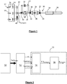
- the figure 1 schematically represents an exhaust line 10 of a heat engine 12 with its cylinder head 14.
- the gases exhaust out of the cylinders 16 by the exhaust valves 18 to enter the exhaust manifold 20.
- the gases then pass successively by a turbocharger 22 (for a supercharged engine) provided with a turbine 24 and a by -pass 26 ("waste gate"), a catalyst 28 with an upstream oxygen sensor 30 and a downstream probe 32, and silencers 34 and 36.
- the points to be thermally monitored, and the components that are to be protected thermally are mainly the upstream 40 of the turbocharger 22, the upstream 42 and the downstream 44 of the catalyst 28 with the probes 30 and 32, as well as the interior 46 of the catalyst 28 and the collector 20 (the monitored point of the collector is designated by 48 on the figure 1 ).
- the components are thermally protected by an adaptation of the control of the engine. The aim is that the temperatures at the monitored points do not exceed a critical value for which and beyond which the components (here the turbocharger and the catalyst with its probes) could be damaged.
- the invention consists in limiting the temperature of the exhaust gas at the engine outlet, by determining the enrichment necessary to not exceed the critical temperature of the component having reached this critical temperature, by inversion of the models. of the exhaust line.
- the figure 2 schematically illustrates the main steps of the process.
- the first two steps, corresponding to the modules 50 and 52, are generally known, the scope of the invention concerning the following two modules 54 and 56 surrounded by the rectangle 55.
- the module 50 makes it possible to estimate, using one or more model (s), the temperatures in the exhaust line according to various parameters such as the engine speed, the load, the feedrate. ignition and temperature outside the vehicle.
- Module 50 provides the Tech temperatures estimate gases and exhaust line walls, which are modeled separately or that can be measured by sensors.
- module 54 which develops a set target temperature T3 (also shown on the figure 1 ) which is the target temperature of the exhaust gas at the output of the heat engine and therefore at the outlet of the exhaust manifold 20.
- T3 also shown on the figure 1
- T3 the target temperature of the exhaust gas at the output of the heat engine and therefore at the outlet of the exhaust manifold 20.
- This set temperature T3 set is supplied to a module 56 which develops a ⁇ setpoint richness setpoint to be applied to the motor controller.
- Module 56 The detailed description of Module 56 will be made below using the Figures 4 and 5 .
- the temperature setpoint of the exhaust gas at the outlet of the engine, T3 setpoint thus represents the temperature of the exhaust gas to be met at the output of the engine to not exceed the maximum limit of critical temperature Tech [x] max of the element x identified.
- the difference between the two temperatures, T3 setpoint and Tech [x] max can be defined by a transfer function that takes into account the heat exchange in the exhaust line between the motor output and the element x.
- a transfer function is complex to model.
- figure 3 represents in detail an advantageous embodiment of the method relating to the development of the temperature setpoint of the exhaust gas at the output of the engine, T3 setpoint (module 54), to avoid the modeling of such a function of transfer.
- the prepositioning of the target temperature (illustrated by the rectangle 58) which provides, for the element x, a base temperature T3 (x) base (the temperature T3 is the temperature exhaust gas at the engine outlet, more precisely at the outlet of the exhaust manifold) and, on the other hand, a temperature regulation (rectangle 60) which provides a temperature correction term T3 (x) base .
- Prepositioning is used to initiate the control from a base temperature T3 (x) near basis of the temperature setpoint of exhaust gas at the output of the desired engine, which allows a faster regulation.
- maps 62 mapping by element x (only one element is monitored at a time, the element x).
- the index x of the element to be monitored is introduced by the input 64 of a selector 66 which selects the mapping of the element x.
- the mappings advantageously represent the air load of the engine 76 on the ordinate as a function of the engine speed 74 on the abscissa, with the temperature T3 as parameter.
- the mapping for element x gives the open loop base T3 (x) temperature which is refined using regulator 60.
- the regulator 60 is preferably of the proportional and integral type, although another type could be used (for example of the proportional, integral and derivative or proportional and derivative type or of a more complex type). It provides a corrective term for the T3 (x) base temperature.
- the controller consists of a proportional control 68 and an integral control 70. These two commands receive an information 72 which represents the temperature error of the component x to be protected, this error being equal to (Tech (x) max - Tech (x) estimate ).
- the two controls 68 and 70 also receive the engine speed 74 and the air load 76.
- the proportional control 68 delivers a correction term 78 which is proportional to the error 72 and the integral control 70 provides a corrective term 80 which represents the integration of the error as a function of time so as to converge the error signal.
- the correction terms 78 and 80 are added in an adder 82 which provides the corrective term 84.
- the latter is added with the temperature T3 (x) base provided by the prepositioning 58, in an adder 86.
- the regulated temperature (T3 (x) base + the corrective term) is supplied to an input 88 of a selector 90.
- the latter makes it possible to choose either the regulated temperature or a default temperature value T default (provided by a module 92 of unprotected temperature values ) when the protection is not active.
- the choice between these two entries is performed using a signal "component protection activation" applied to the input 94 of the module 90.
- the latter delivers the temperature of the setpoint T3 setpoint exhaust gas.
- the embodiment shown diagrammatically on the figure 3 can be replaced by an inversion of the models of the exhaust line.
- This variant makes it possible to reduce the calibration time as well as the number of calibrations.
- it has the drawbacks of being complex to implement and not to offer a degree of freedom in the calibration for controlling the behavior of the system.
- the mode of implementation illustrated by the figure 3 is then preferred.
- the Figures 4 and 5 schematically represent a mode of implementation of the development of a wealth directive (module 56 of the figure 2 ), the figure 4 schematically representing a direct model of exhaust gas temperature and wealth dependence and the figure 5 illustrating an inverse model for the determination of the richness allowing the protection of the components.
- the present invention allows a reduction of CO 2 emissions since it defines a just needed enrichment.
- it allows a good performance of limiting the temperature of the components of the exhaust line resulting in either a possibility of reducing the cost of the components by allowing operation at temperatures closer to the limits of the materials (dimensioning at most fair ), or by reducing CO 2 emissions by not anticipating activation of the function.
- the invention also allows a gain calibration cost: in fact, the direct models are already calibrated, no additional testing is necessary since it is sufficient to digitally invert the maps of direct models.
Landscapes
- Engineering & Computer Science (AREA)
- Chemical & Material Sciences (AREA)
- Combustion & Propulsion (AREA)
- Mechanical Engineering (AREA)
- General Engineering & Computer Science (AREA)
- Combined Controls Of Internal Combustion Engines (AREA)
- Exhaust Gas After Treatment (AREA)
- Exhaust Silencers (AREA)
Claims (9)
- Verfahren zum thermischen Schutz von Bauteilen der Abgasleitung einer Brennkraftmaschine, gemäß dem die Temperaturen der Abgase und der Wände der Abgasleitung bestimmt werden, und gemäß dem das Bauteil der Abgasleitung, das sein maximales Temperaturlimit erreicht hat, erfasst wird, und wobei man:- eine Sollwerttemperatur T3consigne der Abgase am Ausgang der Maschine bestimmt (54), um ihr maximales Temperaturlimit nicht zu überschreiten, und- man einen Reichhaltigkeitssollwert φconsigne ermittelt, der es erlaubt, die Sollwerttemperatur T3consigne der Abgase sicherzustellen,Verfahren dadurch gekennzeichnet, dass man zum Ermitteln des Reichhaltigkeitssollwerts φconsigne eine Temperatur T3estim der Abgase am Maschinenausgang für eine Reichhaltigkeit φ schätzt, wobei die Temperatur T3estim ausgehend von einer Temperatur T3estimφ=1 in Abhängigkeit von den verschiedenen Maschinenparametern (100) und für eine Reichhaltigkeit φ=100 bestimmt wird, wobei die Temperatur T3estimφ=1 mit Hilfe einer Korrekturfunktion f(Qech, φ) korrigiert wird, die durch Durchflusskartografie Qech der Abgase - Reichhaltigkeitssollwert φ bestimmt wird, wobei T3estim ausgehend von der folgenden Gleichung bestimmt wird:


- Verfahren nach Anspruch 1, dadurch gekennzeichnet, dass der Reichhaltigkeitssollwert φconsigne innerhalb des Limits der maximalen, von der Maschine akzeptablen Reichhaltigkeit bestimmt wird.
- Verfahren nach einem der vorhergehenden Ansprüche, dadurch gekennzeichnet, dass die Sollwerttemperatur T3consigne der Abgase am Maschinenausgang durch Vorpositionieren (58) der Sollwerttemperatur bestimmt wird, die eine Basistemperatur T3(x)base liefert, und durch Regulierung (60), die ein Korrekturglied der Basistemperatur liefert.
- Verfahren nach Anspruch 3, dadurch gekennzeichnet, dass die Vorpositionierung (58) eine Basissollwerttemperatur T3(x)base liefert, die mit Hilfe von Kartografien (62) in Abhängigkeit von dem Maschinenbetriebspunkt und dem zu schützenden Bauteil x bestimmt wird.
- Verfahren nach Anspruch 4, dadurch gekennzeichnet, dass die Kartografie Maschinen-Last-Drehzahl-Kartografien sind, die als Parameter die Temperatur am Maschinenausgang T3 haben.
- Verfahren nach einem der Ansprüche 3 bis 5, dadurch gekennzeichnet, dass die Regulierung (60) des proportionalen Typs (68) und integralen Typs (70) ist, die ein Korrekturglied (84) liefert.
- Verfahren nach einem der Ansprüche 3 bis 6, dadurch gekennzeichnet, dass das Korrekturglied (84) mit dem Vorpositionierungswert T3(x)base addiert wird, um die Temperatur T3consigne zu liefern.
- Verfahren nach einem der Ansprüche 1 und 2, dadurch gekennzeichnet, dass die Sollwerttemperatur T3consigne der Abgase am Maschinenausgang durch Umkehren der Modelle der Abgasleitung ermittelt wird.
- Verfahren nach einem der vorhergehenden Ansprüche, dadurch gekennzeichnet, dass die Maschinenparameter aus mindestens einem der folgenden Parameter bestehen: Betriebspunkt, Wassertemperatur, Verschlechterung des Zündvoreilwinkels und Positionierung der Einstellung der Nockenwellen.
Applications Claiming Priority (2)
| Application Number | Priority Date | Filing Date | Title |
|---|---|---|---|
| FR1250764A FR2986264B1 (fr) | 2012-01-26 | 2012-01-26 | Procede de protection thermique des composants de la ligne d'echappement d'un moteur thermique |
| PCT/FR2013/050072 WO2013110873A1 (fr) | 2012-01-26 | 2013-01-11 | Procédé de protection thermique des composants de la ligne d'échappement d'un moteur thermique |
Publications (2)
| Publication Number | Publication Date |
|---|---|
| EP2807353A1 EP2807353A1 (de) | 2014-12-03 |
| EP2807353B1 true EP2807353B1 (de) | 2017-03-08 |
Family
ID=47714392
Family Applications (1)
| Application Number | Title | Priority Date | Filing Date |
|---|---|---|---|
| EP13704153.9A Active EP2807353B1 (de) | 2012-01-26 | 2013-01-11 | Verfahren zum thermischen schutz der abgasleitung eines verbrennungsmotors |
Country Status (5)
| Country | Link |
|---|---|
| EP (1) | EP2807353B1 (de) |
| CN (1) | CN104246160B (de) |
| BR (1) | BR112014017533B1 (de) |
| FR (1) | FR2986264B1 (de) |
| WO (1) | WO2013110873A1 (de) |
Citations (1)
| Publication number | Priority date | Publication date | Assignee | Title |
|---|---|---|---|---|
| EP1329627A2 (de) * | 2002-01-16 | 2003-07-23 | Bayerische Motoren Werke Aktiengesellschaft | Verfahren und Vorrichtung zum Steuern einer Bauteilschutzfunktion |
Family Cites Families (10)
| Publication number | Priority date | Publication date | Assignee | Title |
|---|---|---|---|---|
| US3696618A (en) | 1971-04-19 | 1972-10-10 | Universal Oil Prod Co | Control system for an engine system |
| JPH0460106A (ja) | 1990-06-29 | 1992-02-26 | Mazda Motor Corp | エンジンの制御装置 |
| JP3189381B2 (ja) | 1992-04-30 | 2001-07-16 | スズキ株式会社 | 内燃機関の空燃比制御装置 |
| DE10043687A1 (de) * | 2000-09-04 | 2002-03-14 | Bosch Gmbh Robert | Koordination verschiedener Anforderungen an die Abgastemperatur und entsprechende Heiz-oder Kühl-Maßnahmen |
| US6691507B1 (en) * | 2000-10-16 | 2004-02-17 | Ford Global Technologies, Llc | Closed-loop temperature control for an emission control device |
| DE10147619A1 (de) * | 2001-09-27 | 2003-07-10 | Volkswagen Ag | Verfahren zum Schutz von Abgasreinigungssystemen von Brennkraftmaschinen vor thermischer Überbelastung |
| US20040123588A1 (en) * | 2002-12-30 | 2004-07-01 | Stanglmaier Rudolf H. | Method for controlling exhaust gas temperature and space velocity during regeneration to protect temperature sensitive diesel engine components and aftertreatment devices |
| US7441403B2 (en) * | 2004-12-20 | 2008-10-28 | Detroit Diesel Corporation | Method and system for determining temperature set points in systems having particulate filters with regeneration capabilities |
| FR2880066B1 (fr) * | 2004-12-24 | 2007-03-16 | Renault Sas | Procede et systeme de commande d'un moteur diesel a richesse superieure a 1 |
| JP5609349B2 (ja) * | 2010-07-13 | 2014-10-22 | トヨタ自動車株式会社 | 触媒の過熱防止装置 |
-
2012
- 2012-01-26 FR FR1250764A patent/FR2986264B1/fr not_active Expired - Fee Related
-
2013
- 2013-01-11 BR BR112014017533-0A patent/BR112014017533B1/pt not_active IP Right Cessation
- 2013-01-11 CN CN201380006875.6A patent/CN104246160B/zh not_active Expired - Fee Related
- 2013-01-11 EP EP13704153.9A patent/EP2807353B1/de active Active
- 2013-01-11 WO PCT/FR2013/050072 patent/WO2013110873A1/fr not_active Ceased
Patent Citations (1)
| Publication number | Priority date | Publication date | Assignee | Title |
|---|---|---|---|---|
| EP1329627A2 (de) * | 2002-01-16 | 2003-07-23 | Bayerische Motoren Werke Aktiengesellschaft | Verfahren und Vorrichtung zum Steuern einer Bauteilschutzfunktion |
Also Published As
| Publication number | Publication date |
|---|---|
| FR2986264A1 (fr) | 2013-08-02 |
| WO2013110873A1 (fr) | 2013-08-01 |
| BR112014017533B1 (pt) | 2021-05-04 |
| CN104246160B (zh) | 2017-02-22 |
| BR112014017533A8 (pt) | 2017-07-04 |
| EP2807353A1 (de) | 2014-12-03 |
| BR112014017533A2 (pt) | 2017-06-13 |
| CN104246160A (zh) | 2014-12-24 |
| FR2986264B1 (fr) | 2014-01-10 |
Similar Documents
| Publication | Publication Date | Title |
|---|---|---|
| EP2007976A1 (de) | Verfahren und vorrichtung zur überwachung der regeneration eines verunreinigungsentfernungssystems | |
| FR2838164A1 (fr) | Procede et dispositif de commande d'un moteur | |
| FR2852631A1 (fr) | Procede et dispositif de commande d'un moteur thermique | |
| FR3065990A1 (fr) | Procede de reactualisation d’une dynamique d’adaptation d’une valeur de richesse a une consigne dans un moteur | |
| WO2019110882A1 (fr) | Système et procédé de commande d'un moteur à combustion interne muni d'un système de post traitement des gaz d'échappement de type à catalyse sélective | |
| EP0954689B1 (de) | Steuervorrichtung für eine brennkraftmaschine mit gesteuerter zündung und direkter einspritzung | |
| FR2915237A1 (fr) | Systeme et procede de commande d'un turbocompresseur de suralimentation pour moteur a combustion interne | |
| FR2874237A1 (fr) | Procede et dispositif de gestion d'un moteur a combustion interne | |
| EP1950396A1 (de) | Verfahren und System zur Temperaturbegrenzung am Auslass eines Dieselmotors | |
| EP2430298B1 (de) | Schätzung der nox-konzentration (stickoxide) in einer brennkraftmaschine | |
| FR2955356A1 (fr) | Procede et dispositif de gestion d'un moteur thermique | |
| EP0264332B1 (de) | Verfahren zum Korrigieren der Anreicherung eines Kraftstoffluftgemisches in einem elektronisch geregelten Einspritzverbrennungsmotor | |
| FR3057022A1 (fr) | Procede de surveillance d'un catalyseur associe a un moteur a allumage commande | |
| EP2307675A1 (de) | Verfahren zur abstimmung der temperatureinstellung bei einem partikelfilter | |
| WO2013110873A1 (fr) | Procédé de protection thermique des composants de la ligne d'échappement d'un moteur thermique | |
| FR2931876A1 (fr) | Dispositif et procede de regulation des phases de regeneration d'un filtre a particules pour moteur a combustion. | |
| JP5241694B2 (ja) | エンジン始動時のシリンダ流入空気量補正方法、及びその方法を備えた燃料制御装置 | |
| EP2761153B1 (de) | Steuerung der kraftstoffeinspritzung beim start eines verbrennungsmotors | |
| FR2916805A1 (fr) | Dispositif et procede d'estimation d'une quantite d'alcool contenue dans le carburant d'un moteur. | |
| EP1760295B1 (de) | Regelvorrichtung für eine Diesel-Brennkraftmaschine mit Abgasrückführung | |
| EP0948711B1 (de) | Verfahren zum regeln des krafstoff/luft -verhaltnisses einer brennkraftmaschine mit adaptiverkrafstoff/luft -verhaltnis-sollwert | |
| FR2871195A1 (fr) | Procede et dispositif de gestion d'un moteur a combustion interne | |
| EP3004608B1 (de) | Verfahren zur messung des schadstoffausstosses eines verbrennungsmotors und verfahren zur steuerung des motors | |
| EP1693559B1 (de) | Steuerungssystem zum Betreiben eines Dieselmotors mit Abgasrückführung | |
| EP1916404A1 (de) | Verfahren zur Schätzung der charakteristischen Parameter einer Wärmekraftmaschine und zur Kontrolle der Wärmeströme, die Teile dieses Motors erreichen |
Legal Events
| Date | Code | Title | Description |
|---|---|---|---|
| PUAI | Public reference made under article 153(3) epc to a published international application that has entered the european phase |
Free format text: ORIGINAL CODE: 0009012 |
|
| 17P | Request for examination filed |
Effective date: 20140620 |
|
| AK | Designated contracting states |
Kind code of ref document: A1 Designated state(s): AL AT BE BG CH CY CZ DE DK EE ES FI FR GB GR HR HU IE IS IT LI LT LU LV MC MK MT NL NO PL PT RO RS SE SI SK SM TR |
|
| DAX | Request for extension of the european patent (deleted) | ||
| RIN1 | Information on inventor provided before grant (corrected) |
Inventor name: KRETZAS, EFSTRATIOS Inventor name: ALLEGRE, GUILLAUME |
|
| RIN1 | Information on inventor provided before grant (corrected) |
Inventor name: KRETZAS, EFSTRATIOS Inventor name: ALLEGRE, GUILLAUME |
|
| RAP1 | Party data changed (applicant data changed or rights of an application transferred) |
Owner name: PEUGEOT CITROEN AUTOMOBILES SA |
|
| 17Q | First examination report despatched |
Effective date: 20160115 |
|
| RIC1 | Information provided on ipc code assigned before grant |
Ipc: F01N 11/00 20060101AFI20160805BHEP |
|
| GRAP | Despatch of communication of intention to grant a patent |
Free format text: ORIGINAL CODE: EPIDOSNIGR1 |
|
| INTG | Intention to grant announced |
Effective date: 20160929 |
|
| GRAS | Grant fee paid |
Free format text: ORIGINAL CODE: EPIDOSNIGR3 |
|
| GRAA | (expected) grant |
Free format text: ORIGINAL CODE: 0009210 |
|
| AK | Designated contracting states |
Kind code of ref document: B1 Designated state(s): AL AT BE BG CH CY CZ DE DK EE ES FI FR GB GR HR HU IE IS IT LI LT LU LV MC MK MT NL NO PL PT RO RS SE SI SK SM TR |
|
| REG | Reference to a national code |
Ref country code: GB Ref legal event code: FG4D Free format text: NOT ENGLISH |
|
| REG | Reference to a national code |
Ref country code: CH Ref legal event code: EP Ref country code: AT Ref legal event code: REF Ref document number: 873734 Country of ref document: AT Kind code of ref document: T Effective date: 20170315 |
|
| REG | Reference to a national code |
Ref country code: IE Ref legal event code: FG4D Free format text: LANGUAGE OF EP DOCUMENT: FRENCH |
|
| REG | Reference to a national code |
Ref country code: DE Ref legal event code: R096 Ref document number: 602013018247 Country of ref document: DE |
|
| REG | Reference to a national code |
Ref country code: DE Ref legal event code: R084 Ref document number: 602013018247 Country of ref document: DE |
|
| REG | Reference to a national code |
Ref country code: LT Ref legal event code: MG4D |
|
| REG | Reference to a national code |
Ref country code: NL Ref legal event code: MP Effective date: 20170308 |
|
| REG | Reference to a national code |
Ref country code: GB Ref legal event code: 746 Effective date: 20170630 |
|
| PG25 | Lapsed in a contracting state [announced via postgrant information from national office to epo] |
Ref country code: FI Free format text: LAPSE BECAUSE OF FAILURE TO SUBMIT A TRANSLATION OF THE DESCRIPTION OR TO PAY THE FEE WITHIN THE PRESCRIBED TIME-LIMIT Effective date: 20170308 Ref country code: LT Free format text: LAPSE BECAUSE OF FAILURE TO SUBMIT A TRANSLATION OF THE DESCRIPTION OR TO PAY THE FEE WITHIN THE PRESCRIBED TIME-LIMIT Effective date: 20170308 Ref country code: NO Free format text: LAPSE BECAUSE OF FAILURE TO SUBMIT A TRANSLATION OF THE DESCRIPTION OR TO PAY THE FEE WITHIN THE PRESCRIBED TIME-LIMIT Effective date: 20170608 Ref country code: HR Free format text: LAPSE BECAUSE OF FAILURE TO SUBMIT A TRANSLATION OF THE DESCRIPTION OR TO PAY THE FEE WITHIN THE PRESCRIBED TIME-LIMIT Effective date: 20170308 Ref country code: GR Free format text: LAPSE BECAUSE OF FAILURE TO SUBMIT A TRANSLATION OF THE DESCRIPTION OR TO PAY THE FEE WITHIN THE PRESCRIBED TIME-LIMIT Effective date: 20170609 |
|
| REG | Reference to a national code |
Ref country code: AT Ref legal event code: MK05 Ref document number: 873734 Country of ref document: AT Kind code of ref document: T Effective date: 20170308 |
|
| RAP2 | Party data changed (patent owner data changed or rights of a patent transferred) |
Owner name: PSA AUTOMOBILES SA |
|
| PG25 | Lapsed in a contracting state [announced via postgrant information from national office to epo] |
Ref country code: RS Free format text: LAPSE BECAUSE OF FAILURE TO SUBMIT A TRANSLATION OF THE DESCRIPTION OR TO PAY THE FEE WITHIN THE PRESCRIBED TIME-LIMIT Effective date: 20170308 Ref country code: SE Free format text: LAPSE BECAUSE OF FAILURE TO SUBMIT A TRANSLATION OF THE DESCRIPTION OR TO PAY THE FEE WITHIN THE PRESCRIBED TIME-LIMIT Effective date: 20170308 Ref country code: LV Free format text: LAPSE BECAUSE OF FAILURE TO SUBMIT A TRANSLATION OF THE DESCRIPTION OR TO PAY THE FEE WITHIN THE PRESCRIBED TIME-LIMIT Effective date: 20170308 Ref country code: BG Free format text: LAPSE BECAUSE OF FAILURE TO SUBMIT A TRANSLATION OF THE DESCRIPTION OR TO PAY THE FEE WITHIN THE PRESCRIBED TIME-LIMIT Effective date: 20170608 Ref country code: ES Free format text: LAPSE BECAUSE OF FAILURE TO SUBMIT A TRANSLATION OF THE DESCRIPTION OR TO PAY THE FEE WITHIN THE PRESCRIBED TIME-LIMIT Effective date: 20170308 |
|
| PG25 | Lapsed in a contracting state [announced via postgrant information from national office to epo] |
Ref country code: NL Free format text: LAPSE BECAUSE OF FAILURE TO SUBMIT A TRANSLATION OF THE DESCRIPTION OR TO PAY THE FEE WITHIN THE PRESCRIBED TIME-LIMIT Effective date: 20170308 |
|
| PG25 | Lapsed in a contracting state [announced via postgrant information from national office to epo] |
Ref country code: AT Free format text: LAPSE BECAUSE OF FAILURE TO SUBMIT A TRANSLATION OF THE DESCRIPTION OR TO PAY THE FEE WITHIN THE PRESCRIBED TIME-LIMIT Effective date: 20170308 Ref country code: CZ Free format text: LAPSE BECAUSE OF FAILURE TO SUBMIT A TRANSLATION OF THE DESCRIPTION OR TO PAY THE FEE WITHIN THE PRESCRIBED TIME-LIMIT Effective date: 20170308 Ref country code: EE Free format text: LAPSE BECAUSE OF FAILURE TO SUBMIT A TRANSLATION OF THE DESCRIPTION OR TO PAY THE FEE WITHIN THE PRESCRIBED TIME-LIMIT Effective date: 20170308 Ref country code: RO Free format text: LAPSE BECAUSE OF FAILURE TO SUBMIT A TRANSLATION OF THE DESCRIPTION OR TO PAY THE FEE WITHIN THE PRESCRIBED TIME-LIMIT Effective date: 20170308 Ref country code: SK Free format text: LAPSE BECAUSE OF FAILURE TO SUBMIT A TRANSLATION OF THE DESCRIPTION OR TO PAY THE FEE WITHIN THE PRESCRIBED TIME-LIMIT Effective date: 20170308 |
|
| PG25 | Lapsed in a contracting state [announced via postgrant information from national office to epo] |
Ref country code: SM Free format text: LAPSE BECAUSE OF FAILURE TO SUBMIT A TRANSLATION OF THE DESCRIPTION OR TO PAY THE FEE WITHIN THE PRESCRIBED TIME-LIMIT Effective date: 20170308 Ref country code: PT Free format text: LAPSE BECAUSE OF FAILURE TO SUBMIT A TRANSLATION OF THE DESCRIPTION OR TO PAY THE FEE WITHIN THE PRESCRIBED TIME-LIMIT Effective date: 20170710 Ref country code: IS Free format text: LAPSE BECAUSE OF FAILURE TO SUBMIT A TRANSLATION OF THE DESCRIPTION OR TO PAY THE FEE WITHIN THE PRESCRIBED TIME-LIMIT Effective date: 20170708 Ref country code: PL Free format text: LAPSE BECAUSE OF FAILURE TO SUBMIT A TRANSLATION OF THE DESCRIPTION OR TO PAY THE FEE WITHIN THE PRESCRIBED TIME-LIMIT Effective date: 20170308 |
|
| REG | Reference to a national code |
Ref country code: DE Ref legal event code: R097 Ref document number: 602013018247 Country of ref document: DE |
|
| REG | Reference to a national code |
Ref country code: FR Ref legal event code: PLFP Year of fee payment: 6 |
|
| PLBE | No opposition filed within time limit |
Free format text: ORIGINAL CODE: 0009261 |
|
| STAA | Information on the status of an ep patent application or granted ep patent |
Free format text: STATUS: NO OPPOSITION FILED WITHIN TIME LIMIT |
|
| PG25 | Lapsed in a contracting state [announced via postgrant information from national office to epo] |
Ref country code: DK Free format text: LAPSE BECAUSE OF FAILURE TO SUBMIT A TRANSLATION OF THE DESCRIPTION OR TO PAY THE FEE WITHIN THE PRESCRIBED TIME-LIMIT Effective date: 20170308 |
|
| 26N | No opposition filed |
Effective date: 20171211 |
|
| PG25 | Lapsed in a contracting state [announced via postgrant information from national office to epo] |
Ref country code: IT Free format text: LAPSE BECAUSE OF FAILURE TO SUBMIT A TRANSLATION OF THE DESCRIPTION OR TO PAY THE FEE WITHIN THE PRESCRIBED TIME-LIMIT Effective date: 20170308 Ref country code: SI Free format text: LAPSE BECAUSE OF FAILURE TO SUBMIT A TRANSLATION OF THE DESCRIPTION OR TO PAY THE FEE WITHIN THE PRESCRIBED TIME-LIMIT Effective date: 20170308 |
|
| REG | Reference to a national code |
Ref country code: FR Ref legal event code: CA Effective date: 20180312 Ref country code: FR Ref legal event code: CD Owner name: PEUGEOT CITROEN AUTOMOBILES SA, FR Effective date: 20180312 |
|
| REG | Reference to a national code |
Ref country code: CH Ref legal event code: PL |
|
| PG25 | Lapsed in a contracting state [announced via postgrant information from national office to epo] |
Ref country code: MT Free format text: LAPSE BECAUSE OF FAILURE TO SUBMIT A TRANSLATION OF THE DESCRIPTION OR TO PAY THE FEE WITHIN THE PRESCRIBED TIME-LIMIT Effective date: 20170308 |
|
| PG25 | Lapsed in a contracting state [announced via postgrant information from national office to epo] |
Ref country code: LU Free format text: LAPSE BECAUSE OF NON-PAYMENT OF DUE FEES Effective date: 20180111 |
|
| REG | Reference to a national code |
Ref country code: IE Ref legal event code: MM4A |
|
| REG | Reference to a national code |
Ref country code: BE Ref legal event code: MM Effective date: 20180131 |
|
| PG25 | Lapsed in a contracting state [announced via postgrant information from national office to epo] |
Ref country code: BE Free format text: LAPSE BECAUSE OF NON-PAYMENT OF DUE FEES Effective date: 20180131 Ref country code: LI Free format text: LAPSE BECAUSE OF NON-PAYMENT OF DUE FEES Effective date: 20180131 Ref country code: CH Free format text: LAPSE BECAUSE OF NON-PAYMENT OF DUE FEES Effective date: 20180131 |
|
| PG25 | Lapsed in a contracting state [announced via postgrant information from national office to epo] |
Ref country code: IE Free format text: LAPSE BECAUSE OF NON-PAYMENT OF DUE FEES Effective date: 20180111 |
|
| PG25 | Lapsed in a contracting state [announced via postgrant information from national office to epo] |
Ref country code: MC Free format text: LAPSE BECAUSE OF FAILURE TO SUBMIT A TRANSLATION OF THE DESCRIPTION OR TO PAY THE FEE WITHIN THE PRESCRIBED TIME-LIMIT Effective date: 20170308 |
|
| PG25 | Lapsed in a contracting state [announced via postgrant information from national office to epo] |
Ref country code: TR Free format text: LAPSE BECAUSE OF FAILURE TO SUBMIT A TRANSLATION OF THE DESCRIPTION OR TO PAY THE FEE WITHIN THE PRESCRIBED TIME-LIMIT Effective date: 20170308 |
|
| PG25 | Lapsed in a contracting state [announced via postgrant information from national office to epo] |
Ref country code: HU Free format text: LAPSE BECAUSE OF FAILURE TO SUBMIT A TRANSLATION OF THE DESCRIPTION OR TO PAY THE FEE WITHIN THE PRESCRIBED TIME-LIMIT; INVALID AB INITIO Effective date: 20130111 |
|
| PG25 | Lapsed in a contracting state [announced via postgrant information from national office to epo] |
Ref country code: CY Free format text: LAPSE BECAUSE OF FAILURE TO SUBMIT A TRANSLATION OF THE DESCRIPTION OR TO PAY THE FEE WITHIN THE PRESCRIBED TIME-LIMIT Effective date: 20170308 Ref country code: MK Free format text: LAPSE BECAUSE OF NON-PAYMENT OF DUE FEES Effective date: 20170308 |
|
| PG25 | Lapsed in a contracting state [announced via postgrant information from national office to epo] |
Ref country code: AL Free format text: LAPSE BECAUSE OF FAILURE TO SUBMIT A TRANSLATION OF THE DESCRIPTION OR TO PAY THE FEE WITHIN THE PRESCRIBED TIME-LIMIT Effective date: 20170308 |
|
| PGFP | Annual fee paid to national office [announced via postgrant information from national office to epo] |
Ref country code: GB Payment date: 20241224 Year of fee payment: 13 |
|
| PGFP | Annual fee paid to national office [announced via postgrant information from national office to epo] |
Ref country code: DE Payment date: 20241218 Year of fee payment: 13 |
|
| PGFP | Annual fee paid to national office [announced via postgrant information from national office to epo] |
Ref country code: FR Payment date: 20251218 Year of fee payment: 14 |