EP1916404A1 - Verfahren zur Schätzung der charakteristischen Parameter einer Wärmekraftmaschine und zur Kontrolle der Wärmeströme, die Teile dieses Motors erreichen - Google Patents
Verfahren zur Schätzung der charakteristischen Parameter einer Wärmekraftmaschine und zur Kontrolle der Wärmeströme, die Teile dieses Motors erreichen Download PDFInfo
- Publication number
- EP1916404A1 EP1916404A1 EP07301462A EP07301462A EP1916404A1 EP 1916404 A1 EP1916404 A1 EP 1916404A1 EP 07301462 A EP07301462 A EP 07301462A EP 07301462 A EP07301462 A EP 07301462A EP 1916404 A1 EP1916404 A1 EP 1916404A1
- Authority
- EP
- European Patent Office
- Prior art keywords
- engine
- fuel
- heat
- combustion
- heat engine
- Prior art date
- Legal status (The legal status is an assumption and is not a legal conclusion. Google has not performed a legal analysis and makes no representation as to the accuracy of the status listed.)
- Withdrawn
Links
- 238000000034 method Methods 0.000 title claims abstract description 49
- 230000004907 flux Effects 0.000 title claims abstract description 35
- 239000000446 fuel Substances 0.000 claims abstract description 78
- 238000002485 combustion reaction Methods 0.000 claims abstract description 70
- 239000000203 mixture Substances 0.000 claims abstract description 29
- 238000004364 calculation method Methods 0.000 claims description 29
- 238000002347 injection Methods 0.000 claims description 23
- 239000007924 injection Substances 0.000 claims description 23
- 239000007789 gas Substances 0.000 claims description 20
- 230000006870 function Effects 0.000 claims description 17
- 230000008569 process Effects 0.000 claims description 17
- 238000013507 mapping Methods 0.000 claims description 11
- 238000012937 correction Methods 0.000 claims description 8
- 238000005259 measurement Methods 0.000 claims description 8
- 230000010354 integration Effects 0.000 claims description 5
- 238000013461 design Methods 0.000 claims description 4
- 238000010438 heat treatment Methods 0.000 claims description 3
- 238000005255 carburizing Methods 0.000 claims description 2
- 238000004064 recycling Methods 0.000 claims description 2
- 238000012360 testing method Methods 0.000 claims description 2
- 238000011161 development Methods 0.000 description 9
- 230000001276 controlling effect Effects 0.000 description 7
- 239000000567 combustion gas Substances 0.000 description 5
- 230000009471 action Effects 0.000 description 4
- 230000006835 compression Effects 0.000 description 4
- 238000007906 compression Methods 0.000 description 4
- 239000006185 dispersion Substances 0.000 description 3
- 235000021183 entrée Nutrition 0.000 description 3
- 230000006978 adaptation Effects 0.000 description 2
- 238000010586 diagram Methods 0.000 description 2
- 230000020169 heat generation Effects 0.000 description 2
- 230000007257 malfunction Effects 0.000 description 2
- 230000006399 behavior Effects 0.000 description 1
- 238000009530 blood pressure measurement Methods 0.000 description 1
- 230000008859 change Effects 0.000 description 1
- 238000009838 combustion analysis Methods 0.000 description 1
- 238000011217 control strategy Methods 0.000 description 1
- 230000008878 coupling Effects 0.000 description 1
- 238000010168 coupling process Methods 0.000 description 1
- 238000005859 coupling reaction Methods 0.000 description 1
- 230000001186 cumulative effect Effects 0.000 description 1
- 230000006378 damage Effects 0.000 description 1
- 238000013500 data storage Methods 0.000 description 1
- 230000003111 delayed effect Effects 0.000 description 1
- 238000005516 engineering process Methods 0.000 description 1
- 239000003344 environmental pollutant Substances 0.000 description 1
- 238000012986 modification Methods 0.000 description 1
- 230000004048 modification Effects 0.000 description 1
- 239000003607 modifier Substances 0.000 description 1
- 210000000056 organ Anatomy 0.000 description 1
- 231100000719 pollutant Toxicity 0.000 description 1
- 230000001105 regulatory effect Effects 0.000 description 1
- 230000035945 sensitivity Effects 0.000 description 1
- 239000002341 toxic gas Substances 0.000 description 1
- 238000012546 transfer Methods 0.000 description 1
- XLYOFNOQVPJJNP-UHFFFAOYSA-N water Substances O XLYOFNOQVPJJNP-UHFFFAOYSA-N 0.000 description 1
Images

Classifications
-
- F—MECHANICAL ENGINEERING; LIGHTING; HEATING; WEAPONS; BLASTING
- F02—COMBUSTION ENGINES; HOT-GAS OR COMBUSTION-PRODUCT ENGINE PLANTS
- F02D—CONTROLLING COMBUSTION ENGINES
- F02D41/00—Electrical control of supply of combustible mixture or its constituents
- F02D41/02—Circuit arrangements for generating control signals
- F02D41/14—Introducing closed-loop corrections
- F02D41/1401—Introducing closed-loop corrections characterised by the control or regulation method
-
- F—MECHANICAL ENGINEERING; LIGHTING; HEATING; WEAPONS; BLASTING
- F02—COMBUSTION ENGINES; HOT-GAS OR COMBUSTION-PRODUCT ENGINE PLANTS
- F02D—CONTROLLING COMBUSTION ENGINES
- F02D35/00—Controlling engines, dependent on conditions exterior or interior to engines, not otherwise provided for
- F02D35/02—Controlling engines, dependent on conditions exterior or interior to engines, not otherwise provided for on interior conditions
- F02D35/023—Controlling engines, dependent on conditions exterior or interior to engines, not otherwise provided for on interior conditions by determining the cylinder pressure
-
- F—MECHANICAL ENGINEERING; LIGHTING; HEATING; WEAPONS; BLASTING
- F02—COMBUSTION ENGINES; HOT-GAS OR COMBUSTION-PRODUCT ENGINE PLANTS
- F02D—CONTROLLING COMBUSTION ENGINES
- F02D35/00—Controlling engines, dependent on conditions exterior or interior to engines, not otherwise provided for
- F02D35/02—Controlling engines, dependent on conditions exterior or interior to engines, not otherwise provided for on interior conditions
- F02D35/028—Controlling engines, dependent on conditions exterior or interior to engines, not otherwise provided for on interior conditions by determining the combustion timing or phasing
-
- F—MECHANICAL ENGINEERING; LIGHTING; HEATING; WEAPONS; BLASTING
- F02—COMBUSTION ENGINES; HOT-GAS OR COMBUSTION-PRODUCT ENGINE PLANTS
- F02D—CONTROLLING COMBUSTION ENGINES
- F02D41/00—Electrical control of supply of combustible mixture or its constituents
- F02D41/02—Circuit arrangements for generating control signals
- F02D41/14—Introducing closed-loop corrections
- F02D41/1401—Introducing closed-loop corrections characterised by the control or regulation method
- F02D2041/1433—Introducing closed-loop corrections characterised by the control or regulation method using a model or simulation of the system
-
- F—MECHANICAL ENGINEERING; LIGHTING; HEATING; WEAPONS; BLASTING
- F02—COMBUSTION ENGINES; HOT-GAS OR COMBUSTION-PRODUCT ENGINE PLANTS
- F02D—CONTROLLING COMBUSTION ENGINES
- F02D2200/00—Input parameters for engine control
- F02D2200/02—Input parameters for engine control the parameters being related to the engine
- F02D2200/04—Engine intake system parameters
- F02D2200/0402—Engine intake system parameters the parameter being determined by using a model of the engine intake or its components
-
- F—MECHANICAL ENGINEERING; LIGHTING; HEATING; WEAPONS; BLASTING
- F02—COMBUSTION ENGINES; HOT-GAS OR COMBUSTION-PRODUCT ENGINE PLANTS
- F02D—CONTROLLING COMBUSTION ENGINES
- F02D2200/00—Input parameters for engine control
- F02D2200/02—Input parameters for engine control the parameters being related to the engine
- F02D2200/06—Fuel or fuel supply system parameters
- F02D2200/0614—Actual fuel mass or fuel injection amount
- F02D2200/0616—Actual fuel mass or fuel injection amount determined by estimation
-
- F—MECHANICAL ENGINEERING; LIGHTING; HEATING; WEAPONS; BLASTING
- F02—COMBUSTION ENGINES; HOT-GAS OR COMBUSTION-PRODUCT ENGINE PLANTS
- F02D—CONTROLLING COMBUSTION ENGINES
- F02D41/00—Electrical control of supply of combustible mixture or its constituents
- F02D41/0025—Controlling engines characterised by use of non-liquid fuels, pluralities of fuels, or non-fuel substances added to the combustible mixtures
- F02D41/0047—Controlling exhaust gas recirculation [EGR]
-
- F—MECHANICAL ENGINEERING; LIGHTING; HEATING; WEAPONS; BLASTING
- F02—COMBUSTION ENGINES; HOT-GAS OR COMBUSTION-PRODUCT ENGINE PLANTS
- F02D—CONTROLLING COMBUSTION ENGINES
- F02D41/00—Electrical control of supply of combustible mixture or its constituents
- F02D41/30—Controlling fuel injection
- F02D41/38—Controlling fuel injection of the high pressure type
- F02D41/40—Controlling fuel injection of the high pressure type with means for controlling injection timing or duration
- F02D41/402—Multiple injections
Definitions
- the invention relates to a method for estimating the parameters characterizing the operation of a heat engine and controlling heat flows applied to components of this engine.
- the method according to the invention makes it possible to directly control, in a closed loop and in real time, the thermal flux levels applied to these motor components.
- engine applies equally to all types of combustion engines, whether of gasoline or diesel type.
- engine will be used.
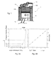
- Figure 1 at the end of the present description illustrates very schematically an example of configuration of a cylinder block 1 of a heat engine.
- the main components comprise a cylinder proper 11, a cylinder head 10 and a piston 12 in linear movement back and forth within the walls of the cylinder 11.
- the space between the upper wall of the piston 12 and the lower wall of the cylinder head 10 defines the combustion chamber 13, a place of intense heating due to the combustion of the gas mixture injected into this chamber. This results in significant heat transfer to the walls of the cylinder head 10, the cylinder 11 and to the piston 12.
- the four-stroke engines are provided with "water jackets", 100 and 110 respectively, the water circulating in enclosures created in the walls of the cylinder head 10 and the cylinder 11.
- T piston wall , T cylinder wall , T cylinder wall represent the respective temperatures (in ° C) of the walls of these components and S piston , S cylinder head , S cylinder , their surfaces (in m 2 ) exposure to the flow thermal.
- the combustion gas is the temperature of the gases (in ° C) during combustion, that is to say the temperature prevailing in the combustion chamber 13.
- the coefficient K is obtained by empirical correlations generally used during combustion analyzes for the calculation of heat flux.
- the correlation most often used is the so-called "Woschni” correlation which makes it possible to fix this coefficient K.
- heat fluxes are generally calculated using combustion analysis software which determines the temperatures of the combustion gases as well as the wall temperatures as functions of predetermined motor parameters (air mass, fuel mass, etc.)
- the parameters influencing the thermal flows are multiple.
- This relationship can be linear (which is usually true at full load), or higher.
- the absolute flows can be calculated in a given repository by using a combustion analysis tool, and the parameters of the previous linear relation identified.
- the different input parameters above can be system data (calculator instructions for the fuel mass, the injection advance, etc.).
- the object of the invention is to provide a method of estimating determined physical parameters, characteristic of the operation of a heat engine, and of controlling the thermal flows to which the components of this heat engine are subjected, aiming at overcoming the disadvantages of the processes and devices of the known art, some of which have just been recalled
- the estimation of determined physical parameters associated with an engine thermal is performed in real time, in particular with regard to the fuel flow, the air flow, the combustion phase, etc., as a function of the cylinder pressure, the associated thermal flows as a function of identified constants being calculated during the development of this engine, that is to say during a preliminary or initial phase, for example experimentally.
- the temperature of the injected air + EGR mixture can be measured or estimated by a predetermined specific model. If the "measurement” option is selected, this measurement can be done in the intake manifold for example, taking into account the "EGR" mentioned above.
- the estimation of the parameters and the flow control having the characteristics recalled above can be obtained by measuring the pressure prevailing in all or some of the cylinders, and by adopting a control strategy, using this cylinder pressure parameter, which will be specified. and detailed below.
- Such a measurement can be made simply by using one or more standard pressure sensor implanted in one or more rolls. Current motors of such sensors are already present, and the pressure measurement necessary to perform the control step according to the invention does not entail a significant additional cost and complexity.
- the invention thus has many advantages, in particular the method of the invention makes it possible to reduce the development margins during the development of the engines with respect to the thermal flows, and to control the flow levels during critical life situations. for the motor components. It allows a good behavior over time of these components.
- FIG. 2 very schematically illustrates such a configuration. Only the essential organs necessary for a good understanding of the invention have been represented.
- the motor 3 includes an engine block 30 itself comprising, in the example of Figure 2, four cylinders 1a to 1d, similar to the cylinder 1 already described with reference to Figure 1.
- an engine inlet block 30 fresh air is fed to the cylinders, 1a to 1d, via an intake duct 310, to an inlet manifold 31 and the individual conduits 311. at the output of the engine block 30, the exhaust gas is expelled by an exhaust line 300.
- a stitching member of the EGR consists of a valve 33 for diverting to the inlet distributor 31 via a conduit 330, a variable percentage of the exhaust gas. It therefore turns out that, in fact, the intake distributor 31 delivers an air / exhaust mixture at the inlet of the engine 3by the intake duct 310.
- one or more pressure sensors 34 for measuring the pressure in the combustion chambers of the cylinders 1 a to 1 d, at least one sensor being necessary in the specific context of the invention .
- This or these sensors 34 may be integrated in the cylinder head or in the glow plugs.
- the sensors 34 measure the pressure in the combustion chamber of all or part of the cylinders 1a through 1d.
- the output signals of sensors 34 are transmitted to an electronic control unit or "ECU” (for "Electronic Control Unit” according to the English terminology commonly used).
- a temperature sensor 35 is also provided on the intake distributor 31. The measured signals are also transmitted to the computer 32.
- the motor 3 also comprises a body 40 comprising a common supply rail (not shown) adapted to feed the engine cylinders, 1a to 1d, in multiple injections of fuel such as a pilot injection followed by a main injection.
- a common supply rail not shown
- the output signals of these devices are transmitted to the computer 32.
- the computer 32 According to these signals and other standard signals, the computer 32 generates control signals, in a conventional manner per se, and transmits control signals making it possible to drive specific members of the motor 3 (injectors not shown, valve 33, member 40, etc.), especially those necessary for carrying out the process of the invention.
- the computer 32 is particularly suitable for controlling the fuel injection parameters in each cylinder, in particular the feed angle, the flow rate and the duration of the fuel injection into the cylinder, as is known per se. in the state of the art.
- the piloting of the fuel injection is carried out from a first predetermined law for controlling the injection of fuel into the cylinders, 1 a to 1 d , and a second predetermined law for controlling the fuel injection. intake of the air / exhaust mixture at the inlet 31/310 of the engine 3.
- the computer 32 is arranged to correct the first control law of the injection in order to obtain throughout the life of the vehicle nominal emission levels of pollutants and combustion noise despite the presence of drifts in the operation in the motor and fast transients of it.
- the motor 3 comprises a body 38 comprising computing means 380 receiving the output signals or sensor (s) 34 measuring the pressure in at least one of the engine cylinders, 1a to 1d, and the crank angle acquisition member 36.
- These calculation means 380 are adapted to determine, as a function of the acquired pressures and angles, a quantity relative to the phasing of the combustion of the fuel in each cylinder, 1 a to 1 d , and for each cycle of this cylinder.
- These calculation means 380 also make it possible to determine the release of heat caused by the combustion of the fuel injected into the cylinder for the current cycle from relations which will be explained below.
- the member 38 further comprises calculation means 381 which receive the output signals of the calculation means 380 and are adapted to the calculation, as a function of the release of heat delivered by the calculation means 380, a crankshaft angle CAx corresponding to a predetermined fraction X of the total amount of fuel burned in the cylinder for the current cycle, as will be detailed hereinafter in the description of the process.
- the motor 3 also comprises means 39 which receive the output signals of the calculation means 381 and are adapted to correct the control of the injection as a function of the crankshaft angle CAx determined.
- These means 39 comprise in particular mapping means (not shown) which receive the output signals from the operating acquisition device 37 of the engine 3 and which are arranged to deliver, as a function of the operating point acquired from the engine 3, an instruction for the crankshaft angle CAx from a predetermined mapping of angles.
- the method according to the invention comprises two main phases: a phase of estimation of determined physical parameters characteristic of the operation of a heat engine and a phase of control of heat flows. on specific components of this engine, including the cylinder or cylinders, the cylinder head and the piston of each cylinder.
- the first phase may be preceded by an initial or preliminary phase performed at the time of engine design, the first and second phases comprising taking place in real time.
- the engine comprises four cylinders, it being understood that this number can be any (1, 4 or 6 cylinders, for example). It will also be assumed that this is a diesel engine, it being understood that the process according to the invention applies equally to gasoline engines and diesel engines, as has been recalled. To fix ideas, we will refer again, in what follows, to the configuration described with reference to Figure 2.
- the first step consists in calculating the fuel mass injected from the cylinder pressure signal.
- the determination of the quantity of fuel injected during the so-called main injection, and therefore of the fuel mass can be carried out by evaluating the average heat clearance DQ over an interval centered with respect to this injection.
- the heat evolution measurements are obtained from measurements of the pressure prevailing in the combustion chamber of a cylinder, 1a to 1d, for example by means of one or more sensor (s) 34 integrated pressure (s) in the cylinder head or in the glow plug of a diesel engine.
- the second step consists in calculating the mass of air entering the cylinders, 1 a to 1 d , via the intake duct 310, again from the cylinder pressure signal.
- the estimate of the air mass entering the cylinders, 1 a to 1 d, is based on a polytropic model.
- FIGS. 3A and 3B illustrate, in the form of two graphs, a pressure profile in a given combustion chamber (for example FIG. 1:13) measured during the compression phase (FIG. 3A) and FIG. linear relationship between the total gas flow rate and the sum of pressure variations in the combustion chamber considered according to the angular positions of the crankshaft (for example Figure 1: 12).
- the ordinate axis of the graph of FIG. 3A represents the cylinder pressure in bars (10 5 Pa) and the abscissa axis the crankshaft angle (° VII).
- the ordinate axis of the graph of FIG. 3B represents the total flow (in Kg) and the abscissa axis the sum of pressure variations also in bars.
- the graph of FIG. 3B clearly shows a linear relationship linking the flow rate to ⁇ P i , with i : 1 to n.
- the coefficient A ' is corrected as a function of the temperature of the intake air which can be measured by the sensor 35 positioned in the above-mentioned distributor 31.
- This estimate which requires the presence of at least one pressure sensor 34 in one of the rolls, 1 a to 1 d, is based on a linear relationship linking the flow rate as has been shown with reference to FIGS. 3A and 3B.
- the difficulty of evaluating the regression slope (coefficient A ') lies in its dependence on the temperature of the gases in a cylinder (for a chosen reference angle), which itself strongly depends on the variations of the EGR rate. in a diesel engine.
- AT AT 0 T charge relation in which A 0 is a constant calibrated according to tests carried out in the design phase specific to each engine configuration (initial phase mentioned above) and T air + EGR mixture the temperature in the intake manifold after mixing air and fuel. EGR.
- the third step is the calculation of the combustion phasing.
- the combustion phase corresponds to the crankshaft angle for which X% of fuel has been burned (with X between 0 and 100).
- the phasing CA x corresponds to the angle at which the BKW normalized by the total mass burned (integration over the entire combustion cycle) equals X %
- the fourth step consists of measuring the temperature of the air + EGR malfunction at the engine inlet.
- the temperature of the air + EGR mixture can be measured using a temperature sensor 35 positioned in the inlet distributor 31 downstream of the EGR quilting. .
- this temperature can also be modeled or mapped as a function of the operating point of this engine (initial phase mentioned above). In the latter case, this mapping can, as before, be recorded in memory means usually associated with the computer 32.
- the control of the thermal flows is based on the estimation of the aforementioned thermal flows, the estimation being a function of the four physical parameters acquired or measured during the stages of the first phase and characteristics of a given heat engine, namely the mass or the air flow, mass or fuel flow, combustion phasing and charge temperature.
- the method according to the invention makes it possible, according to a flow setpoint mapping for each operating point of the engine, to control the closed-loop, real-time and cycle-to-cycle flux levels, also using one or more cylinder pressure sensors 34.
- mapping is determined during the initial tuning of a given engine 3 (initial phase mentioned above).
- the "fuel quantity" actuator can not be used, since the partial load operation is set by the amount of fuel.
- an action on the ignition advance, the air flow and / or the temperature can be used to control the heat flow.
- the instructions can be adapted by changing the injection time in the case of a diesel engine or the ignition advance in the case of a gasoline engine.
- the set points can be adapted by changing the air boost pressure the position of the throttle valve. EGR valve 33, that is the fraction of the recycled exhaust gas. It is understood again that "air” "[air + EGR].
- combustion phasing it is possible to adapt the setpoints by modifying the fuel injection advance (diesel engine) or the ignition advance (gasoline engine).
- the decrease in heat flow on a piston can be achieved by reducing the amount of fuel and a "sub-calibration of the injection". Such operation is obtained by a later combustion, itself obtained by a delayed injection into the combustion cycle.
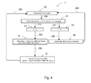
- the controlled heat flow is here the heat flow on each piston (for example Figure 1: 12) and the actuator is, for example, the amount of fuel, hereinafter referred to as Qcarb .
- the regulator is a regulator of type known as "PID" (for proportional action - integral - derivative) classic used generically for the control of the engines.
- Offset corresponds to the pitch of the variation of the quantity of fuel necessary to modify the thermal flows.
- this step is typically of the order 0.2 mg per shot. This quantity is determined during an initial phase of development depending on the engine and the sensitivities of the heat flows to this parameter.
- block 20 calculates heat flow to the piston (for example, FIG. 1: 12). It receives the results of the calculations made by the blocks 26 and 27 described below (links 260 and 270).
- the output of the block 27 is looped back, as previously indicated (link 270) on the heat flow calculation block 20 to the piston.
- the method according to the invention makes it possible to directly control, in a closed loop and in real time, the heat flux levels applied to the components of the engine.
- the invention applies equally to a diesel engine or a gasoline engine.
Landscapes
- Engineering & Computer Science (AREA)
- Chemical & Material Sciences (AREA)
- Combustion & Propulsion (AREA)
- Mechanical Engineering (AREA)
- General Engineering & Computer Science (AREA)
- Combined Controls Of Internal Combustion Engines (AREA)
- Electrical Control Of Air Or Fuel Supplied To Internal-Combustion Engine (AREA)
Applications Claiming Priority (1)
| Application Number | Priority Date | Filing Date | Title |
|---|---|---|---|
| FR0654387A FR2907509A1 (fr) | 2006-10-19 | 2006-10-19 | Procede d'estimation de parametres caracteristiques d'un moteur thermique et de controle des flux thermiques appliques a des composants de ce moteur |
Publications (1)
| Publication Number | Publication Date |
|---|---|
| EP1916404A1 true EP1916404A1 (de) | 2008-04-30 |
Family
ID=38055211
Family Applications (1)
| Application Number | Title | Priority Date | Filing Date |
|---|---|---|---|
| EP07301462A Withdrawn EP1916404A1 (de) | 2006-10-19 | 2007-10-12 | Verfahren zur Schätzung der charakteristischen Parameter einer Wärmekraftmaschine und zur Kontrolle der Wärmeströme, die Teile dieses Motors erreichen |
Country Status (2)
| Country | Link |
|---|---|
| EP (1) | EP1916404A1 (de) |
| FR (1) | FR2907509A1 (de) |
Cited By (2)
| Publication number | Priority date | Publication date | Assignee | Title |
|---|---|---|---|---|
| FR3102515A1 (fr) | 2019-10-29 | 2021-04-30 | Psa Automobiles Sa | Procédé d’estimation de l’état thermique d’un composant moteur et procédé de pilotage de commandes GMP |
| WO2023117060A1 (en) * | 2021-12-21 | 2023-06-29 | Wärtsilä Finland Oy | Method of and apparatus for controlling phasing of combustion of fuel in a multi-cylinder internal combustion engine |
Citations (5)
| Publication number | Priority date | Publication date | Assignee | Title |
|---|---|---|---|---|
| US5974792A (en) | 1995-09-18 | 1999-11-02 | Nippondenso Co., Ltd. | Internal combustion engine control with fast exhaust catalyst warm-up |
| EP1072766A1 (de) * | 1999-07-30 | 2001-01-31 | Valeo Thermique Moteur | Kühlungssteuervorrichtung einer Brennkraftmaschine eines Kraftfahrzeugs |
| EP1291514A2 (de) * | 2001-09-07 | 2003-03-12 | Mitsubishi Jidosha Kogyo Kabushiki Kaisha | Vorrichtung zur Steuerung der Abgasabgabe eines Motors |
| WO2003048550A1 (de) * | 2001-12-04 | 2003-06-12 | Robert Bosch Gmbh | Verfahren, computerprogramm, sowie steuer- und/oder regelgerät zum betreiben einer brennkraftmaschine |
| FR2854202A1 (fr) * | 2003-04-23 | 2004-10-29 | Bosch Gmbh Robert | Procede et dispositif de gestion d'un moteur a combustion interne |
-
2006
- 2006-10-19 FR FR0654387A patent/FR2907509A1/fr not_active Withdrawn
-
2007
- 2007-10-12 EP EP07301462A patent/EP1916404A1/de not_active Withdrawn
Patent Citations (5)
| Publication number | Priority date | Publication date | Assignee | Title |
|---|---|---|---|---|
| US5974792A (en) | 1995-09-18 | 1999-11-02 | Nippondenso Co., Ltd. | Internal combustion engine control with fast exhaust catalyst warm-up |
| EP1072766A1 (de) * | 1999-07-30 | 2001-01-31 | Valeo Thermique Moteur | Kühlungssteuervorrichtung einer Brennkraftmaschine eines Kraftfahrzeugs |
| EP1291514A2 (de) * | 2001-09-07 | 2003-03-12 | Mitsubishi Jidosha Kogyo Kabushiki Kaisha | Vorrichtung zur Steuerung der Abgasabgabe eines Motors |
| WO2003048550A1 (de) * | 2001-12-04 | 2003-06-12 | Robert Bosch Gmbh | Verfahren, computerprogramm, sowie steuer- und/oder regelgerät zum betreiben einer brennkraftmaschine |
| FR2854202A1 (fr) * | 2003-04-23 | 2004-10-29 | Bosch Gmbh Robert | Procede et dispositif de gestion d'un moteur a combustion interne |
Cited By (4)
| Publication number | Priority date | Publication date | Assignee | Title |
|---|---|---|---|---|
| FR3102515A1 (fr) | 2019-10-29 | 2021-04-30 | Psa Automobiles Sa | Procédé d’estimation de l’état thermique d’un composant moteur et procédé de pilotage de commandes GMP |
| WO2021084173A1 (fr) | 2019-10-29 | 2021-05-06 | Psa Automobiles Sa | Procédé d'estimation de l'état thermique d'un composant moteur et procédé de pilotage de commandes gmp |
| CN114616385A (zh) * | 2019-10-29 | 2022-06-10 | 标致雪铁龙汽车股份有限公司 | 发动机组成部件热状态估算方法和gmp命令操控方法 |
| WO2023117060A1 (en) * | 2021-12-21 | 2023-06-29 | Wärtsilä Finland Oy | Method of and apparatus for controlling phasing of combustion of fuel in a multi-cylinder internal combustion engine |
Also Published As
| Publication number | Publication date |
|---|---|
| FR2907509A1 (fr) | 2008-04-25 |
Similar Documents
| Publication | Publication Date | Title |
|---|---|---|
| EP1815118B1 (de) | Vorrichtung und verfahren zur bestimmung der von einem dieselmotor eines kraftfahrzeuges ausgestossenen nox-menge und diagnose- sowie motorverwaltungssystem mit einer derartigen vorrichtung | |
| WO2019110882A1 (fr) | Système et procédé de commande d'un moteur à combustion interne muni d'un système de post traitement des gaz d'échappement de type à catalyse sélective | |
| EP0954689A1 (de) | Steuervorrichtung für eine brennkraftmaschine mit gesteuerter zündung und direkter einspritzung | |
| WO2008084170A2 (fr) | Procede de regulation d'un moteur a combustion interne | |
| EP1916404A1 (de) | Verfahren zur Schätzung der charakteristischen Parameter einer Wärmekraftmaschine und zur Kontrolle der Wärmeströme, die Teile dieses Motors erreichen | |
| EP2430298B1 (de) | Schätzung der nox-konzentration (stickoxide) in einer brennkraftmaschine | |
| FR2847944A1 (fr) | Procede de regulation d'un melange air/carburant alimentant un moteur a combustion interne | |
| FR2835281A1 (fr) | Procede d'estimation de la masse d'air admise dans une chambre de combustion d'un moteur, et vehicule de mise en oeuvre | |
| EP1606501A1 (de) | Umgebungsdruckmessung in einer turbobrennkraftmaschine | |
| EP1671023A1 (de) | Motorluftzufuhrsteuerverfahren, das zum beispiel zur steuerung eines motors mit turbolader bestimmt ist | |
| WO2016012095A1 (fr) | Procede de determination de la pression totale dans le cylindre d'un moteur | |
| EP2256322B1 (de) | Einfluss der nox regelung auf die motorgeräuschregelung in einer brennkraftmaschine | |
| FR2903148A1 (fr) | Procede et installation de gestion d'un moteur a combustion interne. | |
| EP4234909B1 (de) | Verfahren zur steuerung des gemischverhältnisses des kraftstoffgemischs einer brennkraftmaschine eines kraftfahrzeugs | |
| WO2002040840A1 (fr) | Procede et dispositif de commande du fonctionnement d'un moteur a combustion interne a auto-allumage | |
| EP3004608B1 (de) | Verfahren zur messung des schadstoffausstosses eines verbrennungsmotors und verfahren zur steuerung des motors | |
| FR3084114A1 (fr) | Procede de controle de combustion dans un moteur | |
| FR2871195A1 (fr) | Procede et dispositif de gestion d'un moteur a combustion interne | |
| FR2793524A1 (fr) | Procede pour la mise en oeuvre d'un systeme d'alimentation en carburant de moteur a combustion interne | |
| FR2871521A1 (fr) | Systeme d'estimation de la pression dans le collecteur d'echappement d'un moteur diesel et procede de calibrage de ce systeme | |
| FR2894626A1 (fr) | Procede de gestion d'un moteur a combustion interne | |
| EP1647692A1 (de) | Ansaugluftsteuerverfahren für eine Brennkraftmaschine und Kraftfahrzeug zur Anwendung dieses Verfahrens | |
| EP3475556B1 (de) | Verfahren zur bestimmung der zündvorverstellung eines verbrennungsmotors und verfahren zur steuerung eines motors mittels eines solchen verfahrens | |
| FR3120659A1 (fr) | Calculateur de contrôle moteur pour véhicule automobile | |
| EP2807353B1 (de) | Verfahren zum thermischen schutz der abgasleitung eines verbrennungsmotors |
Legal Events
| Date | Code | Title | Description |
|---|---|---|---|
| PUAI | Public reference made under article 153(3) epc to a published international application that has entered the european phase |
Free format text: ORIGINAL CODE: 0009012 |
|
| AK | Designated contracting states |
Kind code of ref document: A1 Designated state(s): AT BE BG CH CY CZ DE DK EE ES FI FR GB GR HU IE IS IT LI LT LU LV MC MT NL PL PT RO SE SI SK TR |
|
| AX | Request for extension of the european patent |
Extension state: AL BA HR MK RS |
|
| 17P | Request for examination filed |
Effective date: 20081002 |
|
| AKX | Designation fees paid |
Designated state(s): AT BE BG CH CY CZ DE DK EE ES FI FR GB GR HU IE IS IT LI LT LU LV MC MT NL PL PT RO SE SI SK TR |
|
| GRAP | Despatch of communication of intention to grant a patent |
Free format text: ORIGINAL CODE: EPIDOSNIGR1 |
|
| STAA | Information on the status of an ep patent application or granted ep patent |
Free format text: STATUS: THE APPLICATION IS DEEMED TO BE WITHDRAWN |
|
| 18D | Application deemed to be withdrawn |
Effective date: 20100529 |