EP2807729B1 - Gehäuseanordnung für ein aktivteil einer elektrischen maschine - Google Patents
Gehäuseanordnung für ein aktivteil einer elektrischen maschine Download PDFInfo
- Publication number
- EP2807729B1 EP2807729B1 EP13707370.6A EP13707370A EP2807729B1 EP 2807729 B1 EP2807729 B1 EP 2807729B1 EP 13707370 A EP13707370 A EP 13707370A EP 2807729 B1 EP2807729 B1 EP 2807729B1
- Authority
- EP
- European Patent Office
- Prior art keywords
- housing
- active part
- arrangement
- oil
- housing arrangement
- Prior art date
- Legal status (The legal status is an assumption and is not a legal conclusion. Google has not performed a legal analysis and makes no representation as to the accuracy of the status listed.)
- Not-in-force
Links
Images

Classifications
-
- H—ELECTRICITY
- H02—GENERATION; CONVERSION OR DISTRIBUTION OF ELECTRIC POWER
- H02K—DYNAMO-ELECTRIC MACHINES
- H02K5/00—Casings; Enclosures; Supports
- H02K5/04—Casings or enclosures characterised by the shape, form or construction thereof
- H02K5/12—Casings or enclosures characterised by the shape, form or construction thereof specially adapted for operating in liquid or gas
- H02K5/128—Casings or enclosures characterised by the shape, form or construction thereof specially adapted for operating in liquid or gas using air-gap sleeves or air-gap discs
- H02K5/1285—Casings or enclosures characterised by the shape, form or construction thereof specially adapted for operating in liquid or gas using air-gap sleeves or air-gap discs of the submersible type
-
- H—ELECTRICITY
- H02—GENERATION; CONVERSION OR DISTRIBUTION OF ELECTRIC POWER
- H02K—DYNAMO-ELECTRIC MACHINES
- H02K9/00—Arrangements for cooling or ventilating
- H02K9/19—Arrangements for cooling or ventilating for machines with closed casing and closed-circuit cooling using a liquid cooling medium, e.g. oil
- H02K9/197—Arrangements for cooling or ventilating for machines with closed casing and closed-circuit cooling using a liquid cooling medium, e.g. oil in which the rotor or stator space is fluid-tight, e.g. to provide for different cooling media for rotor and stator
-
- H—ELECTRICITY
- H02—GENERATION; CONVERSION OR DISTRIBUTION OF ELECTRIC POWER
- H02K—DYNAMO-ELECTRIC MACHINES
- H02K7/00—Arrangements for handling mechanical energy structurally associated with dynamo-electric machines, e.g. structural association with mechanical driving motors or auxiliary dynamo-electric machines
- H02K7/18—Structural association of electric generators with mechanical driving motors, e.g. with turbines
- H02K7/1807—Rotary generators
- H02K7/1823—Rotary generators structurally associated with turbines or similar engines
Definitions
- the present invention relates to a housing arrangement for an active part of an electrical machine.
- the present invention also relates to an electrical machine.
- the hermetically sealed housing is therefore usually filled with an oil, in particular a transformer oil.
- the heat generated in the active part can be better dissipated to the housing of the electrical machine through the oil.
- the dielectric strength and thus the service life of the electrical machine can be increased by the oil.
- Such a housing for an electrical machine is usually made up of two housing elements.
- the housing element, which is arranged between the active parts of the electrical machine, should be designed as thin-walled as possible so that the electromagnetic forces generated by the first active part can be transmitted particularly effectively to the second active part.
- a so-called can is usually arranged between the active parts.
- Such a can can be made of a glass fiber reinforced plastic or the like and can have a wall thickness of a few millimeters. In large electrical machines, however, this results in the problem of insufficient strength of the can due to the static oil pressure. When the electrical machine is in operation, the oil in the interior of the housing also expands due to the heating. Thus, the thermal expansion of the oil exerts additional pressure on the can.
- the JP S60 28743 A describes an electrical machine which has a housing.
- the housing has an elastic material.
- oil around the stator expands as a result of the heating, the oil can be guided through an opening in the housing, whereby the elastic material is compressed.
- EP 0 543 280 A2 one water-cooled in the stator space and one air-cooled in the rotor space. Furthermore, pressure monitors can be provided to detect pressure fluctuations in the pressurized cooling system and to evaluate them for control and regulation purposes.
- the object of the present invention is to provide a housing arrangement for an active part of an electrical machine, which can be filled with oil, with which a reliable operation of the electrical machine can be made possible in a particularly simple manner.
- the housing arrangement according to the invention for an active part of an electrical machine comprises a first and a second housing element, through the connection of which a hermetically sealed housing is provided, wherein the active part can be arranged in an interior of the housing, and the interior of the housing can be filled with an oil and wherein the housing arrangement comprises a vacuum device which is designed to generate a lower internal pressure in the interior of the housing than a predetermined external pressure acting on the housing from outside.
- the internal pressure prevailing in the interior of the housing is made up of the pressure that acts on the housing as a result of the weight of the oil, and the pressure that arises when the oil heats up during operation of the electrical machine and expands as a result.
- the housing arrangement now includes a corresponding negative pressure device with which a negative pressure can be generated in the interior of the housing, so that the internal pressure in the interior of the housing is lower than the external pressure which acts on the housing from the outside.
- the external pressure can correspond to atmospheric pressure in a gaseous environment. If the housing arrangement or the electrical machine is used under water, the external pressure results from the water pressure, which is dependent on the depth in the water.
- the internal pressure can thus be adapted accordingly to the environment and the operating conditions of an electrical machine. There is therefore no risk that the weight of the oil and / or the thermal expansion of the oil will exert excessive pressure on one of the housing elements of the electrical machine.
- the vacuum device has an air-filled cavity which is in fluid connection with the interior of the housing.
- the vacuum device comprises a separate air-filled space or area that is connected to the housing.
- this cavity is fluidically connected to the interior of the housing through a corresponding opening.
- a corresponding negative pressure can now be generated so that the internal pressure in the housing is lower than the external pressure which acts on the housing from the outside.
- This air-filled cavity, in which a corresponding negative pressure is generated the internal pressure in the housing can be kept essentially constant. In this way, a vacuum device for a housing arrangement of an electrical machine can be provided in a simple manner.
- the vacuum device can be connected to a pump device which is designed to generate the internal pressure in the air-filled cavity.
- a vacuum can be generated in the air-filled cavity by means of a suitable vacuum pump, so that the desired internal pressure is established in the interior of the housing.
- the vacuum device or the cavity comprises a corresponding connection element to which such a pump device can be connected. It is also conceivable - not belonging to the invention - that the pump device is firmly connected to the housing arrangement. In this way, the internal pressure in the housing can be easily adjusted.
- the vacuum device is arranged on an outside of a lateral surface of the second housing element. If the vacuum device is arranged on the outside of the housing arrangement, it can easily be retrofitted to an existing housing arrangement for an electrical machine. In addition, a compact design can thus be achieved.
- the vacuum device is preferably arranged in an intended set-up position of the housing arrangement on an upper side of the housing arrangement. If the vacuum device is arranged on an upper side of the housing arrangement, a corresponding air-filled cavity is provided in the vacuum device, which cavity is not filled with oil. When the oil is in operation the electrical machine expands, the oil can escape in this cavity, which represents a corresponding compensation chamber. Furthermore, a corresponding inlet device, via which the interior of the housing can be filled with the oil, can be attached to the underside of the housing arrangement. If a negative pressure is now generated with the negative pressure device on the upper side of the housing, the oil can be sucked in from the lower side of the housing. By sucking in the oil by means of negative pressure, it is also dehydrated and thus has better electrical insulation properties.
- the housing arrangement comprises a pressure detection device for detecting the internal pressure in the interior of the housing.
- a pressure detection device can be provided by a corresponding pressure sensor and a corresponding pressure display device.
- the internal pressure in the housing can thus be monitored during and after the housing is filled with oil.
- an additional pressure detection device can also be provided which detects the external pressure.
- the internal pressure in the housing can easily be set manually as a function of the external pressure by means of the pump device. It is also conceivable that the internal pressure in the housing is automatically controlled or regulated.
- the housing arrangement preferably comprises a level detection device for detecting a level of the oil in the interior of the housing.
- a level detection device can be provided by a corresponding level sensor. It is also conceivable to provide a corresponding sight glass on the housing or on the vacuum device, by means of which the fill level in the interior of the housing can be optically detected. The fill level of the oil in the interior of the housing can thus be monitored during and after the filling with the oil.
- the electrical machine according to the invention comprises a housing arrangement described above, a first active part of the electrical machine is arranged in the interior of the housing of the housing arrangement and the interior is filled with the oil, and a second active part that is arranged to be movable to the first active part.
- Such an electrical machine can be used, for example, in underwater operation as a generator or as an ocean current turbine.
- Such ocean current generators often have a diameter of several meters.
- the internal pressure in the housing can be adjusted accordingly so that the housing is not damaged by the internal pressure generated by the thermal expansion of the oil, even with such dimensions.
- the internal pressure can be adapted accordingly to the depth at which the electrical machine is arranged underwater.
- such an electrical machine can be used in corresponding conveyor systems that include additional gears and in which different oil circuits are present.
- the electrical machine can also be used in the vicinity of aggressive or explosive gases.
- the second housing element of the housing arrangement is preferably mechanically coupled to the first active part at least in some areas. If a corresponding internal pressure is set in the interior of the housing arrangement which is lower than the external pressure, a mechanical force acts on the second housing element. The second housing element is supported on corresponding support elements of the first active part of the electrical machine. Mechanical deformation of the second housing element is thus prevented in a simple manner.
- a stator is arranged as the first active part of the electrical machine in the housing and the second housing element is designed as a can.
- the electrical machine is designed as a rotary electrical machine, the stator of the electrical machine being sealed off from the environment by the hermetically sealed housing.
- the rotor of the electrical machine can comprise corresponding permanent magnets, which are additionally sealed.
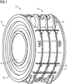
- FIG 1 shows in a perspective view an electrical machine 10, which is designed as a rotary electrical machine.
- the electrical machine 10 comprises a housing arrangement 12 in which a stator is arranged as an active part of the electrical machine 10.
- the stator of the electrical machine 10 which usually comprises corresponding windings, can thus be sealed off from the medium surrounding the electrical machine 10.
- the electrical machine 10 comprises a rotor 42.
- the electrical machine 10 can be used for underwater operation as an ocean current generator, the electrical machine 10 in this case being able to have a diameter of several meters.
- the housing arrangement 12 comprises a corresponding housing 20, which is formed by a first housing element 14 and a second Housing element 16 is formed.
- the first housing element 14 comprises a jacket surface 18 and a corresponding housing flange.
- the first housing element 14 can be formed from a metal, in particular from steel.
- the second housing element 16, which in FIG 1 cannot be seen, is designed as a can. This can has the shape of a hollow cylinder, the wall thickness usually being a few millimeters.
- the can can be formed for example from a glass fiber reinforced plastic or a carbon fiber reinforced plastic.
- the can is arranged in the air gap between the stator and rotor of the electrical machine 10.
- the airtight housing 20 is formed by assembling or connecting the first housing element 14 and the second housing element 16.
- the interior space 28 of the housing 20 can be filled with an oil, in particular a transformer oil.
- the heat generated in the stator during operation of the electrical machine 10 is thus better dissipated to the housing 20 of the electrical machine 10.
- the weight of the oil generates a pressure in the interior space 28 of the housing 20, which pressure acts on the housing 20.
- the stator of the electrical machine 10 and thus also the oil in the interior space 28 of the housing 20 are heated.
- the oil in the interior space 28 of the housing 20 expands.
- the pressure due to the weight and the thermal expansion of the oil acts in particular on the second housing element 16 or the can, since this has a small wall thickness and thus a low mechanical strength.
- the housing arrangement 12 has a vacuum device 22.
- an internal pressure can be generated in the interior space 28 of the housing 20 which is lower than the external pressure that acts on the housing 20 from the outside.
- the vacuum device 22 is preferably attached to an upper side 24 of the housing arrangement 12 when the housing arrangement 12 is in an intended installation position.
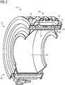
- FIG 2 shows the housing arrangement 10 according to FIG FIG 1 in a cut perspective view. It can be seen here that the vacuum device 22 has an air-filled cavity 26. Furthermore, the second housing element 16 or the can, which is arranged in the air gap between stator and rotor 42, can be seen.
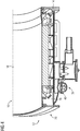
- This air-filled cavity 26 is particularly shown in the detailed view FIG 3 can be seen in which the rotor 42 is not shown.
- the air-filled cavity 26 is fluidically connected to the interior space 28 of the housing 20.
- the first housing element 14 according to the invention has a corresponding opening 30 on its lateral surface 18, which leads into the air-filled cavity 26.
- the vacuum device 22 has a connection device 32 which can be connected to a pump device.
- the connection device 32 can be designed as a suction valve.
- a mechanical force acts on the can 16.
- the can 16 is supported at least in some areas on the stator or corresponding support elements, so that it does not extend in the direction of the interior 28 of the housing 20 can deform.
- the housing arrangement 12 or the negative pressure device 22 comprises a filling level detection device.
- This can be provided by a corresponding fill level sensor.
- the negative pressure device 22 comprises a fill level detection device in the form of a sight glass 34.
- the fill level in the interior space 28 of the housing 20 or in the vacuum device 22 can be checked via this sight glass 34.
- the fill level of the oil can thus be monitored during and after the interior space 28 of the housing 20 is filled with the oil.
- the fill level of the oil should be selected so that the stator of the electrical machine 10 is completely covered with the oil.
- the maximum level of the oil level is in FIG 3 represented by line 36.
- the air-filled cavity 26 remains in the negative pressure device 22, in which a corresponding negative pressure can be generated and maintained by means of the pump device via the connection device 32.
- FIG 4 shows a further detailed view according to FIG 2 without rotor 42.
- a lower area of the housing arrangement 12 is shown.
- an inlet device 40 is arranged on an underside 38 of the housing arrangement 12.
- the inlet device 40 is designed as a corresponding valve which can be connected to a reservoir or a tank in which the oil is located.
- the inlet device 40 is fluidically connected to the interior space 28 of the housing 20.
- an oil reservoir can be connected to the inlet device 40.
- a corresponding negative pressure can then be generated in the air-filled cavity 26 of the negative pressure device 22.
- the oil is thus drawn into the interior space 28 of the housing 20 via the inlet device 40 on the underside 38 of the housing 20.
- the level of the oil in the interior space 28 of the housing 20 can be checked via a level sensor or via the sight glass 34.
- a pressure detection device (not shown here) can be provided in the interior space 28.
- a further pressure detection device can also be provided on the outside of the housing 20, with which the external pressure is determined.
- the internal pressure in the interior 28 of the Housing 20 can be adjusted depending on the external pressure.
Landscapes
- Engineering & Computer Science (AREA)
- Power Engineering (AREA)
- Motor Or Generator Frames (AREA)
Description
- Die vorliegende Erfindung betrifft eine Gehäuseanordnung für ein Aktivteil einer elektrischen Maschine. Überdies betrifft die vorliegende Erfindung eine elektrische Maschine.
- Bei elektrischen Maschinen kann der Bedarf bestehen, zumindest ein Aktivteil der elektrischen Maschine gegenüber dem umgebenden Medium abzudichten. Dies ist beispielsweise der Fall, wenn elektrische Maschinen im Unterwasserbetrieb eingesetzt werden sollen. Zudem ist eine entsprechende Abdichtung erforderlich, wenn eine elektrische Maschine in der Gegenwart von explosiven Gasen eingesetzt wird. Darüber hinaus ergibt sich die Notwenigkeit der Abdichtung zumindest eines Aktivteils der elektrischen Maschine, wenn aggressive Gase aus der Umgebung das Aktivteil beschädigen können. Eine bekannte Ausführungsform einer solchen Abdichtung kann durch ein Gehäuse ermöglicht werden, welches hermetisch abgeschlossen ausgebildet ist.
- Während des Betriebs der elektrischen Maschine entsteht in dem zumindest einen Aktivteil üblicherweise Wärme. Daher ist das hermetisch dichte Gehäuse üblicherweise mit einem Öl, insbesondere einem Transformatoröl, gefüllt. Durch das Öl kann die in dem Aktivteil entstehende Wärme besser an das Gehäuse der elektrischen Maschine abgeleitet werden. Zudem kann durch das Öl die Durchschlagfestigkeit und somit die Lebensdauer der elektrischen Maschine erhöht werden. Ein solches Gehäuse für eine elektrische Maschine ist üblicherweise aus zwei Gehäuseelementen aufgebaut. Dabei sollte das Gehäuseelement, das zwischen den Aktivteilen der elektrischen Maschine angeordnet ist, möglichst dünnwandig ausgebildet sein, damit die von dem ersten Aktivteil erzeugten elektromagnetischen Kräfte besonders effektiv auf das zweite Aktivteil übertragen werden können.
- Bei rotatorischen elektrischen Maschinen wird üblicherweise zwischen den Aktivteilen ein sogenanntes Spaltrohr angeordnet. Ein solches Spaltrohr kann aus einem glasfaserverstärkten Kunststoff oder dergleichen gefertigt sein und kann eine Wandstärke von wenigen Millimetern aufweisen. Damit ergibt sich bei großen elektrischen Maschinen jedoch das Problem der unzureichenden Festigkeit des Spaltrohrs aufgrund des statischen Öldrucks. Im Betrieb der elektrischen Maschine dehnt sich das Öl im Innenraum des Gehäuses aufgrund der Erwärmung zusätzlich aus. Somit wird durch die thermische Ausdehnung des Öls ein zusätzlicher Druck auf das Spaltrohr ausgeübt.
- Die
JP S60 28743 A - Zudem beschreibt die
EP 0 543 280 A2 einen im Statorraum wassergekühlten und einen im Rotorraum luftgekühlten Elektromotor. Ferner können Druckwächter vorgesehen sein, um Druckschwankungen in dem unter Druck stehenden Kühlsystem zu erfassen und für Kontroll- und Regelzwecke auszuwerten. - Es ist Aufgabe der vorliegenden Erfindung, eine Gehäuseanordnung für ein Aktivteil einer elektrischen Maschine, welches mit Öl befüllt werden kann, bereitzustellen, mit der auf besonders einfache Weise ein zuverlässiger Betrieb der elektrischen Maschine ermöglicht werden kann.
- Diese Aufgabe wird erfindungsgemäß durch eine Gehäuseanordnung gemäß Patentanspruch 1 und durch eine elektrische Maschine gemäß Patentanspruch 6 gelöst. Vorteilhafte Weiterbildungen der vorliegenden Erfindung sind in den Unteransprüchen angegeben.
- Die erfindungsgemäße Gehäuseanordnung für ein Aktivteil einer elektrischen Maschine umfasst ein erstes und ein zweites Gehäuseelement, durch deren Verbindung ein hermetisch abgeschlossenes Gehäuse bereitgestellt ist, wobei das Aktivteil in einem Innenraum des Gehäuses anordenbar ist, und der Innenraum des Gehäuses mit einem Öl befüllbar ist und wobei die Gehäuseanordnung eine Unterdruckeinrichtung umfasst, die dazu ausgebildet ist, in den Innenraum des Gehäuses einen im Vergleich zu einem von außen auf das Gehäuse wirkenden, vorgegebenen Außendruck geringeren Innendruck zu erzeugen.
- Der in dem Innenraum des Gehäuses herrschende Innendruck setzt sich aus dem Druck zusammen, der in Folge der Gewichtskraft des Öls auf das Gehäuse wirkt, und dem Druck, der entsteht, wenn sich das Öl in Betrieb der elektrischen Maschine erwärmt und dadurch ausdehnt. Die Gehäuseanordnung umfasst nun eine entsprechende Unterdruckeinrichtung, mit der im Innenraum des Gehäuses ein Unterdruck erzeugt werden kann, so dass der Innendruck im Innenraum des Gehäuses geringer ist als der Außendruck, der von außen auf das Gehäuse wirkt. Der Außendruck kann bei einer gasförmigen Umgebung dem Atmosphärendruck entsprechen. Wird die Gehäuseanordnung bzw. die elektrische Maschine unter Wasser eingesetzt, ergibt sich der Außendruck durch den Wasserdruck, der abhängig von der Tiefe im Wasser ist. Somit kann der Innendruck entsprechend an die Umgebung und die Betriebsbedingungen einer elektrischen Maschine angepasst werden. Somit besteht keine Gefahr, dass durch die Gewichtskraft des Öls und/oder die thermische Ausdehnung des Öls ein übermäßiger Druck auf eines der Gehäuseelemente der elektrischen Maschine ausgeübt wird.
- Zudem weist erfindungsgemäß die Unterdruckeinrichtung einen luftgefüllten Hohlraum auf, der mit dem Innenraum des Gehäuses in Fluidverbindung steht. Die Unterdruckeinrichtung umfasst einen separaten luftgefüllten Raum bzw. Bereich, der mit dem Gehäuse verbunden ist. Dieser Hohlraum ist erfindungsgemäß durch einen entsprechenden Durchbruch mit dem Innenraum des Gehäuses fluidisch verbunden. In diesem Hohlraum kann nun ein entsprechender Unterdruck erzeugt werden, so dass der Innendruck in dem Gehäuse geringer ist als der Außendruck, der von außen auf das Gehäuse wirkt. Durch diesen luftgefüllten Hohlraum, in dem ein entsprechender Unterdruck erzeugt wird, kann der Innendruck in dem Gehäuse im Wesentlichen konstant gehalten werden. Somit kann auf einfache Weise eine Unterdruckeinrichtung für eine Gehäuseanordnung einer elektrischen Maschine bereitgestellt werden.
- Ferner ist die Unterdruckeinrichtung erfindungsgemäß mit einer Pumpeneinrichtung verbindbar, die dazu ausgebildet ist, in dem luftgefüllten Hohlraum den Innendruck zu erzeugen. Durch eine entsprechende Vakuumpumpe kann in dem luftgefüllten Hohlraum ein Unterdruck erzeugt werden, so dass sich im Innenraum des Gehäuses der erwünschte Innendruck einstellt. Zu diesem Zweck umfasst die Unterdruckeinrichtung bzw. der Hohlraum erfindungsgemäss ein entsprechendes Anschlusselement, an dem eine solche Pumpeneinrichtung angeschlossen werden kann. Ebenso ist - nicht zur Erfindung gehörend - denkbar, dass die Pumpeneinrichtung fest mit der Gehäuseanordnung verbunden ist. Auf diese Weise kann der Innendruck in dem Gehäuse einfach angepasst werden.
- In einer Ausführungsform ist die Unterdruckeinrichtung an einer Außenseite einer Mantelfläche des zweiten Gehäuseelements angeordnet. Wenn die Unterdruckeinrichtung außenseitig an der Gehäuseanordnung angeordnet ist, kann er nachträglich einfach an eine bestehende Gehäuseanordnung für eine elektrische Maschine angebracht werden. Zudem kann somit eine kompakte Bauform erreicht werden.
- Bevorzugt ist die Unterdruckeinrichtung in einer bestimmungsgemäßen Aufstellposition der Gehäuseanordnung an einer Oberseite der Gehäuseanordnung angeordnet. Wenn die Unterdruckeinrichtung an einer Oberseite der Gehäuseanordnung angeordnet ist, wird in der Unterdruckeinrichtung ein entsprechender luftgefüllter Hohlraum bereitgestellt, der nicht mit Öl gefüllt ist. Wenn sich das Öl in Betrieb der elektrischen Maschine ausdehnt, kann das Öl in diesem Hohlraum ausweichen, der eine entsprechende Ausgleichskammer darstellt. Des Weiteren kann eine entsprechende Einlasseinrichtung, über die der Innenraum des Gehäuses mit dem Öl befüllt werden kann, an der Unterseite der Gehäuseanordnung angebracht sein. Wenn nun mit der Unterdruckeinrichtung an der Oberseite des Gehäuses ein Unterdruck erzeugt wird, kann das Öl von der Unterseite des Gehäuses eingesaugt werden. Durch das Einsaugen des Öls mittels Unterdruck wird dieses zusätzlich entwässert und erhält auf diese Weise bessere elektrische Isolationseigenschaften.
- In einer weiteren Ausführungsform umfasst die Gehäuseanordnung eine Druckerfassungseinrichtung zum Erfassen des Innendrucks im Innenraum des Gehäuses. Eine solche Druckerfassungseinrichtung kann durch einen entsprechenden Drucksensor und eine entsprechende Druckanzeigeeinrichtung bereitgestellt sein. Somit kann der Innendruck in dem Gehäuse während und nach dem Befüllen des Gehäuses mit Öl überwacht werden. Hierbei kann auch eine zusätzliche Druckerfassungseinrichtung vorgesehen sein, die den Außendruck erfasst. Somit kann der Innendruck in dem Gehäuse einfach in Abhängigkeit von dem Außendruck mittels der Pumpeneinrichtung manuell eingestellt werden. Dabei ist es auch denkbar, dass der Innendruck in dem Gehäuse automatisch gesteuert bzw. geregelt wird.
- Bevorzugt umfasst die Gehäuseanordnung eine Füllstandserfassungseinrichtung zum Erfassen eines Füllstands des Öls im Innenraum des Gehäuses. Eine solche Füllstandserfassungseinrichtung kann durch einen entsprechenden Füllstandssensor bereitgestellt werden. Ebenso ist es denkbar, an dem Gehäuse bzw. an der Unterdruckeinrichtung ein entsprechendes Schauglas vorzusehen, mittels welchem der Füllstand im Innenraum des Gehäuses optisch erfasst werden kann. Somit kann der Füllstand des Öls in dem Innenraum des Gehäuses während und nach dem Befüllen mit dem Öl überwacht werden.
- Die erfindungsgemäße elektrische Maschine umfasst eine zuvor beschriebene Gehäuseanordnung, wobei ein erstes Aktivteil der elektrischen Maschine in den Innenraum des Gehäuses der Gehäuseanordnung angeordnet ist und der Innenraum mit dem Öl befüllt ist, und einen zweiten Aktivteil, dass zum ersten Aktivteil bewegbar angeordnet ist. Die zuvor im Zusammenhang mit der erfindungsgemäßen Gehäuseanordnung beschriebenen Vorteile und Weiterbildungen können in gleicher Weise auf die elektrische Maschine übertragen werden.
- Eine solche elektrische Maschine kann beispielsweise in Unterwasserbetrieb als Generator bzw. als Meeresströmungsturbine verwendet werden. Solche Meeresströmungsgeneratoren weisen oft einen Durchmesser von mehreren Metern auf. In diesem Fall kann der Innendruck in dem Gehäuse entsprechend angepasst werden, dass auch bei solchen Dimensionen das Gehäuse durch den Innendruck, der durch die thermische Ausdehnung des Öls erzeugt wird, nicht beschädigt wird. Zudem kann der Innendruck entsprechend an die Tiefe angepasst werden, in der die elektrische Maschine unter Wasser angeordnet wird. Des Weiteren kann eine solche elektrische Maschine bei entsprechenden Förderanlagen verwendet werden, die zusätzliche Getriebe umfassen und bei denen verschiedene Ölkreisläufe vorhanden sind. Schließlich kann die elektrische Maschine auch in der Umgebung von aggressiven oder explosiven Gasen eingesetzt werden.
- Bevorzugt ist das zweite Gehäuseelement der Gehäuseanordnung zumindest bereichsweise mit dem erst Aktivteil mechanisch gekoppelt. Wenn in dem Innenraum der Gehäuseanordnung ein entsprechender Innendruck eingestellt wird, der geringer ist als der Außendruck, wirkt eine mechanische Kraft auf das zweite Gehäuseelement. Dabei ist das zweite Gehäuseelement an entsprechenden Stützelementen des ersten Aktivteils der elektrischen Maschine abgestützt. Somit wird eine mechanische Verformung des zweiten Gehäuseelements auf einfach Weise verhindert.
- In einer bevorzugten Ausführungsform ist ein Stator als das erste Aktivteil der elektrischen Maschine in dem Gehäuse angeordnet und das zweite Gehäuseelement ist als Spaltrohr ausgebildet. Die elektrische Maschine ist als rotatorische elektrische Maschine ausgebildet, wobei der Stator der elektrischen Maschine durch das hermetisch dichte Gehäuse gegenüber der Umgebung abgedichtet ist. Der Rotor der elektrischen Maschine kann entsprechende Permanentmagneten umfassen, die zusätzlich abgedichtet sind.
- Die vorliegende Erfindung wird nun anhand der beigefügten Zeichnungen näher erläutert. Dabei zeigen:
- FIG 1
- eine Perspektivdarstellung einer elektrischen Maschine in einer Gehäuseanordnung;
- FIG 2
- eine elektrische Maschine gemäß
FIG 1 in einer geschnittenen Perspektivdarstellung; - FIG 3
- eine Detailansicht gemäß
FIG 2 ohne Rotor; und - FIG 4
- eine weitere Detailansicht gemäß
FIG 2 ohne Rotor. - Die nachfolgend näher geschilderten Ausführungsbeispiele stellen bevorzugte Ausführungsformen der vorliegenden Erfindung dar.
-
FIG 1 zeigt in einer Perspektivdarstellung eine elektrische Maschine 10, die als rotatorische elektrische Maschine ausgebildet ist. Die elektrische Maschine 10 umfasst eine Gehäuseanordnung 12 in der ein Stator als Aktivteil der elektrischen Maschine 10 angeordnet ist. Somit kann der Stator der elektrischen Maschine 10, der üblicherweise entsprechende Wicklungen umfasst, gegenüber dem die elektrische Maschine 10 umgebenden Medium abgedichtet werden. Des Weiteren umfasst die elektrische Maschine 10 einen Rotor 42. Die elektrische Maschine 10 kann für den Unterwasserbetrieb als Meeresströmungsgenerator eingesetzt werden, wobei die elektrische Maschine 10 in diesem Fall ein Durchmesser von mehreren Metern aufweisen kann. - Die Gehäuseanordnung 12 umfasst ein entsprechendes Gehäuse 20, das durch ein erstes Gehäuseelement 14 und ein zweites Gehäuseelement 16 gebildet ist. Das erste Gehäuseelement 14 umfasst eine Mantelfläche 18 und einen entsprechenden Gehäuseflansch. Das erste Gehäuseelement 14 kann aus einem Metall, insbesondere aus Stahl, gebildet sein. Das zweite Gehäuseelement 16, das in
FIG 1 nicht zu erkennen ist, ist als Spaltrohr ausgebildet. Dieses Spaltrohr weist die Form eines Hohlzylinders auf, wobei die Wandstärke üblicherweise einige Millimeter beträgt. Das Spaltrohr kann beispielsweise aus einem glasfaserverstärkten Kunststoff oder einem kohlefaserverstärkten Kunststoff gebildet sein. Bei der elektrischen Maschine 10 ist das Spaltrohr in dem Luftspalt zwischen Stator und Rotor der elektrischen Maschine 10 angeordnet. - Durch den Zusammenbau bzw. durch die Verbindung des ersten Gehäuseelements 14 und des zweiten Gehäuseelements 16 wird das luftdichte Gehäuse 20 gebildet. Der Innenraum 28 des Gehäuses 20 kann mit einem Öl, insbesondere einem Trafoöl, befüllt werden. Somit wird die in Betrieb der elektrischen Maschine 10 in dem Stator erzeugte Wärme besser an das Gehäuse 20 der elektrischen Maschine 10 abgeleitet. Durch die Gewichtskraft des Öls wird im Innenraum 28 des Gehäuses 20 ein Druck erzeugt, der auf das Gehäuse 20 wirkt. Im Betrieb der elektrischen Maschine 10 erwärmt sich der Stator der elektrischen Maschine 10 und somit auch das Öl im Innenraum 28 des Gehäuses 20. In Folge der Erwärmung dehnt sich das Öl im Innenraum 28 des Gehäuses 20 aus. Der Druck durch die Gewichtskraft und die thermische Ausdehnung des Öls wirkt insbesondere auf das zweite Gehäuseelement 16 bzw. das Spaltrohr, da dieses eine geringe Wandstärke und somit eine geringe mechanische Festigkeit aufweist.
- Um erfindungsgemäß eine mechanische Verformung bzw. eine Beschädigung des als Spaltrohr ausgebildeten zweiten Gehäuseelements 16 zu verhindern, weist die Gehäuseanordnung 12 eine Unterdruckeinrichtung 22 auf. Mit der Unterdruckeinrichtung 22 kann in dem Innenraum 28 des Gehäuses 20 ein Innendruck erzeugt werden, der im Vergleich zu dem Außendruck, der von außen auf das Gehäuse 20 wirkt, geringer ist. Die Unterdruckeinrichtung 22 ist bevorzugt bei einer bestimmungsgemäßen Aufstellposition der Gehäuseanordnung 12 an einer Oberseite 24 der Gehäuseanordnung 12 angebracht.
-
FIG 2 zeigt die Gehäuseanordnung 10 gemäßFIG 1 in einer geschnittenen Perspektivdarstellung. Dabei ist zu erkennen, dass die Unterdruckeinrichtung 22 einen luftgefüllten Hohlraum 26 aufweist. Des Weiteren ist das zweite Gehäuseelement 16 bzw. das Spaltrohr zu erkennen, das in dem Luftspalt zwischen Stator und Rotor 42 angeordnet ist. - Dieser luftgefüllte Hohlraum 26 ist insbesondere in der Detailansicht gemäß
FIG 3 zu erkennen, in der der Rotor 42 nicht dargestellt ist. Der luftgefüllte Hohlraum 26 ist mit dem Innenraum 28 des Gehäuses 20 fluidisch verbunden. Zu diesem Zweck weist das erste Gehäuseelement 14 erfindungsgemäß an dessen Mantelfläche 18 einen entsprechenden Durchbruch 30 auf, der in den luftgefüllten Hohlraum 26 führt. Die Unterdruckeinrichtung 22 weist erfindungsgemäß eine Anschlusseinrichtung 32 auf, die mit einer Pumpeneinrichtung verbunden werden kann. Die Anschlusseinrichtung 32 kann als Absaugventil ausgebildet sein. Somit kann mittels einer Pumpeneinrichtung in dem luftgefüllten Hohlraum 26 der Unterdruckeinrichtung 22 ein Unterdruck erzeugt werden, sodass sich im Innenraum 28 des Gehäuses 20 ein Innendruck ausbildet, der geringer ist als der Außendruck, der von außen auf das Gehäuse 20 wirkt. Wenn in dem Innenraum 28 des Gehäuses 20 ein Unterdruck erzeugt wird, wirkt eine mechanische Kraft auf das Spaltrohr 16. Zu diesem Zweck ist das Spaltrohr 16 zumindest bereichsweise an dem Stator bzw. entsprechenden Stützelementen abgestützt, so dass es sich nicht in Richtung des Innenraums 28 des Gehäuses 20 verformen kann. - Des Weiteren umfasst die Gehäuseanordnung 12 bzw. die Unterdruckeinrichtung 22 eine Füllstandserfassungseinrichtung. Diese kann durch einen entsprechenden Füllstandsensor bereitgestellt werden. In dem hier dargestellten Ausführungsbeispiel umfasst die Unterdruckeinrichtung 22 eine Füllstandserfassungseinrichtung in Form eines Schauglases 34. Über dieses Schauglas 34 kann der Füllstand in dem Innenraum 28 des Gehäuses 20 bzw. in der Unterdruckeinrichtung 22 überprüft werden. Somit kann der Füllstand des Öls während und nach dem Befüllen des Innenraums 28 des Gehäuses 20 mit dem Öl überwacht werden. Der Füllstand des Öls sollte dabei so gewählt werden, dass der Stator der elektrischen Maschine 10 vollständig mit dem Öl bedeckt ist. Das maximale Niveau des Ölfüllstands ist in
FIG 3 durch die Linie 36 dargestellt. Somit bleibt in der Unterdruckeinrichtung 22 der luftgefüllte Hohlraum 26 bestehen, in dem mittels der Pumpeinrichtung über die Anschlusseinrichtung 32 ein entsprechender Unterdruck erzeugt und aufrechterhalten werden kann. -
FIG 4 zeigt eine weitere Detailansicht gemäßFIG 2 ohne Rotor 42. Dabei ist ein unterer Bereich der Gehäuseanordnung 12 dargestellt. In einer bestimmungsgemäßen Aufstellposition der elektrischen Maschine 10 ist dabei an einer Unterseite 38 der Gehäuseanordnung 12 eine Einlasseinrichtung 40 angeordnet. Die Einlasseinrichtung 40 ist als entsprechendes Ventil ausgebildet, das mit einem Reservoir bzw. einem Tank verbunden werden kann, indem sich das Öl befindet. Die Einlasseinrichtung 40 ist fluidisch mit dem Innenraum 28 des Gehäuses 20 verbunden. Beim Befüllen des Innenraums 28 des Gehäuses 20 kann ein Ölreservoir mit der Einlasseinrichtung 40 verbunden werden. Im Anschluss kann dem luftgefülltem Hohlraum 26 der Unterdruckeinrichtung 22 ein entsprechender Unterdruck erzeugt werden. Somit wird das Öl über die Einlasseinrichtung 40 an der Unterseite 38 des Gehäuses 20 in den Innenraum 28 des Gehäuses 20 gezogen. Über einen Füllstandsensor bzw. über das Schauglas 34 kann der Füllstand des Öls im Innenraum 28 des Gehäuses 20 überprüft werden. - Des Weiteren kann in dem Innenraum 28 eine hier nicht dargestellte Druckerfassungseinrichtung vorgesehen sein. Ebenso kann an der Außenseite des Gehäuses 20 eine weitere Druckerfassungseinrichtung vorgesehen sein, mit der der Außendruck ermittelt wird. Somit kann der Innendruck im Innenraum 28 des Gehäuses 20 in Abhängigkeit von dem Außendruck eingestellt werden.
Claims (8)
- Gehäuseanordnung (12) für ein Aktivteil einer elektrischen Maschine (10) mit einem ersten und einem zweiten Gehäuseelement (14,16), durch deren Verbindung ein hermetisch abgeschlossenes Gehäuse (20) bereitgestellt ist, wobei das zweite Gehäuseelement (16) ein Spaltrohr ist, wobei das Aktivteil in einem Innenraum (28) des Gehäuses (20) anordenbar ist, und wobei der Innenraum (28) des Gehäuses (20) mit einem Öl befüllbar ist, dadurch gekennzeich- net, dass die Gehäuseanordnung (12) eine Unterdruckeinrichtung (22) umfasst, die dazu ausgebildet ist, in dem Innenraum (28) des Gehäuses (20) einen im Vergleich zu einem von außen auf das Gehäuse (20) wirkenden, vorgegebenen Außendruck geringeren Innendruck zu erzeugen, dass die Unterdruckeinrichtung (22) einen luftgefüllten Hohlraum (26) aufweist, der mit dem Innenraum (28) des Gehäuses (20) in Fluidverbindung steht, dass zu diesem Zweck das erste Gehäuseelement (14) an dessen Mantelfläche (18) einen entsprechenden Durchbruch (30) aufweist, der in den luftgefüllten Hohlraum (26) führt und dass die Unterdruckeinrichtung (22) eine Anschlusseinrichtung (32) aufweist, die mit einer Pumpeneinrichtung verbindbar ist, wobei die Pumpeneinrichtung dazu ausgebildet ist, in dem luftgefüllten Hohlraum (26) den Innendruck zu erzeugen.
- Gehäuseanordnung (12) nach Anspruch 1, dadurch g ekennzeichnet, dass die Unterdruckeinrichtung (22) an einer Außenseite einer Mantelfläche (18) des zweiten Gehäuseelements (14) angeordnet ist.
- Gehäuseanordnung (12) nach einem der vorhergehenden Ansprüche, dadurch gekennzeichnet, dass die Unterdruckeinrichtung (22) in einer bestimmungsgemäßen Aufstellposition der Gehäuseanordnung (12) an einer Oberseite (24) der Gehäuseanordnung (10) angeordnet ist.
- Gehäuseanordnung (12) nach einem der vorhergehenden Ansprüche, dadurch gekennzeichnet, dass die Gehäuseanordnung (12) eine Druckerfassungseinrichtung zum Erfassen des Innendrucks im Innenraum (28) des Gehäuses (20) umfasst.
- Gehäuseanordnung (12) nach einem der vorhergehenden Ansprüche, dadurch gekennzeichnet, dass die Gehäuseanordnung (12) eine Füllstandserfassungseinrichtung zum Erfassen eines Füllstands des Öls im Innenraum (28) des Gehäuses (20) umfasst.
- Elektrische Maschine (10) mit- einer Gehäuseanordnung (12) nach einem der vorhergehenden Ansprüche, wobei ein erstes Aktivteil der elektrischen Maschine in dem Innenraum (28) des Gehäuses (20) der Gehäuseanordnung (12) angeordnet ist, und der Innenraum (28) mit einem Öl befüllt ist, und- einem zweiten Aktivteil, das zum ersten Aktivteil bewegbar angeordnet ist.
- Elektrische Maschine (10) nach Anspruch 6, dadurch gekennzeichnet, dass das zweite Gehäuseelement (16) der Gehäuseanordnung (12) zumindest bereichsweise mit dem ersten Aktivteil mechanisch gekoppelt ist.
- Elektrische Maschine (10) nach Anspruch 6 oder 7, da durch gekennzeichnet, dass ein Stator als das erste Aktivteil der elektrischen Maschine (10) in dem Gehäuse (20) angeordnet ist.
Applications Claiming Priority (2)
| Application Number | Priority Date | Filing Date | Title |
|---|---|---|---|
| DE102012203502A DE102012203502A1 (de) | 2012-03-06 | 2012-03-06 | Gehäuseanordnung für ein Aktivteil einer elektrischen Maschine |
| PCT/EP2013/054168 WO2013131820A2 (de) | 2012-03-06 | 2013-03-01 | Gehäuseanordnung für ein aktivteil einer elektrischen maschine |
Publications (2)
| Publication Number | Publication Date |
|---|---|
| EP2807729A2 EP2807729A2 (de) | 2014-12-03 |
| EP2807729B1 true EP2807729B1 (de) | 2021-02-17 |
Family
ID=47790215
Family Applications (1)
| Application Number | Title | Priority Date | Filing Date |
|---|---|---|---|
| EP13707370.6A Not-in-force EP2807729B1 (de) | 2012-03-06 | 2013-03-01 | Gehäuseanordnung für ein aktivteil einer elektrischen maschine |
Country Status (4)
| Country | Link |
|---|---|
| EP (1) | EP2807729B1 (de) |
| DE (1) | DE102012203502A1 (de) |
| ES (1) | ES2866474T3 (de) |
| WO (1) | WO2013131820A2 (de) |
Families Citing this family (2)
| Publication number | Priority date | Publication date | Assignee | Title |
|---|---|---|---|---|
| ES2711341T3 (es) | 2016-05-13 | 2019-05-03 | Nidec Asi S P A | Motor eléctrico |
| EP4024680A1 (de) * | 2021-01-05 | 2022-07-06 | Flender GmbH | Stator, verfahren zur simulation, computerprogrammprodukt |
Family Cites Families (10)
| Publication number | Priority date | Publication date | Assignee | Title |
|---|---|---|---|---|
| GB743778A (en) * | 1952-03-22 | 1956-01-25 | Mcgraw Electric Co | Improvements in electric motor pump unit |
| FR1237288A (fr) * | 1959-06-18 | 1960-07-29 | Acec | Dispositif de préservation et de régénération de l'huile pour les appareils électriques munis d'un conservateur |
| JPS5851756A (ja) * | 1981-09-24 | 1983-03-26 | Hitachi Ltd | 水中電動機 |
| JPS6028743A (ja) * | 1983-07-28 | 1985-02-13 | Mitsubishi Electric Corp | 液封形電動機 |
| JPH02193546A (ja) * | 1989-01-20 | 1990-07-31 | Mayekawa Mfg Co Ltd | キヤンドモーターの冷却方法 |
| DE4138268A1 (de) * | 1991-11-21 | 1993-05-27 | Klein Schanzlin & Becker Ag | Elektromotor |
| KR20010034383A (ko) * | 1998-01-26 | 2001-04-25 | 칼 하인쯔 호르닝어 | 제너레이터의 냉각을 위한 냉각 시스템 및 방법 |
| WO2000007282A1 (en) * | 1998-07-28 | 2000-02-10 | Sexton James H | Oil cooled motor and pump apparatus |
| US8629592B2 (en) * | 2009-06-25 | 2014-01-14 | General Electric Company | Hermetic sealing assembly and electrical device including the same |
| DE102009034158B4 (de) * | 2009-07-20 | 2023-11-16 | Flender Gmbh | Kapselung einer elektrischen Maschine |
-
2012
- 2012-03-06 DE DE102012203502A patent/DE102012203502A1/de not_active Withdrawn
-
2013
- 2013-03-01 WO PCT/EP2013/054168 patent/WO2013131820A2/de not_active Ceased
- 2013-03-01 ES ES13707370T patent/ES2866474T3/es active Active
- 2013-03-01 EP EP13707370.6A patent/EP2807729B1/de not_active Not-in-force
Non-Patent Citations (1)
| Title |
|---|
| None * |
Also Published As
| Publication number | Publication date |
|---|---|
| ES2866474T3 (es) | 2021-10-19 |
| DE102012203502A1 (de) | 2013-09-12 |
| EP2807729A2 (de) | 2014-12-03 |
| WO2013131820A3 (de) | 2014-09-04 |
| WO2013131820A2 (de) | 2013-09-12 |
Similar Documents
| Publication | Publication Date | Title |
|---|---|---|
| EP2862262B1 (de) | Kühlmantel mit einem dichtmittel | |
| DE102015107621B4 (de) | Elektromotor mit Luftspülfunktion | |
| DE2640239A1 (de) | Pumpe und pumpanlage fuer oelgefuellte elektrische kabel | |
| EP3149288B1 (de) | Demontageverfahren für gasturbinen und kalibriervorrichtung | |
| DE102009034158B4 (de) | Kapselung einer elektrischen Maschine | |
| EP2807729B1 (de) | Gehäuseanordnung für ein aktivteil einer elektrischen maschine | |
| DE102017219084A1 (de) | Elektrohydraulisches System mit einer hydraulischen Achse und mindestens einem geschlossenen Hydraulikkreislauf | |
| EP2071211B1 (de) | Schwingungsisolator zur Verwendung im Vakuum | |
| DE102012206846B4 (de) | Sicherheitsanordnung, Bauteil, umfassend eine Sicherheitsanordnung, Fahrzeug, umfassend eine Sicherheitsanordnung und Verwendung einer Sicherheitsanordnung | |
| EP3970265B1 (de) | Temperaturmesseinrichtung für einen stator einer elektrischen maschine mit hairpin- oder stab-wellenwicklungen | |
| EP3700065B1 (de) | Elektrischer antrieb | |
| EP3397423A1 (de) | Dämpfung von schwingungen einer maschine | |
| DE102015119265B4 (de) | Elektromotor mit einer Steuerelektronik | |
| DE102017223112A1 (de) | Gehäuseanordnung für eine Strömungsmaschine sowie Strömungsmaschinenanordnung mit einer solchen Gehäuseanordnung und Verfahren zum Herstellen der Gehäuseanordnung | |
| DE102018211038B4 (de) | Leckageregelungsvorrichtung, elektrische Maschine mit einer Leckageregelungsvorrichtung und Verfahren zum Betreiben einer Leckageregelungsvorrichtung | |
| WO2024170375A1 (de) | Näherungssensor | |
| DE102016114727B4 (de) | Verfahren zur Gleichlaufsteuerung eines Hydraulikzylindersystems sowie Mehrsäulen-Fahrzeughebebühne | |
| EP3623654B1 (de) | Magnetlagerung und schwungradspeicher | |
| WO2015058915A1 (de) | Aktor für ventile in verbrennungskraftmaschinen | |
| WO2022002667A1 (de) | Integrierte statorvorrichtung für eine elektrische maschine eines schwungmassenspeichers | |
| DE102019213700A1 (de) | Verfahren zum Herstellen einer toleranzausgeglichenen Verbindung zwischen einem ersten Bauteil und einem zweiten Bauteil und elektrischer Antrieb | |
| WO2019170518A1 (de) | Pumpenvorrichtung für ein systemgehäuse eines fahrzeugs | |
| DE102010041237A1 (de) | Pumpe mit Elektromotor | |
| DE102014221378B3 (de) | Vorrichtung zur Druckkompensation | |
| EP1515041A1 (de) | Hydraulikaggregat mit einem Vorratsbehälter für Hydraulik-Flüssigkeit und mit einer Motor-Pumpe-Einheit |
Legal Events
| Date | Code | Title | Description |
|---|---|---|---|
| PUAI | Public reference made under article 153(3) epc to a published international application that has entered the european phase |
Free format text: ORIGINAL CODE: 0009012 |
|
| 17P | Request for examination filed |
Effective date: 20140825 |
|
| AK | Designated contracting states |
Kind code of ref document: A2 Designated state(s): AL AT BE BG CH CY CZ DE DK EE ES FI FR GB GR HR HU IE IS IT LI LT LU LV MC MK MT NL NO PL PT RO RS SE SI SK SM TR |
|
| DAX | Request for extension of the european patent (deleted) | ||
| STAA | Information on the status of an ep patent application or granted ep patent |
Free format text: STATUS: EXAMINATION IS IN PROGRESS |
|
| 17Q | First examination report despatched |
Effective date: 20161026 |
|
| RAP1 | Party data changed (applicant data changed or rights of an application transferred) |
Owner name: SIEMENS AKTIENGESELLSCHAFT |
|
| GRAP | Despatch of communication of intention to grant a patent |
Free format text: ORIGINAL CODE: EPIDOSNIGR1 |
|
| STAA | Information on the status of an ep patent application or granted ep patent |
Free format text: STATUS: GRANT OF PATENT IS INTENDED |
|
| INTG | Intention to grant announced |
Effective date: 20201026 |
|
| RAP1 | Party data changed (applicant data changed or rights of an application transferred) |
Owner name: FLENDER GMBH |
|
| GRAS | Grant fee paid |
Free format text: ORIGINAL CODE: EPIDOSNIGR3 |
|
| GRAA | (expected) grant |
Free format text: ORIGINAL CODE: 0009210 |
|
| STAA | Information on the status of an ep patent application or granted ep patent |
Free format text: STATUS: THE PATENT HAS BEEN GRANTED |
|
| AK | Designated contracting states |
Kind code of ref document: B1 Designated state(s): AL AT BE BG CH CY CZ DE DK EE ES FI FR GB GR HR HU IE IS IT LI LT LU LV MC MK MT NL NO PL PT RO RS SE SI SK SM TR |
|
| REG | Reference to a national code |
Ref country code: GB Ref legal event code: FG4D Free format text: NOT ENGLISH |
|
| REG | Reference to a national code |
Ref country code: CH Ref legal event code: EP |
|
| REG | Reference to a national code |
Ref country code: DE Ref legal event code: R096 Ref document number: 502013015487 Country of ref document: DE |
|
| REG | Reference to a national code |
Ref country code: AT Ref legal event code: REF Ref document number: 1362781 Country of ref document: AT Kind code of ref document: T Effective date: 20210315 |
|
| REG | Reference to a national code |
Ref country code: IE Ref legal event code: FG4D Free format text: LANGUAGE OF EP DOCUMENT: GERMAN |
|
| REG | Reference to a national code |
Ref country code: DE Ref legal event code: R082 Ref document number: 502013015487 Country of ref document: DE Representative=s name: MICHALSKI HUETTERMANN & PARTNER PATENTANWAELTE, DE |
|
| REG | Reference to a national code |
Ref country code: LT Ref legal event code: MG9D |
|
| REG | Reference to a national code |
Ref country code: NL Ref legal event code: MP Effective date: 20210217 |
|
| PG25 | Lapsed in a contracting state [announced via postgrant information from national office to epo] |
Ref country code: GR Free format text: LAPSE BECAUSE OF FAILURE TO SUBMIT A TRANSLATION OF THE DESCRIPTION OR TO PAY THE FEE WITHIN THE PRESCRIBED TIME-LIMIT Effective date: 20210518 Ref country code: HR Free format text: LAPSE BECAUSE OF FAILURE TO SUBMIT A TRANSLATION OF THE DESCRIPTION OR TO PAY THE FEE WITHIN THE PRESCRIBED TIME-LIMIT Effective date: 20210217 Ref country code: FI Free format text: LAPSE BECAUSE OF FAILURE TO SUBMIT A TRANSLATION OF THE DESCRIPTION OR TO PAY THE FEE WITHIN THE PRESCRIBED TIME-LIMIT Effective date: 20210217 Ref country code: PT Free format text: LAPSE BECAUSE OF FAILURE TO SUBMIT A TRANSLATION OF THE DESCRIPTION OR TO PAY THE FEE WITHIN THE PRESCRIBED TIME-LIMIT Effective date: 20210617 Ref country code: LT Free format text: LAPSE BECAUSE OF FAILURE TO SUBMIT A TRANSLATION OF THE DESCRIPTION OR TO PAY THE FEE WITHIN THE PRESCRIBED TIME-LIMIT Effective date: 20210217 Ref country code: BG Free format text: LAPSE BECAUSE OF FAILURE TO SUBMIT A TRANSLATION OF THE DESCRIPTION OR TO PAY THE FEE WITHIN THE PRESCRIBED TIME-LIMIT Effective date: 20210517 Ref country code: NO Free format text: LAPSE BECAUSE OF FAILURE TO SUBMIT A TRANSLATION OF THE DESCRIPTION OR TO PAY THE FEE WITHIN THE PRESCRIBED TIME-LIMIT Effective date: 20210517 |
|
| PG25 | Lapsed in a contracting state [announced via postgrant information from national office to epo] |
Ref country code: SE Free format text: LAPSE BECAUSE OF FAILURE TO SUBMIT A TRANSLATION OF THE DESCRIPTION OR TO PAY THE FEE WITHIN THE PRESCRIBED TIME-LIMIT Effective date: 20210217 Ref country code: PL Free format text: LAPSE BECAUSE OF FAILURE TO SUBMIT A TRANSLATION OF THE DESCRIPTION OR TO PAY THE FEE WITHIN THE PRESCRIBED TIME-LIMIT Effective date: 20210217 Ref country code: NL Free format text: LAPSE BECAUSE OF FAILURE TO SUBMIT A TRANSLATION OF THE DESCRIPTION OR TO PAY THE FEE WITHIN THE PRESCRIBED TIME-LIMIT Effective date: 20210217 Ref country code: LV Free format text: LAPSE BECAUSE OF FAILURE TO SUBMIT A TRANSLATION OF THE DESCRIPTION OR TO PAY THE FEE WITHIN THE PRESCRIBED TIME-LIMIT Effective date: 20210217 Ref country code: RS Free format text: LAPSE BECAUSE OF FAILURE TO SUBMIT A TRANSLATION OF THE DESCRIPTION OR TO PAY THE FEE WITHIN THE PRESCRIBED TIME-LIMIT Effective date: 20210217 |
|
| PG25 | Lapsed in a contracting state [announced via postgrant information from national office to epo] |
Ref country code: IS Free format text: LAPSE BECAUSE OF FAILURE TO SUBMIT A TRANSLATION OF THE DESCRIPTION OR TO PAY THE FEE WITHIN THE PRESCRIBED TIME-LIMIT Effective date: 20210617 |
|
| REG | Reference to a national code |
Ref country code: ES Ref legal event code: FG2A Ref document number: 2866474 Country of ref document: ES Kind code of ref document: T3 Effective date: 20211019 |
|
| PG25 | Lapsed in a contracting state [announced via postgrant information from national office to epo] |
Ref country code: SM Free format text: LAPSE BECAUSE OF FAILURE TO SUBMIT A TRANSLATION OF THE DESCRIPTION OR TO PAY THE FEE WITHIN THE PRESCRIBED TIME-LIMIT Effective date: 20210217 Ref country code: CZ Free format text: LAPSE BECAUSE OF FAILURE TO SUBMIT A TRANSLATION OF THE DESCRIPTION OR TO PAY THE FEE WITHIN THE PRESCRIBED TIME-LIMIT Effective date: 20210217 Ref country code: EE Free format text: LAPSE BECAUSE OF FAILURE TO SUBMIT A TRANSLATION OF THE DESCRIPTION OR TO PAY THE FEE WITHIN THE PRESCRIBED TIME-LIMIT Effective date: 20210217 |
|
| REG | Reference to a national code |
Ref country code: CH Ref legal event code: PL |
|
| REG | Reference to a national code |
Ref country code: DE Ref legal event code: R097 Ref document number: 502013015487 Country of ref document: DE |
|
| PG25 | Lapsed in a contracting state [announced via postgrant information from national office to epo] |
Ref country code: SK Free format text: LAPSE BECAUSE OF FAILURE TO SUBMIT A TRANSLATION OF THE DESCRIPTION OR TO PAY THE FEE WITHIN THE PRESCRIBED TIME-LIMIT Effective date: 20210217 Ref country code: MC Free format text: LAPSE BECAUSE OF FAILURE TO SUBMIT A TRANSLATION OF THE DESCRIPTION OR TO PAY THE FEE WITHIN THE PRESCRIBED TIME-LIMIT Effective date: 20210217 Ref country code: DK Free format text: LAPSE BECAUSE OF FAILURE TO SUBMIT A TRANSLATION OF THE DESCRIPTION OR TO PAY THE FEE WITHIN THE PRESCRIBED TIME-LIMIT Effective date: 20210217 Ref country code: RO Free format text: LAPSE BECAUSE OF FAILURE TO SUBMIT A TRANSLATION OF THE DESCRIPTION OR TO PAY THE FEE WITHIN THE PRESCRIBED TIME-LIMIT Effective date: 20210217 |
|
| REG | Reference to a national code |
Ref country code: BE Ref legal event code: MM Effective date: 20210331 |
|
| PLBE | No opposition filed within time limit |
Free format text: ORIGINAL CODE: 0009261 |
|
| STAA | Information on the status of an ep patent application or granted ep patent |
Free format text: STATUS: NO OPPOSITION FILED WITHIN TIME LIMIT |
|
| 26N | No opposition filed |
Effective date: 20211118 |
|
| PG25 | Lapsed in a contracting state [announced via postgrant information from national office to epo] |
Ref country code: AL Free format text: LAPSE BECAUSE OF FAILURE TO SUBMIT A TRANSLATION OF THE DESCRIPTION OR TO PAY THE FEE WITHIN THE PRESCRIBED TIME-LIMIT Effective date: 20210217 Ref country code: CH Free format text: LAPSE BECAUSE OF NON-PAYMENT OF DUE FEES Effective date: 20210331 Ref country code: LI Free format text: LAPSE BECAUSE OF NON-PAYMENT OF DUE FEES Effective date: 20210331 Ref country code: LU Free format text: LAPSE BECAUSE OF NON-PAYMENT OF DUE FEES Effective date: 20210301 Ref country code: FR Free format text: LAPSE BECAUSE OF NON-PAYMENT OF DUE FEES Effective date: 20210417 Ref country code: IE Free format text: LAPSE BECAUSE OF NON-PAYMENT OF DUE FEES Effective date: 20210301 |
|
| PG25 | Lapsed in a contracting state [announced via postgrant information from national office to epo] |
Ref country code: SI Free format text: LAPSE BECAUSE OF FAILURE TO SUBMIT A TRANSLATION OF THE DESCRIPTION OR TO PAY THE FEE WITHIN THE PRESCRIBED TIME-LIMIT Effective date: 20210217 |
|
| PG25 | Lapsed in a contracting state [announced via postgrant information from national office to epo] |
Ref country code: IT Free format text: LAPSE BECAUSE OF FAILURE TO SUBMIT A TRANSLATION OF THE DESCRIPTION OR TO PAY THE FEE WITHIN THE PRESCRIBED TIME-LIMIT Effective date: 20210217 |
|
| PGFP | Annual fee paid to national office [announced via postgrant information from national office to epo] |
Ref country code: GB Payment date: 20220321 Year of fee payment: 10 Ref country code: DE Payment date: 20220329 Year of fee payment: 10 |
|
| REG | Reference to a national code |
Ref country code: AT Ref legal event code: MM01 Ref document number: 1362781 Country of ref document: AT Kind code of ref document: T Effective date: 20210301 |
|
| PG25 | Lapsed in a contracting state [announced via postgrant information from national office to epo] |
Ref country code: IS Free format text: LAPSE BECAUSE OF FAILURE TO SUBMIT A TRANSLATION OF THE DESCRIPTION OR TO PAY THE FEE WITHIN THE PRESCRIBED TIME-LIMIT Effective date: 20210617 |
|
| PG25 | Lapsed in a contracting state [announced via postgrant information from national office to epo] |
Ref country code: BE Free format text: LAPSE BECAUSE OF NON-PAYMENT OF DUE FEES Effective date: 20210331 |
|
| PGFP | Annual fee paid to national office [announced via postgrant information from national office to epo] |
Ref country code: ES Payment date: 20220527 Year of fee payment: 10 |
|
| PG25 | Lapsed in a contracting state [announced via postgrant information from national office to epo] |
Ref country code: AT Free format text: LAPSE BECAUSE OF NON-PAYMENT OF DUE FEES Effective date: 20210301 |
|
| PG25 | Lapsed in a contracting state [announced via postgrant information from national office to epo] |
Ref country code: HU Free format text: LAPSE BECAUSE OF FAILURE TO SUBMIT A TRANSLATION OF THE DESCRIPTION OR TO PAY THE FEE WITHIN THE PRESCRIBED TIME-LIMIT; INVALID AB INITIO Effective date: 20130301 |
|
| PG25 | Lapsed in a contracting state [announced via postgrant information from national office to epo] |
Ref country code: CY Free format text: LAPSE BECAUSE OF FAILURE TO SUBMIT A TRANSLATION OF THE DESCRIPTION OR TO PAY THE FEE WITHIN THE PRESCRIBED TIME-LIMIT Effective date: 20210217 |
|
| REG | Reference to a national code |
Ref country code: DE Ref legal event code: R119 Ref document number: 502013015487 Country of ref document: DE |
|
| GBPC | Gb: european patent ceased through non-payment of renewal fee |
Effective date: 20230301 |
|
| PG25 | Lapsed in a contracting state [announced via postgrant information from national office to epo] |
Ref country code: GB Free format text: LAPSE BECAUSE OF NON-PAYMENT OF DUE FEES Effective date: 20230301 |
|
| PG25 | Lapsed in a contracting state [announced via postgrant information from national office to epo] |
Ref country code: GB Free format text: LAPSE BECAUSE OF NON-PAYMENT OF DUE FEES Effective date: 20230301 Ref country code: DE Free format text: LAPSE BECAUSE OF NON-PAYMENT OF DUE FEES Effective date: 20231003 |
|
| PG25 | Lapsed in a contracting state [announced via postgrant information from national office to epo] |
Ref country code: MK Free format text: LAPSE BECAUSE OF FAILURE TO SUBMIT A TRANSLATION OF THE DESCRIPTION OR TO PAY THE FEE WITHIN THE PRESCRIBED TIME-LIMIT Effective date: 20210217 |
|
| REG | Reference to a national code |
Ref country code: ES Ref legal event code: FD2A Effective date: 20240430 |
|
| PG25 | Lapsed in a contracting state [announced via postgrant information from national office to epo] |
Ref country code: ES Free format text: LAPSE BECAUSE OF NON-PAYMENT OF DUE FEES Effective date: 20230302 |
|
| PG25 | Lapsed in a contracting state [announced via postgrant information from national office to epo] |
Ref country code: ES Free format text: LAPSE BECAUSE OF NON-PAYMENT OF DUE FEES Effective date: 20230302 |
|
| PG25 | Lapsed in a contracting state [announced via postgrant information from national office to epo] |
Ref country code: MT Free format text: LAPSE BECAUSE OF FAILURE TO SUBMIT A TRANSLATION OF THE DESCRIPTION OR TO PAY THE FEE WITHIN THE PRESCRIBED TIME-LIMIT Effective date: 20210217 |
|
| PG25 | Lapsed in a contracting state [announced via postgrant information from national office to epo] |
Ref country code: TR Free format text: LAPSE BECAUSE OF FAILURE TO SUBMIT A TRANSLATION OF THE DESCRIPTION OR TO PAY THE FEE WITHIN THE PRESCRIBED TIME-LIMIT Effective date: 20210217 |