EP2807729B1 - Ensemble carter pour partie active d'un moteur électrique - Google Patents
Ensemble carter pour partie active d'un moteur électrique Download PDFInfo
- Publication number
- EP2807729B1 EP2807729B1 EP13707370.6A EP13707370A EP2807729B1 EP 2807729 B1 EP2807729 B1 EP 2807729B1 EP 13707370 A EP13707370 A EP 13707370A EP 2807729 B1 EP2807729 B1 EP 2807729B1
- Authority
- EP
- European Patent Office
- Prior art keywords
- housing
- active part
- arrangement
- oil
- housing arrangement
- Prior art date
- Legal status (The legal status is an assumption and is not a legal conclusion. Google has not performed a legal analysis and makes no representation as to the accuracy of the status listed.)
- Not-in-force
Links
Images

Classifications
-
- H—ELECTRICITY
- H02—GENERATION; CONVERSION OR DISTRIBUTION OF ELECTRIC POWER
- H02K—DYNAMO-ELECTRIC MACHINES
- H02K5/00—Casings; Enclosures; Supports
- H02K5/04—Casings or enclosures characterised by the shape, form or construction thereof
- H02K5/12—Casings or enclosures characterised by the shape, form or construction thereof specially adapted for operating in liquid or gas
- H02K5/128—Casings or enclosures characterised by the shape, form or construction thereof specially adapted for operating in liquid or gas using air-gap sleeves or air-gap discs
- H02K5/1285—Casings or enclosures characterised by the shape, form or construction thereof specially adapted for operating in liquid or gas using air-gap sleeves or air-gap discs of the submersible type
-
- H—ELECTRICITY
- H02—GENERATION; CONVERSION OR DISTRIBUTION OF ELECTRIC POWER
- H02K—DYNAMO-ELECTRIC MACHINES
- H02K9/00—Arrangements for cooling or ventilating
- H02K9/19—Arrangements for cooling or ventilating for machines with closed casing and closed-circuit cooling using a liquid cooling medium, e.g. oil
- H02K9/197—Arrangements for cooling or ventilating for machines with closed casing and closed-circuit cooling using a liquid cooling medium, e.g. oil in which the rotor or stator space is fluid-tight, e.g. to provide for different cooling media for rotor and stator
-
- H—ELECTRICITY
- H02—GENERATION; CONVERSION OR DISTRIBUTION OF ELECTRIC POWER
- H02K—DYNAMO-ELECTRIC MACHINES
- H02K7/00—Arrangements for handling mechanical energy structurally associated with dynamo-electric machines, e.g. structural association with mechanical driving motors or auxiliary dynamo-electric machines
- H02K7/18—Structural association of electric generators with mechanical driving motors, e.g. with turbines
- H02K7/1807—Rotary generators
- H02K7/1823—Rotary generators structurally associated with turbines or similar engines
Definitions
- the present invention relates to a housing arrangement for an active part of an electrical machine.
- the present invention also relates to an electrical machine.
- the hermetically sealed housing is therefore usually filled with an oil, in particular a transformer oil.
- the heat generated in the active part can be better dissipated to the housing of the electrical machine through the oil.
- the dielectric strength and thus the service life of the electrical machine can be increased by the oil.
- Such a housing for an electrical machine is usually made up of two housing elements.
- the housing element, which is arranged between the active parts of the electrical machine, should be designed as thin-walled as possible so that the electromagnetic forces generated by the first active part can be transmitted particularly effectively to the second active part.
- a so-called can is usually arranged between the active parts.
- Such a can can be made of a glass fiber reinforced plastic or the like and can have a wall thickness of a few millimeters. In large electrical machines, however, this results in the problem of insufficient strength of the can due to the static oil pressure. When the electrical machine is in operation, the oil in the interior of the housing also expands due to the heating. Thus, the thermal expansion of the oil exerts additional pressure on the can.
- the JP S60 28743 A describes an electrical machine which has a housing.
- the housing has an elastic material.
- oil around the stator expands as a result of the heating, the oil can be guided through an opening in the housing, whereby the elastic material is compressed.
- EP 0 543 280 A2 one water-cooled in the stator space and one air-cooled in the rotor space. Furthermore, pressure monitors can be provided to detect pressure fluctuations in the pressurized cooling system and to evaluate them for control and regulation purposes.
- the object of the present invention is to provide a housing arrangement for an active part of an electrical machine, which can be filled with oil, with which a reliable operation of the electrical machine can be made possible in a particularly simple manner.
- the housing arrangement according to the invention for an active part of an electrical machine comprises a first and a second housing element, through the connection of which a hermetically sealed housing is provided, wherein the active part can be arranged in an interior of the housing, and the interior of the housing can be filled with an oil and wherein the housing arrangement comprises a vacuum device which is designed to generate a lower internal pressure in the interior of the housing than a predetermined external pressure acting on the housing from outside.
- the internal pressure prevailing in the interior of the housing is made up of the pressure that acts on the housing as a result of the weight of the oil, and the pressure that arises when the oil heats up during operation of the electrical machine and expands as a result.
- the housing arrangement now includes a corresponding negative pressure device with which a negative pressure can be generated in the interior of the housing, so that the internal pressure in the interior of the housing is lower than the external pressure which acts on the housing from the outside.
- the external pressure can correspond to atmospheric pressure in a gaseous environment. If the housing arrangement or the electrical machine is used under water, the external pressure results from the water pressure, which is dependent on the depth in the water.
- the internal pressure can thus be adapted accordingly to the environment and the operating conditions of an electrical machine. There is therefore no risk that the weight of the oil and / or the thermal expansion of the oil will exert excessive pressure on one of the housing elements of the electrical machine.
- the vacuum device has an air-filled cavity which is in fluid connection with the interior of the housing.
- the vacuum device comprises a separate air-filled space or area that is connected to the housing.
- this cavity is fluidically connected to the interior of the housing through a corresponding opening.
- a corresponding negative pressure can now be generated so that the internal pressure in the housing is lower than the external pressure which acts on the housing from the outside.
- This air-filled cavity, in which a corresponding negative pressure is generated the internal pressure in the housing can be kept essentially constant. In this way, a vacuum device for a housing arrangement of an electrical machine can be provided in a simple manner.
- the vacuum device can be connected to a pump device which is designed to generate the internal pressure in the air-filled cavity.
- a vacuum can be generated in the air-filled cavity by means of a suitable vacuum pump, so that the desired internal pressure is established in the interior of the housing.
- the vacuum device or the cavity comprises a corresponding connection element to which such a pump device can be connected. It is also conceivable - not belonging to the invention - that the pump device is firmly connected to the housing arrangement. In this way, the internal pressure in the housing can be easily adjusted.
- the vacuum device is arranged on an outside of a lateral surface of the second housing element. If the vacuum device is arranged on the outside of the housing arrangement, it can easily be retrofitted to an existing housing arrangement for an electrical machine. In addition, a compact design can thus be achieved.
- the vacuum device is preferably arranged in an intended set-up position of the housing arrangement on an upper side of the housing arrangement. If the vacuum device is arranged on an upper side of the housing arrangement, a corresponding air-filled cavity is provided in the vacuum device, which cavity is not filled with oil. When the oil is in operation the electrical machine expands, the oil can escape in this cavity, which represents a corresponding compensation chamber. Furthermore, a corresponding inlet device, via which the interior of the housing can be filled with the oil, can be attached to the underside of the housing arrangement. If a negative pressure is now generated with the negative pressure device on the upper side of the housing, the oil can be sucked in from the lower side of the housing. By sucking in the oil by means of negative pressure, it is also dehydrated and thus has better electrical insulation properties.
- the housing arrangement comprises a pressure detection device for detecting the internal pressure in the interior of the housing.
- a pressure detection device can be provided by a corresponding pressure sensor and a corresponding pressure display device.
- the internal pressure in the housing can thus be monitored during and after the housing is filled with oil.
- an additional pressure detection device can also be provided which detects the external pressure.
- the internal pressure in the housing can easily be set manually as a function of the external pressure by means of the pump device. It is also conceivable that the internal pressure in the housing is automatically controlled or regulated.
- the housing arrangement preferably comprises a level detection device for detecting a level of the oil in the interior of the housing.
- a level detection device can be provided by a corresponding level sensor. It is also conceivable to provide a corresponding sight glass on the housing or on the vacuum device, by means of which the fill level in the interior of the housing can be optically detected. The fill level of the oil in the interior of the housing can thus be monitored during and after the filling with the oil.
- the electrical machine according to the invention comprises a housing arrangement described above, a first active part of the electrical machine is arranged in the interior of the housing of the housing arrangement and the interior is filled with the oil, and a second active part that is arranged to be movable to the first active part.
- Such an electrical machine can be used, for example, in underwater operation as a generator or as an ocean current turbine.
- Such ocean current generators often have a diameter of several meters.
- the internal pressure in the housing can be adjusted accordingly so that the housing is not damaged by the internal pressure generated by the thermal expansion of the oil, even with such dimensions.
- the internal pressure can be adapted accordingly to the depth at which the electrical machine is arranged underwater.
- such an electrical machine can be used in corresponding conveyor systems that include additional gears and in which different oil circuits are present.
- the electrical machine can also be used in the vicinity of aggressive or explosive gases.
- the second housing element of the housing arrangement is preferably mechanically coupled to the first active part at least in some areas. If a corresponding internal pressure is set in the interior of the housing arrangement which is lower than the external pressure, a mechanical force acts on the second housing element. The second housing element is supported on corresponding support elements of the first active part of the electrical machine. Mechanical deformation of the second housing element is thus prevented in a simple manner.
- a stator is arranged as the first active part of the electrical machine in the housing and the second housing element is designed as a can.
- the electrical machine is designed as a rotary electrical machine, the stator of the electrical machine being sealed off from the environment by the hermetically sealed housing.
- the rotor of the electrical machine can comprise corresponding permanent magnets, which are additionally sealed.
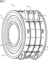
- FIG 1 shows in a perspective view an electrical machine 10, which is designed as a rotary electrical machine.
- the electrical machine 10 comprises a housing arrangement 12 in which a stator is arranged as an active part of the electrical machine 10.
- the stator of the electrical machine 10 which usually comprises corresponding windings, can thus be sealed off from the medium surrounding the electrical machine 10.
- the electrical machine 10 comprises a rotor 42.
- the electrical machine 10 can be used for underwater operation as an ocean current generator, the electrical machine 10 in this case being able to have a diameter of several meters.
- the housing arrangement 12 comprises a corresponding housing 20, which is formed by a first housing element 14 and a second Housing element 16 is formed.
- the first housing element 14 comprises a jacket surface 18 and a corresponding housing flange.
- the first housing element 14 can be formed from a metal, in particular from steel.
- the second housing element 16, which in FIG 1 cannot be seen, is designed as a can. This can has the shape of a hollow cylinder, the wall thickness usually being a few millimeters.
- the can can be formed for example from a glass fiber reinforced plastic or a carbon fiber reinforced plastic.
- the can is arranged in the air gap between the stator and rotor of the electrical machine 10.
- the airtight housing 20 is formed by assembling or connecting the first housing element 14 and the second housing element 16.
- the interior space 28 of the housing 20 can be filled with an oil, in particular a transformer oil.
- the heat generated in the stator during operation of the electrical machine 10 is thus better dissipated to the housing 20 of the electrical machine 10.
- the weight of the oil generates a pressure in the interior space 28 of the housing 20, which pressure acts on the housing 20.
- the stator of the electrical machine 10 and thus also the oil in the interior space 28 of the housing 20 are heated.
- the oil in the interior space 28 of the housing 20 expands.
- the pressure due to the weight and the thermal expansion of the oil acts in particular on the second housing element 16 or the can, since this has a small wall thickness and thus a low mechanical strength.
- the housing arrangement 12 has a vacuum device 22.
- an internal pressure can be generated in the interior space 28 of the housing 20 which is lower than the external pressure that acts on the housing 20 from the outside.
- the vacuum device 22 is preferably attached to an upper side 24 of the housing arrangement 12 when the housing arrangement 12 is in an intended installation position.
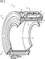
- FIG 2 shows the housing arrangement 10 according to FIG FIG 1 in a cut perspective view. It can be seen here that the vacuum device 22 has an air-filled cavity 26. Furthermore, the second housing element 16 or the can, which is arranged in the air gap between stator and rotor 42, can be seen.
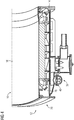
- This air-filled cavity 26 is particularly shown in the detailed view FIG 3 can be seen in which the rotor 42 is not shown.
- the air-filled cavity 26 is fluidically connected to the interior space 28 of the housing 20.
- the first housing element 14 according to the invention has a corresponding opening 30 on its lateral surface 18, which leads into the air-filled cavity 26.
- the vacuum device 22 has a connection device 32 which can be connected to a pump device.
- the connection device 32 can be designed as a suction valve.
- a mechanical force acts on the can 16.
- the can 16 is supported at least in some areas on the stator or corresponding support elements, so that it does not extend in the direction of the interior 28 of the housing 20 can deform.
- the housing arrangement 12 or the negative pressure device 22 comprises a filling level detection device.
- This can be provided by a corresponding fill level sensor.
- the negative pressure device 22 comprises a fill level detection device in the form of a sight glass 34.
- the fill level in the interior space 28 of the housing 20 or in the vacuum device 22 can be checked via this sight glass 34.
- the fill level of the oil can thus be monitored during and after the interior space 28 of the housing 20 is filled with the oil.
- the fill level of the oil should be selected so that the stator of the electrical machine 10 is completely covered with the oil.
- the maximum level of the oil level is in FIG 3 represented by line 36.
- the air-filled cavity 26 remains in the negative pressure device 22, in which a corresponding negative pressure can be generated and maintained by means of the pump device via the connection device 32.
- FIG 4 shows a further detailed view according to FIG 2 without rotor 42.
- a lower area of the housing arrangement 12 is shown.
- an inlet device 40 is arranged on an underside 38 of the housing arrangement 12.
- the inlet device 40 is designed as a corresponding valve which can be connected to a reservoir or a tank in which the oil is located.
- the inlet device 40 is fluidically connected to the interior space 28 of the housing 20.
- an oil reservoir can be connected to the inlet device 40.
- a corresponding negative pressure can then be generated in the air-filled cavity 26 of the negative pressure device 22.
- the oil is thus drawn into the interior space 28 of the housing 20 via the inlet device 40 on the underside 38 of the housing 20.
- the level of the oil in the interior space 28 of the housing 20 can be checked via a level sensor or via the sight glass 34.
- a pressure detection device (not shown here) can be provided in the interior space 28.
- a further pressure detection device can also be provided on the outside of the housing 20, with which the external pressure is determined.
- the internal pressure in the interior 28 of the Housing 20 can be adjusted depending on the external pressure.
Landscapes
- Engineering & Computer Science (AREA)
- Power Engineering (AREA)
- Motor Or Generator Frames (AREA)
Claims (8)
- Agencement (12) de carcasse d'une partie active d'une machine (10) électrique, comprenant un premier et un deuxième éléments (14, 16) de carcasse, dont la liaison donne une carcasse (20) fermée de manière hermétique, le deuxième élément (16) de carcasse étant une gaine, la partie active pouvant être mise dans un espace (28) intérieur de la carcasse (20) et l'espace (28) intérieur de la carcasse (20) pouvant être empli d'huile, caractérisé en ce que l'agencement (12) de carcasse comprend un dispositif (22) de mise en dépression, qui est constitué pour produire, dans l'espace (28) intérieur de la carcasse (20), une pression intérieure plus basse qu'une pression extérieure donnée à l'avance, agissant de l'extérieur sur la carcasse (20), en ce que le dispositif (22) de mise en dépression a une cavité (26) remplie d'air, qui est en liaison fluidique avec l'espace (28) intérieur de la carcasse (20), en ce qu'à cette fin, le premier élément (14) de la carcasse a, sur sa surface (18) latérale, une traversée (30) correspondante, qui conduit à la cavité (26) remplie d'air et en ce que le dispositif (22) de mise en dépression a un dispositif de raccord, qui peut être relié à un dispositif de pompage, le dispositif de pompage étant constitué pour produire la pression intérieure dans la cavité (26) remplie d'air.
- Agencement (12) de carcasse suivant la revendication 1, caractérisé en ce que le dispositif (22) de mise en dépression est disposé sur une face extérieure d'une surface (18) latérale du deuxième élément (14) de la carcasse.
- Agencement (12) de carcasse suivant l'une des revendications précédentes, caractérisé en ce que le dispositif (22) de mise en dépression est, dans une position de montage conforme aux prescriptions de l'agencement (12) de carcasse, disposé sur un côté (24) supérieur de l'agencement (10) de carcasse.
- Agencement (12) de carcasse suivant l'une des revendications précédentes, caractérisé en ce que l'agencement (12) de carcasse comprend un dispositif de détection de la pression, pour détecter la pression dans l'espace (28) intérieur de la carcasse (20).
- Agencement (12) de carcasse suivant l'une des revendications précédentes, caractérisé en ce que l'agencement (12) de carcasse comprend un dispositif de détection de niveau pour la détection d'un niveau de l'huile dans l'espace (28) intérieur de la carcasse (20).
- Machine (10) électrique, comprenant- un agencement (12) de carcasse suivant l'une des revendications précédentes, une première partie active de la machine électrique étant disposée dans l'espace (28) intérieur de la carcasse (20) de l'agencement (12) de carcasse, et l'espace (28) intérieur étant empli d'huile, et- une deuxième partie active, qui est montée mobile par rapport à la première partie active.
- Machine (10) électrique suivant la revendication 6, caractérisée en ce que le deuxième élément (16) de carcasse de l'agencement (12) de carcasse est couplé mécaniquement, au moins par endroits, à la première partie active.
- Machine (10) électrique suivant la revendication 6 ou 7, caractérisée en ce qu'un stator est disposé dans la carcasse (20), comme première partie active de la machine (10) électrique.
Applications Claiming Priority (2)
| Application Number | Priority Date | Filing Date | Title |
|---|---|---|---|
| DE102012203502A DE102012203502A1 (de) | 2012-03-06 | 2012-03-06 | Gehäuseanordnung für ein Aktivteil einer elektrischen Maschine |
| PCT/EP2013/054168 WO2013131820A2 (fr) | 2012-03-06 | 2013-03-01 | Ensemble carter pour partie active d'un moteur électrique |
Publications (2)
| Publication Number | Publication Date |
|---|---|
| EP2807729A2 EP2807729A2 (fr) | 2014-12-03 |
| EP2807729B1 true EP2807729B1 (fr) | 2021-02-17 |
Family
ID=47790215
Family Applications (1)
| Application Number | Title | Priority Date | Filing Date |
|---|---|---|---|
| EP13707370.6A Not-in-force EP2807729B1 (fr) | 2012-03-06 | 2013-03-01 | Ensemble carter pour partie active d'un moteur électrique |
Country Status (4)
| Country | Link |
|---|---|
| EP (1) | EP2807729B1 (fr) |
| DE (1) | DE102012203502A1 (fr) |
| ES (1) | ES2866474T3 (fr) |
| WO (1) | WO2013131820A2 (fr) |
Families Citing this family (2)
| Publication number | Priority date | Publication date | Assignee | Title |
|---|---|---|---|---|
| ES2711341T3 (es) | 2016-05-13 | 2019-05-03 | Nidec Asi S P A | Motor eléctrico |
| EP4024680A1 (fr) * | 2021-01-05 | 2022-07-06 | Flender GmbH | Stator, procédé de simulation, produit programme informatique |
Family Cites Families (10)
| Publication number | Priority date | Publication date | Assignee | Title |
|---|---|---|---|---|
| GB743778A (en) * | 1952-03-22 | 1956-01-25 | Mcgraw Electric Co | Improvements in electric motor pump unit |
| FR1237288A (fr) * | 1959-06-18 | 1960-07-29 | Acec | Dispositif de préservation et de régénération de l'huile pour les appareils électriques munis d'un conservateur |
| JPS5851756A (ja) * | 1981-09-24 | 1983-03-26 | Hitachi Ltd | 水中電動機 |
| JPS6028743A (ja) * | 1983-07-28 | 1985-02-13 | Mitsubishi Electric Corp | 液封形電動機 |
| JPH02193546A (ja) * | 1989-01-20 | 1990-07-31 | Mayekawa Mfg Co Ltd | キヤンドモーターの冷却方法 |
| DE4138268A1 (de) * | 1991-11-21 | 1993-05-27 | Klein Schanzlin & Becker Ag | Elektromotor |
| KR20010034383A (ko) * | 1998-01-26 | 2001-04-25 | 칼 하인쯔 호르닝어 | 제너레이터의 냉각을 위한 냉각 시스템 및 방법 |
| WO2000007282A1 (fr) * | 1998-07-28 | 2000-02-10 | Sexton James H | Motopompe refroidie par huile |
| US8629592B2 (en) * | 2009-06-25 | 2014-01-14 | General Electric Company | Hermetic sealing assembly and electrical device including the same |
| DE102009034158B4 (de) * | 2009-07-20 | 2023-11-16 | Flender Gmbh | Kapselung einer elektrischen Maschine |
-
2012
- 2012-03-06 DE DE102012203502A patent/DE102012203502A1/de not_active Withdrawn
-
2013
- 2013-03-01 WO PCT/EP2013/054168 patent/WO2013131820A2/fr not_active Ceased
- 2013-03-01 ES ES13707370T patent/ES2866474T3/es active Active
- 2013-03-01 EP EP13707370.6A patent/EP2807729B1/fr not_active Not-in-force
Non-Patent Citations (1)
| Title |
|---|
| None * |
Also Published As
| Publication number | Publication date |
|---|---|
| ES2866474T3 (es) | 2021-10-19 |
| DE102012203502A1 (de) | 2013-09-12 |
| EP2807729A2 (fr) | 2014-12-03 |
| WO2013131820A3 (fr) | 2014-09-04 |
| WO2013131820A2 (fr) | 2013-09-12 |
Similar Documents
| Publication | Publication Date | Title |
|---|---|---|
| EP2862262B1 (fr) | Chemise de refroidissement dotée d'un moyen d'étanchéité | |
| DE102015107621B4 (de) | Elektromotor mit Luftspülfunktion | |
| DE2640239A1 (de) | Pumpe und pumpanlage fuer oelgefuellte elektrische kabel | |
| EP3149288B1 (fr) | Procédé de désassemblage pour turbines à gaz et dispositif de calibrage | |
| DE102009034158B4 (de) | Kapselung einer elektrischen Maschine | |
| EP2807729B1 (fr) | Ensemble carter pour partie active d'un moteur électrique | |
| DE102017219084A1 (de) | Elektrohydraulisches System mit einer hydraulischen Achse und mindestens einem geschlossenen Hydraulikkreislauf | |
| EP2071211B1 (fr) | Isolant de vibrations destiné à l'utilisation sous vide | |
| DE102012206846B4 (de) | Sicherheitsanordnung, Bauteil, umfassend eine Sicherheitsanordnung, Fahrzeug, umfassend eine Sicherheitsanordnung und Verwendung einer Sicherheitsanordnung | |
| EP3970265B1 (fr) | Dispositif de mesure de température pour un stator d'une machine électrique comprenant des enroulements ondulés en épingle à cheveux ou en barre | |
| EP3700065B1 (fr) | Entraînement électrique | |
| EP3397423A1 (fr) | Amortissement de vibrations dans une machine | |
| DE102015119265B4 (de) | Elektromotor mit einer Steuerelektronik | |
| DE102017223112A1 (de) | Gehäuseanordnung für eine Strömungsmaschine sowie Strömungsmaschinenanordnung mit einer solchen Gehäuseanordnung und Verfahren zum Herstellen der Gehäuseanordnung | |
| DE102018211038B4 (de) | Leckageregelungsvorrichtung, elektrische Maschine mit einer Leckageregelungsvorrichtung und Verfahren zum Betreiben einer Leckageregelungsvorrichtung | |
| WO2024170375A1 (fr) | Capteur de proximité | |
| DE102016114727B4 (de) | Verfahren zur Gleichlaufsteuerung eines Hydraulikzylindersystems sowie Mehrsäulen-Fahrzeughebebühne | |
| EP3623654B1 (fr) | Palier magnétique et accumulateur à volant d'inertie | |
| WO2015058915A1 (fr) | Actionneur pour soupapes dans des moteurs à combustion interne | |
| WO2022002667A1 (fr) | Dispositif de stator intégré pour une machine électrique d'un système de stockage d'énergie par volant d'inertie | |
| DE102019213700A1 (de) | Verfahren zum Herstellen einer toleranzausgeglichenen Verbindung zwischen einem ersten Bauteil und einem zweiten Bauteil und elektrischer Antrieb | |
| WO2019170518A1 (fr) | Dispositif de pompage pour un boîtier de système d'un véhicule | |
| DE102010041237A1 (de) | Pumpe mit Elektromotor | |
| DE102014221378B3 (de) | Vorrichtung zur Druckkompensation | |
| EP1515041A1 (fr) | Groupe hydraulique avec un réservoir pour liquide hydraulique et une unité motopompe |
Legal Events
| Date | Code | Title | Description |
|---|---|---|---|
| PUAI | Public reference made under article 153(3) epc to a published international application that has entered the european phase |
Free format text: ORIGINAL CODE: 0009012 |
|
| 17P | Request for examination filed |
Effective date: 20140825 |
|
| AK | Designated contracting states |
Kind code of ref document: A2 Designated state(s): AL AT BE BG CH CY CZ DE DK EE ES FI FR GB GR HR HU IE IS IT LI LT LU LV MC MK MT NL NO PL PT RO RS SE SI SK SM TR |
|
| DAX | Request for extension of the european patent (deleted) | ||
| STAA | Information on the status of an ep patent application or granted ep patent |
Free format text: STATUS: EXAMINATION IS IN PROGRESS |
|
| 17Q | First examination report despatched |
Effective date: 20161026 |
|
| RAP1 | Party data changed (applicant data changed or rights of an application transferred) |
Owner name: SIEMENS AKTIENGESELLSCHAFT |
|
| GRAP | Despatch of communication of intention to grant a patent |
Free format text: ORIGINAL CODE: EPIDOSNIGR1 |
|
| STAA | Information on the status of an ep patent application or granted ep patent |
Free format text: STATUS: GRANT OF PATENT IS INTENDED |
|
| INTG | Intention to grant announced |
Effective date: 20201026 |
|
| RAP1 | Party data changed (applicant data changed or rights of an application transferred) |
Owner name: FLENDER GMBH |
|
| GRAS | Grant fee paid |
Free format text: ORIGINAL CODE: EPIDOSNIGR3 |
|
| GRAA | (expected) grant |
Free format text: ORIGINAL CODE: 0009210 |
|
| STAA | Information on the status of an ep patent application or granted ep patent |
Free format text: STATUS: THE PATENT HAS BEEN GRANTED |
|
| AK | Designated contracting states |
Kind code of ref document: B1 Designated state(s): AL AT BE BG CH CY CZ DE DK EE ES FI FR GB GR HR HU IE IS IT LI LT LU LV MC MK MT NL NO PL PT RO RS SE SI SK SM TR |
|
| REG | Reference to a national code |
Ref country code: GB Ref legal event code: FG4D Free format text: NOT ENGLISH |
|
| REG | Reference to a national code |
Ref country code: CH Ref legal event code: EP |
|
| REG | Reference to a national code |
Ref country code: DE Ref legal event code: R096 Ref document number: 502013015487 Country of ref document: DE |
|
| REG | Reference to a national code |
Ref country code: AT Ref legal event code: REF Ref document number: 1362781 Country of ref document: AT Kind code of ref document: T Effective date: 20210315 |
|
| REG | Reference to a national code |
Ref country code: IE Ref legal event code: FG4D Free format text: LANGUAGE OF EP DOCUMENT: GERMAN |
|
| REG | Reference to a national code |
Ref country code: DE Ref legal event code: R082 Ref document number: 502013015487 Country of ref document: DE Representative=s name: MICHALSKI HUETTERMANN & PARTNER PATENTANWAELTE, DE |
|
| REG | Reference to a national code |
Ref country code: LT Ref legal event code: MG9D |
|
| REG | Reference to a national code |
Ref country code: NL Ref legal event code: MP Effective date: 20210217 |
|
| PG25 | Lapsed in a contracting state [announced via postgrant information from national office to epo] |
Ref country code: GR Free format text: LAPSE BECAUSE OF FAILURE TO SUBMIT A TRANSLATION OF THE DESCRIPTION OR TO PAY THE FEE WITHIN THE PRESCRIBED TIME-LIMIT Effective date: 20210518 Ref country code: HR Free format text: LAPSE BECAUSE OF FAILURE TO SUBMIT A TRANSLATION OF THE DESCRIPTION OR TO PAY THE FEE WITHIN THE PRESCRIBED TIME-LIMIT Effective date: 20210217 Ref country code: FI Free format text: LAPSE BECAUSE OF FAILURE TO SUBMIT A TRANSLATION OF THE DESCRIPTION OR TO PAY THE FEE WITHIN THE PRESCRIBED TIME-LIMIT Effective date: 20210217 Ref country code: PT Free format text: LAPSE BECAUSE OF FAILURE TO SUBMIT A TRANSLATION OF THE DESCRIPTION OR TO PAY THE FEE WITHIN THE PRESCRIBED TIME-LIMIT Effective date: 20210617 Ref country code: LT Free format text: LAPSE BECAUSE OF FAILURE TO SUBMIT A TRANSLATION OF THE DESCRIPTION OR TO PAY THE FEE WITHIN THE PRESCRIBED TIME-LIMIT Effective date: 20210217 Ref country code: BG Free format text: LAPSE BECAUSE OF FAILURE TO SUBMIT A TRANSLATION OF THE DESCRIPTION OR TO PAY THE FEE WITHIN THE PRESCRIBED TIME-LIMIT Effective date: 20210517 Ref country code: NO Free format text: LAPSE BECAUSE OF FAILURE TO SUBMIT A TRANSLATION OF THE DESCRIPTION OR TO PAY THE FEE WITHIN THE PRESCRIBED TIME-LIMIT Effective date: 20210517 |
|
| PG25 | Lapsed in a contracting state [announced via postgrant information from national office to epo] |
Ref country code: SE Free format text: LAPSE BECAUSE OF FAILURE TO SUBMIT A TRANSLATION OF THE DESCRIPTION OR TO PAY THE FEE WITHIN THE PRESCRIBED TIME-LIMIT Effective date: 20210217 Ref country code: PL Free format text: LAPSE BECAUSE OF FAILURE TO SUBMIT A TRANSLATION OF THE DESCRIPTION OR TO PAY THE FEE WITHIN THE PRESCRIBED TIME-LIMIT Effective date: 20210217 Ref country code: NL Free format text: LAPSE BECAUSE OF FAILURE TO SUBMIT A TRANSLATION OF THE DESCRIPTION OR TO PAY THE FEE WITHIN THE PRESCRIBED TIME-LIMIT Effective date: 20210217 Ref country code: LV Free format text: LAPSE BECAUSE OF FAILURE TO SUBMIT A TRANSLATION OF THE DESCRIPTION OR TO PAY THE FEE WITHIN THE PRESCRIBED TIME-LIMIT Effective date: 20210217 Ref country code: RS Free format text: LAPSE BECAUSE OF FAILURE TO SUBMIT A TRANSLATION OF THE DESCRIPTION OR TO PAY THE FEE WITHIN THE PRESCRIBED TIME-LIMIT Effective date: 20210217 |
|
| PG25 | Lapsed in a contracting state [announced via postgrant information from national office to epo] |
Ref country code: IS Free format text: LAPSE BECAUSE OF FAILURE TO SUBMIT A TRANSLATION OF THE DESCRIPTION OR TO PAY THE FEE WITHIN THE PRESCRIBED TIME-LIMIT Effective date: 20210617 |
|
| REG | Reference to a national code |
Ref country code: ES Ref legal event code: FG2A Ref document number: 2866474 Country of ref document: ES Kind code of ref document: T3 Effective date: 20211019 |
|
| PG25 | Lapsed in a contracting state [announced via postgrant information from national office to epo] |
Ref country code: SM Free format text: LAPSE BECAUSE OF FAILURE TO SUBMIT A TRANSLATION OF THE DESCRIPTION OR TO PAY THE FEE WITHIN THE PRESCRIBED TIME-LIMIT Effective date: 20210217 Ref country code: CZ Free format text: LAPSE BECAUSE OF FAILURE TO SUBMIT A TRANSLATION OF THE DESCRIPTION OR TO PAY THE FEE WITHIN THE PRESCRIBED TIME-LIMIT Effective date: 20210217 Ref country code: EE Free format text: LAPSE BECAUSE OF FAILURE TO SUBMIT A TRANSLATION OF THE DESCRIPTION OR TO PAY THE FEE WITHIN THE PRESCRIBED TIME-LIMIT Effective date: 20210217 |
|
| REG | Reference to a national code |
Ref country code: CH Ref legal event code: PL |
|
| REG | Reference to a national code |
Ref country code: DE Ref legal event code: R097 Ref document number: 502013015487 Country of ref document: DE |
|
| PG25 | Lapsed in a contracting state [announced via postgrant information from national office to epo] |
Ref country code: SK Free format text: LAPSE BECAUSE OF FAILURE TO SUBMIT A TRANSLATION OF THE DESCRIPTION OR TO PAY THE FEE WITHIN THE PRESCRIBED TIME-LIMIT Effective date: 20210217 Ref country code: MC Free format text: LAPSE BECAUSE OF FAILURE TO SUBMIT A TRANSLATION OF THE DESCRIPTION OR TO PAY THE FEE WITHIN THE PRESCRIBED TIME-LIMIT Effective date: 20210217 Ref country code: DK Free format text: LAPSE BECAUSE OF FAILURE TO SUBMIT A TRANSLATION OF THE DESCRIPTION OR TO PAY THE FEE WITHIN THE PRESCRIBED TIME-LIMIT Effective date: 20210217 Ref country code: RO Free format text: LAPSE BECAUSE OF FAILURE TO SUBMIT A TRANSLATION OF THE DESCRIPTION OR TO PAY THE FEE WITHIN THE PRESCRIBED TIME-LIMIT Effective date: 20210217 |
|
| REG | Reference to a national code |
Ref country code: BE Ref legal event code: MM Effective date: 20210331 |
|
| PLBE | No opposition filed within time limit |
Free format text: ORIGINAL CODE: 0009261 |
|
| STAA | Information on the status of an ep patent application or granted ep patent |
Free format text: STATUS: NO OPPOSITION FILED WITHIN TIME LIMIT |
|
| 26N | No opposition filed |
Effective date: 20211118 |
|
| PG25 | Lapsed in a contracting state [announced via postgrant information from national office to epo] |
Ref country code: AL Free format text: LAPSE BECAUSE OF FAILURE TO SUBMIT A TRANSLATION OF THE DESCRIPTION OR TO PAY THE FEE WITHIN THE PRESCRIBED TIME-LIMIT Effective date: 20210217 Ref country code: CH Free format text: LAPSE BECAUSE OF NON-PAYMENT OF DUE FEES Effective date: 20210331 Ref country code: LI Free format text: LAPSE BECAUSE OF NON-PAYMENT OF DUE FEES Effective date: 20210331 Ref country code: LU Free format text: LAPSE BECAUSE OF NON-PAYMENT OF DUE FEES Effective date: 20210301 Ref country code: FR Free format text: LAPSE BECAUSE OF NON-PAYMENT OF DUE FEES Effective date: 20210417 Ref country code: IE Free format text: LAPSE BECAUSE OF NON-PAYMENT OF DUE FEES Effective date: 20210301 |
|
| PG25 | Lapsed in a contracting state [announced via postgrant information from national office to epo] |
Ref country code: SI Free format text: LAPSE BECAUSE OF FAILURE TO SUBMIT A TRANSLATION OF THE DESCRIPTION OR TO PAY THE FEE WITHIN THE PRESCRIBED TIME-LIMIT Effective date: 20210217 |
|
| PG25 | Lapsed in a contracting state [announced via postgrant information from national office to epo] |
Ref country code: IT Free format text: LAPSE BECAUSE OF FAILURE TO SUBMIT A TRANSLATION OF THE DESCRIPTION OR TO PAY THE FEE WITHIN THE PRESCRIBED TIME-LIMIT Effective date: 20210217 |
|
| PGFP | Annual fee paid to national office [announced via postgrant information from national office to epo] |
Ref country code: GB Payment date: 20220321 Year of fee payment: 10 Ref country code: DE Payment date: 20220329 Year of fee payment: 10 |
|
| REG | Reference to a national code |
Ref country code: AT Ref legal event code: MM01 Ref document number: 1362781 Country of ref document: AT Kind code of ref document: T Effective date: 20210301 |
|
| PG25 | Lapsed in a contracting state [announced via postgrant information from national office to epo] |
Ref country code: IS Free format text: LAPSE BECAUSE OF FAILURE TO SUBMIT A TRANSLATION OF THE DESCRIPTION OR TO PAY THE FEE WITHIN THE PRESCRIBED TIME-LIMIT Effective date: 20210617 |
|
| PG25 | Lapsed in a contracting state [announced via postgrant information from national office to epo] |
Ref country code: BE Free format text: LAPSE BECAUSE OF NON-PAYMENT OF DUE FEES Effective date: 20210331 |
|
| PGFP | Annual fee paid to national office [announced via postgrant information from national office to epo] |
Ref country code: ES Payment date: 20220527 Year of fee payment: 10 |
|
| PG25 | Lapsed in a contracting state [announced via postgrant information from national office to epo] |
Ref country code: AT Free format text: LAPSE BECAUSE OF NON-PAYMENT OF DUE FEES Effective date: 20210301 |
|
| PG25 | Lapsed in a contracting state [announced via postgrant information from national office to epo] |
Ref country code: HU Free format text: LAPSE BECAUSE OF FAILURE TO SUBMIT A TRANSLATION OF THE DESCRIPTION OR TO PAY THE FEE WITHIN THE PRESCRIBED TIME-LIMIT; INVALID AB INITIO Effective date: 20130301 |
|
| PG25 | Lapsed in a contracting state [announced via postgrant information from national office to epo] |
Ref country code: CY Free format text: LAPSE BECAUSE OF FAILURE TO SUBMIT A TRANSLATION OF THE DESCRIPTION OR TO PAY THE FEE WITHIN THE PRESCRIBED TIME-LIMIT Effective date: 20210217 |
|
| REG | Reference to a national code |
Ref country code: DE Ref legal event code: R119 Ref document number: 502013015487 Country of ref document: DE |
|
| GBPC | Gb: european patent ceased through non-payment of renewal fee |
Effective date: 20230301 |
|
| PG25 | Lapsed in a contracting state [announced via postgrant information from national office to epo] |
Ref country code: GB Free format text: LAPSE BECAUSE OF NON-PAYMENT OF DUE FEES Effective date: 20230301 |
|
| PG25 | Lapsed in a contracting state [announced via postgrant information from national office to epo] |
Ref country code: GB Free format text: LAPSE BECAUSE OF NON-PAYMENT OF DUE FEES Effective date: 20230301 Ref country code: DE Free format text: LAPSE BECAUSE OF NON-PAYMENT OF DUE FEES Effective date: 20231003 |
|
| PG25 | Lapsed in a contracting state [announced via postgrant information from national office to epo] |
Ref country code: MK Free format text: LAPSE BECAUSE OF FAILURE TO SUBMIT A TRANSLATION OF THE DESCRIPTION OR TO PAY THE FEE WITHIN THE PRESCRIBED TIME-LIMIT Effective date: 20210217 |
|
| REG | Reference to a national code |
Ref country code: ES Ref legal event code: FD2A Effective date: 20240430 |
|
| PG25 | Lapsed in a contracting state [announced via postgrant information from national office to epo] |
Ref country code: ES Free format text: LAPSE BECAUSE OF NON-PAYMENT OF DUE FEES Effective date: 20230302 |
|
| PG25 | Lapsed in a contracting state [announced via postgrant information from national office to epo] |
Ref country code: ES Free format text: LAPSE BECAUSE OF NON-PAYMENT OF DUE FEES Effective date: 20230302 |
|
| PG25 | Lapsed in a contracting state [announced via postgrant information from national office to epo] |
Ref country code: MT Free format text: LAPSE BECAUSE OF FAILURE TO SUBMIT A TRANSLATION OF THE DESCRIPTION OR TO PAY THE FEE WITHIN THE PRESCRIBED TIME-LIMIT Effective date: 20210217 |
|
| PG25 | Lapsed in a contracting state [announced via postgrant information from national office to epo] |
Ref country code: TR Free format text: LAPSE BECAUSE OF FAILURE TO SUBMIT A TRANSLATION OF THE DESCRIPTION OR TO PAY THE FEE WITHIN THE PRESCRIBED TIME-LIMIT Effective date: 20210217 |