EP2807737B1 - Gestapelter spannungsquellenumrichter mit getrennten gleichstromquellen - Google Patents
Gestapelter spannungsquellenumrichter mit getrennten gleichstromquellen Download PDFInfo
- Publication number
- EP2807737B1 EP2807737B1 EP13741065.0A EP13741065A EP2807737B1 EP 2807737 B1 EP2807737 B1 EP 2807737B1 EP 13741065 A EP13741065 A EP 13741065A EP 2807737 B1 EP2807737 B1 EP 2807737B1
- Authority
- EP
- European Patent Office
- Prior art keywords
- inverter
- full bridge
- voltage source
- voltage
- stacked
- Prior art date
- Legal status (The legal status is an assumption and is not a legal conclusion. Google has not performed a legal analysis and makes no representation as to the accuracy of the status listed.)
- Active
Links
Images







Classifications
-
- H—ELECTRICITY
- H02—GENERATION; CONVERSION OR DISTRIBUTION OF ELECTRIC POWER
- H02J—ELECTRIC POWER NETWORKS; CIRCUIT ARRANGEMENTS OR SYSTEMS FOR SUPPLYING OR DISTRIBUTING ELECTRIC POWER; SYSTEMS FOR STORING ELECTRIC ENERGY
- H02J3/00—Circuit arrangements for AC mains or AC distribution networks
- H02J3/38—Arrangements for feeding a single network from two or more generators or sources in parallel; Arrangements for feeding already energised networks from additional generators or sources in parallel
- H02J3/381—Dispersed generators
-
- H—ELECTRICITY
- H02—GENERATION; CONVERSION OR DISTRIBUTION OF ELECTRIC POWER
- H02M—APPARATUS FOR CONVERSION BETWEEN AC AND AC, BETWEEN AC AND DC, OR BETWEEN DC AND DC, AND FOR USE WITH MAINS OR SIMILAR POWER SUPPLY SYSTEMS; CONVERSION OF DC OR AC INPUT POWER INTO SURGE OUTPUT POWER; CONTROL OR REGULATION THEREOF
- H02M7/00—Conversion of AC power input into DC power output; Conversion of DC power input into AC power output
- H02M7/42—Conversion of DC power input into AC power output without possibility of reversal
- H02M7/44—Conversion of DC power input into AC power output without possibility of reversal by static converters
- H02M7/48—Conversion of DC power input into AC power output without possibility of reversal by static converters using discharge tubes with control electrode or semiconductor devices with control electrode
-
- H—ELECTRICITY
- H02—GENERATION; CONVERSION OR DISTRIBUTION OF ELECTRIC POWER
- H02M—APPARATUS FOR CONVERSION BETWEEN AC AND AC, BETWEEN AC AND DC, OR BETWEEN DC AND DC, AND FOR USE WITH MAINS OR SIMILAR POWER SUPPLY SYSTEMS; CONVERSION OF DC OR AC INPUT POWER INTO SURGE OUTPUT POWER; CONTROL OR REGULATION THEREOF
- H02M7/00—Conversion of AC power input into DC power output; Conversion of DC power input into AC power output
- H02M7/42—Conversion of DC power input into AC power output without possibility of reversal
- H02M7/44—Conversion of DC power input into AC power output without possibility of reversal by static converters
- H02M7/48—Conversion of DC power input into AC power output without possibility of reversal by static converters using discharge tubes with control electrode or semiconductor devices with control electrode
- H02M7/53—Conversion of DC power input into AC power output without possibility of reversal by static converters using discharge tubes with control electrode or semiconductor devices with control electrode using devices of a triode or transistor type requiring continuous application of a control signal
- H02M7/537—Conversion of DC power input into AC power output without possibility of reversal by static converters using discharge tubes with control electrode or semiconductor devices with control electrode using devices of a triode or transistor type requiring continuous application of a control signal using semiconductor devices only, e.g. single switched pulse inverters
- H02M7/5387—Conversion of DC power input into AC power output without possibility of reversal by static converters using discharge tubes with control electrode or semiconductor devices with control electrode using devices of a triode or transistor type requiring continuous application of a control signal using semiconductor devices only, e.g. single switched pulse inverters in a bridge configuration
-
- H—ELECTRICITY
- H02—GENERATION; CONVERSION OR DISTRIBUTION OF ELECTRIC POWER
- H02M—APPARATUS FOR CONVERSION BETWEEN AC AND AC, BETWEEN AC AND DC, OR BETWEEN DC AND DC, AND FOR USE WITH MAINS OR SIMILAR POWER SUPPLY SYSTEMS; CONVERSION OF DC OR AC INPUT POWER INTO SURGE OUTPUT POWER; CONTROL OR REGULATION THEREOF
- H02M7/00—Conversion of AC power input into DC power output; Conversion of DC power input into AC power output
- H02M7/66—Conversion of AC power input into DC power output; Conversion of DC power input into AC power output with possibility of reversal
- H02M7/68—Conversion of AC power input into DC power output; Conversion of DC power input into AC power output with possibility of reversal by static converters
- H02M7/72—Conversion of AC power input into DC power output; Conversion of DC power input into AC power output with possibility of reversal by static converters using discharge tubes with control electrode or semiconductor devices with control electrode
-
- G—PHYSICS
- G05—CONTROLLING; REGULATING
- G05F—SYSTEMS FOR REGULATING ELECTRIC OR MAGNETIC VARIABLES
- G05F1/00—Automatic systems in which deviations of an electric quantity from one or more predetermined values are detected at the output of the system and fed back to a device within the system to restore the detected quantity to its predetermined value or values, i.e. retroactive systems
- G05F1/66—Regulating electric power
- G05F1/67—Regulating electric power to the maximum power available from a generator, e.g. from solar cell
-
- H—ELECTRICITY
- H02—GENERATION; CONVERSION OR DISTRIBUTION OF ELECTRIC POWER
- H02J—ELECTRIC POWER NETWORKS; CIRCUIT ARRANGEMENTS OR SYSTEMS FOR SUPPLYING OR DISTRIBUTING ELECTRIC POWER; SYSTEMS FOR STORING ELECTRIC ENERGY
- H02J2101/00—Supply or distribution of decentralised, dispersed or local electric power generation
- H02J2101/20—Dispersed power generation using renewable energy sources
- H02J2101/22—Solar energy
-
- H—ELECTRICITY
- H02—GENERATION; CONVERSION OR DISTRIBUTION OF ELECTRIC POWER
- H02J—ELECTRIC POWER NETWORKS; CIRCUIT ARRANGEMENTS OR SYSTEMS FOR SUPPLYING OR DISTRIBUTING ELECTRIC POWER; SYSTEMS FOR STORING ELECTRIC ENERGY
- H02J2101/00—Supply or distribution of decentralised, dispersed or local electric power generation
- H02J2101/20—Dispersed power generation using renewable energy sources
- H02J2101/22—Solar energy
- H02J2101/24—Photovoltaics
-
- H—ELECTRICITY
- H02—GENERATION; CONVERSION OR DISTRIBUTION OF ELECTRIC POWER
- H02J—ELECTRIC POWER NETWORKS; CIRCUIT ARRANGEMENTS OR SYSTEMS FOR SUPPLYING OR DISTRIBUTING ELECTRIC POWER; SYSTEMS FOR STORING ELECTRIC ENERGY
- H02J3/00—Circuit arrangements for AC mains or AC distribution networks
- H02J3/38—Arrangements for feeding a single network from two or more generators or sources in parallel; Arrangements for feeding already energised networks from additional generators or sources in parallel
- H02J3/40—Synchronisation of generators for connection to a network or to another generator
- H02J3/44—Synchronisation of generators for connection to a network or to another generator with means for ensuring correct phase sequence
-
- H—ELECTRICITY
- H02—GENERATION; CONVERSION OR DISTRIBUTION OF ELECTRIC POWER
- H02J—ELECTRIC POWER NETWORKS; CIRCUIT ARRANGEMENTS OR SYSTEMS FOR SUPPLYING OR DISTRIBUTING ELECTRIC POWER; SYSTEMS FOR STORING ELECTRIC ENERGY
- H02J9/00—Circuit arrangements for emergency or stand-by power supply, e.g. for emergency lighting
- H02J9/04—Circuit arrangements for emergency or stand-by power supply, e.g. for emergency lighting in which the distribution system is disconnected from the normal source and connected to a standby source
- H02J9/06—Circuit arrangements for emergency or stand-by power supply, e.g. for emergency lighting in which the distribution system is disconnected from the normal source and connected to a standby source with automatic change-over, e.g. UPS systems
-
- H—ELECTRICITY
- H02—GENERATION; CONVERSION OR DISTRIBUTION OF ELECTRIC POWER
- H02M—APPARATUS FOR CONVERSION BETWEEN AC AND AC, BETWEEN AC AND DC, OR BETWEEN DC AND DC, AND FOR USE WITH MAINS OR SIMILAR POWER SUPPLY SYSTEMS; CONVERSION OF DC OR AC INPUT POWER INTO SURGE OUTPUT POWER; CONTROL OR REGULATION THEREOF
- H02M1/00—Details of apparatus for conversion
- H02M1/0067—Converter structures employing plural converter units, other than for parallel operation of the units on a single load
- H02M1/0077—Plural converter units whose outputs are connected in series
-
- Y—GENERAL TAGGING OF NEW TECHNOLOGICAL DEVELOPMENTS; GENERAL TAGGING OF CROSS-SECTIONAL TECHNOLOGIES SPANNING OVER SEVERAL SECTIONS OF THE IPC; TECHNICAL SUBJECTS COVERED BY FORMER USPC CROSS-REFERENCE ART COLLECTIONS [XRACs] AND DIGESTS
- Y02—TECHNOLOGIES OR APPLICATIONS FOR MITIGATION OR ADAPTATION AGAINST CLIMATE CHANGE
- Y02E—REDUCTION OF GREENHOUSE GAS [GHG] EMISSIONS, RELATED TO ENERGY GENERATION, TRANSMISSION OR DISTRIBUTION
- Y02E10/00—Energy generation through renewable energy sources
- Y02E10/50—Photovoltaic [PV] energy
- Y02E10/56—Power conversion systems, e.g. maximum power point trackers
-
- Y—GENERAL TAGGING OF NEW TECHNOLOGICAL DEVELOPMENTS; GENERAL TAGGING OF CROSS-SECTIONAL TECHNOLOGIES SPANNING OVER SEVERAL SECTIONS OF THE IPC; TECHNICAL SUBJECTS COVERED BY FORMER USPC CROSS-REFERENCE ART COLLECTIONS [XRACs] AND DIGESTS
- Y02—TECHNOLOGIES OR APPLICATIONS FOR MITIGATION OR ADAPTATION AGAINST CLIMATE CHANGE
- Y02E—REDUCTION OF GREENHOUSE GAS [GHG] EMISSIONS, RELATED TO ENERGY GENERATION, TRANSMISSION OR DISTRIBUTION
- Y02E60/00—Enabling technologies; Technologies with a potential or indirect contribution to GHG emissions mitigation
-
- Y—GENERAL TAGGING OF NEW TECHNOLOGICAL DEVELOPMENTS; GENERAL TAGGING OF CROSS-SECTIONAL TECHNOLOGIES SPANNING OVER SEVERAL SECTIONS OF THE IPC; TECHNICAL SUBJECTS COVERED BY FORMER USPC CROSS-REFERENCE ART COLLECTIONS [XRACs] AND DIGESTS
- Y04—INFORMATION OR COMMUNICATION TECHNOLOGIES HAVING AN IMPACT ON OTHER TECHNOLOGY AREAS
- Y04S—SYSTEMS INTEGRATING TECHNOLOGIES RELATED TO POWER NETWORK OPERATION, COMMUNICATION OR INFORMATION TECHNOLOGIES FOR IMPROVING THE ELECTRICAL POWER GENERATION, TRANSMISSION, DISTRIBUTION, MANAGEMENT OR USAGE, i.e. SMART GRIDS
- Y04S10/00—Systems supporting electrical power generation, transmission or distribution
- Y04S10/12—Monitoring or controlling equipment for energy generation units, e.g. distributed energy generation [DER] or load-side generation
- Y04S10/126—Monitoring or controlling equipment for energy generation units, e.g. distributed energy generation [DER] or load-side generation the energy generation units being or involving electric vehicles [EV] or hybrid vehicles [HEV], i.e. power aggregation of EV or HEV, vehicle to grid arrangements [V2G]
Definitions
- the present invention relates to a stacked voltage source inverter with separate DC sources, and more particularly to a stacked voltage source inverter with separate DC sources including an exemplary apparatus and a method for use in photovoltaic systems, which can operate in off grid and on grid operation.
- the fields of use for this unique technology are, but not limited to, solar electricity generation, electric vehicles, energy storage, UPS, data center power management and motor drives.
- Photovoltaic systems use an inverter that converts Direct Current (DC) from solar cells to Alternating Current (AC) for use in grid-tied and off-grid applications.
- DC Direct Current
- AC Alternating Current
- central, string and module-level Presently, the most typical photovoltaic array uses a central and string inverter.
- These standard system set-ups have a plurality of sub-arrays, where each sub-array in turn uses individual solar panels.
- a junction box combines the output of the various sub-arrays to form a DC signal that is supplied to an inverter.
- the inverter converts the DC to AC and supplies the AC to the power grid.
- the amount of power that is efficiently coupled to the grid is important for the cost recovery of the system. As such, the inverter must be as efficient as possible.
- Efficiency is a primary economic driver in photovoltaic systems, as higher electricity yield directly equates to more revenue for the owner.
- a conventional central or string system provides a number of solar panels configured in a series arrangement, the power from the panels then converted from direct current to alternating current at a central point.
- the efficiency of the string of panels can be dramatically degraded by diminished output by any one of the series-connected panels. Sources of diminished output range from module failure to bird droppings to shade or partial shade of a portion of the series of panels caused by physical obstructions.
- micro-inverters can be used such that each solar panel is coupled to an individual inverter and produces energy independently of adjacent modules, whether connected in series or in parallel.
- the AC outputs of the micro-inverters on each module are combined and coupled in parallel to the power grid.
- United States Patent 7,796,412 discloses an apparatus for power conversion.
- the apparatus has at least two power stages, each power stage of the at least two power stages capable of converting DC input power to DC output power; and a controller for dynamically selecting, based on a first DC power, one or more power stages of the at least two power stages for converting the first DC power to a second DC power, further comprising an output circuit coupled to the at least two power stages for converting the second DC power to AC power.
- United States Patent 8,089,178 discloses a direct current to pulse amplitude modulated (“PAM”) current converter, denominated a "PAMCC", which is connected to an individual source of direct current.
- the PAMCC receives direct current and provides pulse amplitude modulated current at its three output terminals, wherein the current of each terminal is one hundred twenty degrees out of phase with the other two terminals.
- the pulses are produced at a high frequency relative to the signal modulated on a sequence of pulses.
- the signal modulated onto a sequence of pulses may represent portions of a lower frequency sine wave or other lower frequency waveform, including DC.
- each phased output is connected in parallel with the outputs of similar PAMCCs an array of PAMCCs is formed, wherein each voltage phased output pulse is out of phase with respect to a corresponding current output pulse of the other PAMCCs.
- An array of PAMCCs forms a distributed three-phase multiphase inverter whose combined output is the demodulated sum of the current pulse amplitude modulated by each PAMCC on each phase.
- a direct current (DC) voltage source inverter to supply power to an alternating current (AC) power system includes a plurality of full bridge inverters, each having a primary node and a secondary node, each of said full bridge inverters having a positive and a negative node, each of said full bridge inverters having a voltage supporting device electrically connected in a parallel relationship between said positive node and said negative node and a direct current (DC) source connected between the positive and negative nodes; at least one stacked inverter phase, each stacked inverter phase having a plurality of said full bridge inverters, each of said full bridge inverters in each stacked inverter phase interconnected in a series relationship with said secondary node of one of said full bridge inverters connected to said primary node of another full bridge inverter, said series interconnection defining a first full bridge inverter and a last full bridge inverter, each phase having an input node at said primary node of said first full
- the method includes generating a first error signal from comparison of an average DC voltage from a plurality of DC sources with a reference DC voltage; generating a second error signal from an average DC current with said detected and averaged AC current level; activating and deactivating a plurality of full bridge inverters based on the first and second error signals to approximate the sinusoidal voltage waveform.
- the method can include detecting the DC voltage levels of a plurality of DC sources and calculating power.
- the method includes averaging said DC voltage levels and comparing said average with a reference DC voltage.
- the method includes comparing said average with said detected and averaged AC current levels.
- the method includes generating a phase modulation signal from said second error signal and an AC line voltage detected period.
- An AC line voltage period can be detected using a phase locked loop.
- the method includes generating a plurality of firing reference signals for said full bridge inverters using said phase modulation signal.
- the method includes determining a modulation index and providing a reference table for said modulation index.
- switching devices firing signals can be calculated based on phase modulation signal using a digital signal processor (DSP).
- DSP digital signal processor
- the method includes providing communication between the basic inversion units and a system controller.
- the system controller controls a basic inversion unit operating range and also decides on needs of activating or deactivating of each basic inversion unit.
- the method includes interconnecting a plurality of full bridge inverters using a single conductor in series
- system controller controls a single basic inversion unit operating as a current source and plurality of basic inversion units operating as voltage sources.
- system controller controls plurality of basic inversion units operating as voltage sources.
- Three stacked inverter phases can be used and connected to form a wye (Y) or a delta ( ⁇ ) connection.
- Each basic inversion unit incorporates a switch to selectively short its output in the event of individual stage faults, allowing the remaining series connected basic inversion units to continue to operate.
- the full bridge inverter can be a first switching pair and a second switching pair, each of said switching pairs having a plurality of switching means for controllably regulating electrical current flow, each of said switching means having a first end and a second end, said first switching pair having a plurality of switching means electrically connected at said first end at said positive node of said full bridge inverter, said second end of one of said switching means of said first switching pair electrically connected to said primary node, said second end of another of said switching means of said first switching pair electrically connected to said secondary node, said second switching pair having a plurality of switching means electrically connected at said second ends at said negative node of said full bridge inverter, said first end of one of said switching means of said second switching pair electrically connected to said primary node, said first end of another of said switching means of said second switching pair electrically connected to said secondary node.
- the primary node can be connected to an inductor.
- the secondary node can be connected to an inductor.
- a capacitor can be connected between the primary and secondary nodes to generate a local AC voltage reference used for synchronization of the basic inversion units to the AC grid phase. Each basic inversion unit detects the line frequency when the capacitor is present.
- the capacitors also provide short term protection against reverse current flow in the event to individual device failures.
- the switching device can be a gate turn-off device and an anti-parallel device connected in parallel and oppositely biased with respect to one another.
- the gate turn-off device comprises a component selected from the group consisting of: a gate turn-off thyristor, an insulated gate bipolar transistor (IGBT), a metal-oxide-semiconductor field-effect transistor (MOSFET), a metal semiconductor field effect transistor (MESFET), a junction gate field-effect transistor (JFET), a MOSFET controlled thyristor, a bipolar junction transistor (BJT), a static induction transistor, a static induction thyristor and a MOSFET turn-off thyristor, a gallium nitride (GaN) transistor, a silicon carbon (SiC) transistor.
- the antiparallel device can be a diode.
- Each full bridge inverter can be connected to capacitors, batteries, fuel cells, photovoltaic cells or biomass cells.
- a buck or boost voltage regulation circuit can be placed between the DC power source and the full bridge inverter within the basic inversion unit.
- An active filter can decouple AC voltage modulation imposed on the DC voltage within each basic inversion unit when used with DC sources including photovoltaic cells.
- a variable number of basic inversion units can be used in a phase to match a specific grid voltage. Each of basic inversion unit can operate at different DC power levels. A variable number of basic inversion units can be used for each phase.
- a method for inverting a plurality of direct current (DC) sources to approximate a sinusoidal voltage waveform includes detecting grid AC voltage level where a stacked phase will be connected to an AC grid network; calculating AC start up voltage for stacked basic inversion units by a system controller; calculating power, implementing maximum power point tracking algorithm, and generate a reference DC voltage; averaging said input DC voltage levels; comparing said average DC voltage levels with a reference DC voltage; generating a first error signal from said comparison of said average with a reference DC voltage; comparing an average DC current from the DC voltage sources with detected AC current levels; generating a second error signal from said comparison of said average with said detected AC current levels; generating a phase modulation signal from said second error signal; detecting an AC line voltage having a period; generating a phase reference signal directly related to said period of said AC line voltage; generating a plurality of firing reference signals for a full bridge inverter using said phase reference signal; determining a modulation index; and providing a reference table for said
- the output shorting means e.g. relay, solid state switch, or other
- Each unitary inversion unit can have the shorting means to prevent the possibility where the system could not operate if one of the series connected units fails or does not have enough DC input power to operate.
- the control of the shorting means could come from either a) the local controller, or b) from the system controller.
- the system controller can close at least one parallel switch with a current limiting device that will serve as a phase reference signal said AC line voltage for synchronization of each basic inversion unit prior to the start of power generation by the stacked basic inversion units.
- a method for inverting a plurality of DC sources to approximate a sinusoidal voltage waveform includes sensing an average DC voltage from a plurality of DC sources; activating and deactivating a plurality of full bridge inverters based on the sensed DC voltage.
- Implementations can include one or more of the following.
- the method includes providing communication means between the basic inversion units and a system controller.
- the method includes detecting the AC voltage level and creating first voltage reference signal if voltage is outside a range calculated by the system controller.
- the method includes detecting the AC voltage levels and creating first current reference signal if voltage is inside the range calculated by the system controller.
- the method includes averaging said AC voltage levels and comparing said average with a reference DC voltage.
- the method includes averaging said AC current levels and comparing said average with a reference DC current.
- the method includes generating a phase shift signal from said user command signal.
- the method includes detecting an AC line voltage having a period and generating a phase reference signal directly related to said period of said AC line voltage.
- the method includes generating a plurality of firing signals for a plurality of full bridge inverters using said phase reference signal and said phase shift signal.
- the method includes determining a modulation index and providing a reference table for said modulation index.
- the method includes determining firing signals by comparing phase reference signal to up-down digital counters.
- the system requires only 2 cables for each inverter.
- the system is highly efficient, yet scalable.
- the system can be configured for single or three phase operation.
- the system is highly reliable, small form factor, and very light weight.
- the system is flexible supporting multiple grid voltages and frequencies with a single basic inversion unit device configuration.
- FIG. 1 shows an exemplary power control system.
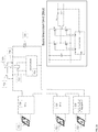
- the system includes one or more photovoltaic panels 502. Power generated by the panels 502 are provided to a photovoltaic inverter and filter combination 506 and provided to a power grid 510.
- a local controller 504 (discussed in detail below) monitors panel and grid voltages and generates control signals to the inverter and filter 506.
- the local controller 504 controls a full bridge inverter, and a communication interface to allow the local controller to communicate with a system controller.
- the full bridge inverter can take energy generated by the PV panel.
- the output of the PV panel can be smoothed by a capacitor.
- the full bridge output is then presented to a low pass filter before it is provided at an output section.
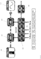
- FIG. 2A shows a stacked phase with a system controller for grid tied application.
- FIG. 2A has a plurality of solar panels 522 providing power to basic inversion units 520.
- the basic inversion units 520 are connected in series, with the output of each basic inversion unit 520 controlled by a system controller 524.
- the output of the series connected basic inversion units 520 is also connected to a resistor 526 in series with switch K1 528.
- the basic inversion units 520 are also connected in series with switch K2 530.
- Switches 528 and 530 could either be solid state switches or relays. Switches 528-530 are controlled by system controller. The output of the switches 528-530 are provided to the grid 534.
- the system can handle a variable number of series connected basic inversion units, where the minimum and maximum number of basic inversion units per system is determined by the aggregate grid voltage across all the series connected full bridge inverters and the maximum and minimum AC output voltage rating of each basic inversion unit.
- Each basic inversion unit can operate as voltage source in order to realize effective basic inversion unit stacking.
- system controller can configure one basic inversion unit as a current source, and the remaining basic inversion units can be used as voltage sources.
- Three separate series connected groups of basic inversion units can be configured as a 3-phase inversion system in one embodiment.
- a system controller includes an outer regulation loop that controls switches K1 and K2 that supply power to the grid.
- the system controller receives communications from basic inversion units over a communication channel.
- the communication channel can be wired such as the power-line communication channel or can be wireless such as Zigbee transceivers, among others.
- the system controller also implements algorithms detecting abnormal grid conditions and methods of disconnecting the stacked basic inversion unit system from the grid by controlling switches K1 and K2.
- FIG. 2B show embodiments of the basic inversion unit of FIG. 1 .
- a solar panel 530 provides direct current (DC) output to a full bridge inverter 532.
- the output of the full bridge inverter 532 is provided to a low pass filer 534 which can be an inductor-capacitor (LC) type filter in one embodiment.
- the output of the filter 534 is provided to an AC power grid or AC power bus.
- the output of the filter 534 is monitored by the local controller 550.
- the system controller 540 monitors output voltage and current of a phase witch stacked basic inversion units, as shown in FIG. 2A .
- the system controller sends commands to a communication module 568 to set parameters of a limiter 558 to adjust the voltage and current generated by the inverter 532.
- the system of FIG. 2B is monitored by an maximum power point tracking (MPPT) module 551 whose details are discussed in FIG. 3 .
- the MPPT module 552 monitors power from the panel 530.
- the MPPT module 551 output is received by a summer 554 that drives a DC voltage controller 556, which can be a proportional integral controller in one embodiment.
- a reference current value is the output of the DC voltage controller.
- the voltage controller 556 output is connected to the limiter 558 to generate an output m, modulation index.
- a multiplier 560 receives the output of the limiter 558 and a phase lock loop (PLL) 570 to generate an output m sin ⁇ .
- the limiter 558 and PLL 570 monitor the grid output as supplied through the low pass filter 534.
- the output of the multiplier 560 is supplied to a driver 572 such as a pulse width modulation (PWM) driver that drives the full bridge inverter 532.
- PWM pulse width modulation
- FIG. 3 shows an exemplary MPPT process.
- the system senses voltage at time k V(k) and current at time k I(k) (580).
- the voltage difference and current difference between the current period and the prior period is determined (582).
- FIG. 4 shows an exemplary current limiting process for the grid voltage.
- the maximum and minimum voltage values are received from system controller (610).
- the system samples inverter output voltage Vom and current lom (612).
- ⁇ is set as Voref - Vom (616) and then m is set to be k1 ⁇ ⁇ + k2 ⁇ ⁇ /s (618).
- the process determines if Vom > Vommax (620). If yes, Voref is set to Vommax and ⁇ is set to Voref - Vom (622) and voltage control limiting loop is run. The process then sets m as k1 ⁇ ⁇ + k2 ⁇ ⁇ /s (624). If no, the regular current loop is run having loref set to Iref and ⁇ is set as Iref - lom (626). Next, m is set to be k3 ⁇ ⁇ + k4 ⁇ ⁇ /s (628).
- the process proceeds to chek acceptable range for modulation index m.
- Limits for m are set to mmin to be Vommin/Vp and mmax to be Vomax/Vp (630).
- FIG. 5 shows an exemplary phase lock loop.
- a single phase voltage (V ⁇ ) and an internally generated signal (V ⁇ ) are used as inputs to a Park transformation block ( ⁇ -dq).
- the d-axis output of the Park transformation is used in a control loop to obtain phase and frequency information of the input signal.
- V ⁇ is obtained through the use of an inverse Park transformation, where the inputs are the d and q-axis outputs of the Park transformation (dq- ⁇ ) fed through first-order pole blocks.
- the poles are used to introduce an energy storage element in the internal feedback loops.
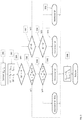
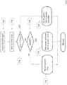
- FIG. 6A shows an exemplary process for controlling the system of FIG. 2A .
- the process determines if the stacked inverter phase voltage, Vgs, is greater than or equal to grid voltage, Vgm (666) and if not, the process waits until the desired voltage is reached. Once this is achieved, the process closes relay or switch K1 (668). This is normal operating mode where power from P panels is being delivered to the AC grid. Next, the process monitors delivered power to the grid, Ps If the power Ps is greater than or equal to the minimum operating power Pmin (670), the process loops back to 670 to continue providing power. If not, the process opens relays K1 and K2 and performs system shutdown (672).
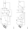
- FIGS. 6B-6D show exemplary basic inversion units that can be used with FIG. 2A .
- FIG. 6B shows an exemplary basic inversion unit comprising a local controller and full bridge inverter with an LC output filter and a DC boost circuit
- FIG. 6C shows an exemplary basic inversion unit comprising a local controller and full bridge inverter with and LC output filter and DC boost circuit and active decoupling filter
- FIG. 6D shows an exemplary basic inversion unit comprising a local controller and full bridge inverter with an LC output filter and push pull DC converter (isolated version).
- the boost converter step-up converter
- the boost converter is a power converter with an output DC voltage greater than its input DC voltage.
- SMPS switching-mode power supply
- the basic principle of a boost converter consists of two distinct states: in the On-state, the switch is closed, resulting in an increase in the inductor current; in the Off-state, the switch is open and the only path offered to inductor current is through the output diode, the capacitor and the load. These results in transferring the energy accumulated during the On-state into the output capacitor.
- the input current is the same as the inductor current, so it is not discontinuous as in the buck converter and the requirements on the input filter are relaxed compared to a buck converter.
- FIG. 7 shows an exemplary off-grid power control application.
- the system controller defines output frequency and operating voltage for each basic inversion unit (690).
- the system controller assigns a master function to one basic inversion unit (692), and the system controller assigns slave function to all other stacked basic inversion units (694).
- the master starts first and provides AC power serving as a reference frequency to slave basic inversion units (696).
- Each slave lock to reference frequency using a PLL and start generating its own AC power (698).
- the system controller monitors power production and adjusts basic inversion unit operation as necessary (699).
- FIG. 8 shows an exemplary master basic inversion unit control process for the off-grid application of FIG. 7 .
- the system sets an input reference voltage Vmref as Vg/n, where n is the number of series connected basic inversion units (710).
- Vmref the input reference voltage
- the process runs a current loop (716) and generates modulation signal based on the loop output and frequency information received from system controller.
- FIG. 9 shows an exemplary slave basic inversion unit control process for the off-grid application of FIG. 7 .
- the system sets an input reference voltage Vmref as Vg/n, where n is the number of series connected basic inversion units (740).
- Vmref the input reference voltage
- the process runs a PLL, locks to the AC frequency, runs a current loop (742) and generates modulation signal based on PLL output and the loop output.
- FIG. 10 shows an exemplary system control process for the off-grid application of FIG. 7 .
- the system sets an input reference voltage Vmref as Vg/n, where n is the number of series connected basic inversion units (760) and defines an output frequency.
- the process sends the reference voltage information and output frequency to the basic inversion units (762).
- the process determines if Vg is equal to Vgref (764). If not, the system checks each basic inversion unit to see if the MPPT is achieved (766). If no basic inversion unit is below MPPT, the process checks the output voltage against a low voltage limit (768). Alternatively, for basic inversion units whose output is below the MPPT, the process increases the target voltage Vm' to these basic inversion units (770). From 764, if Vg is equal to Vgref, the process notifies the system that the set point voltage has been achieved (772).
- the system includes a junction box with two standard cables and connectors.
- Each basic inversion unit provides an output AC power to a series connected AC bus.
- the AC bus terminates into a system controller box.
- the system controller generally connects together the outputs from all the basic inversion units to form a single AC feed to an electric panel.
- the photovoltaic (PV) solar energy receiver or panel can use a plurality of solar cells disposed in a lamination stack on a top surface of a substrate.
- Suitable solar cells may include, for example, conventional single or multi-crystalline silicon solar cells, thin film (e.g., amorphous silicon, cadmium telluride, or copper indium gallium selenide) solar cells, and III-V solar cells.
- FIG. 11 shows an exemplary integrated circuit implementation of a power generation system.
- a photovoltaic (PV) solar energy receiver or panel 100 has a plurality of solar cells disposed in a lamination stack on a top surface of a substrate.
- Suitable solar cells may include, for example, conventional single or multi-crystalline silicon solar cells, thin film (e.g., amorphous silicon, cadmium telluride, or copper indium gallium selenide) solar cells, and III-V solar cells.
- a single string of solar cells can be arranged in a single row, in other variations more or fewer solar cells may be used, and they may be arranged in one, two, or more parallel rows along the substrate.
- two or more PV panels 100 may be positioned end-to-end and electrically and fluidly coupled to provide a larger receiver.
- Each PV panel 100 is coupled to a micro-inverter that converts DC power generated by the PV panel 100 into AC power.
- the micro-inverters of the present invention meter out current that is in-phase with the AC grid current and generate such current with low distortion. This is done using a plurality of integrated circuits.
- the output of the PV panel 100 is regulated by a DC power bridge (DPB) 102, whose output is provided to an AC power bridge (APB) 104.
- the output of APB 104 is provided to an electrical grid 110.
- the DPB 102 and APB 104 are controlled by a chip scale inversion controller (CSIC) 106, which communicates with the system controller through a communication transceiver (CTRX) 108.
- the CTRX 108 can be a powerline communication, a wireless communication such as a Zigbee, or another form of communication
- An electric panel can be used to connect the power from a plurality of series connected basic inversion units through the system controller to the power grid and, in some applications, to appliances within a user's facility.
- the electric panel is a well-known AC distribution hub having various circuit breakers and/or fuses to distribute electricity to various circuits within the home.
- the electric panel is coupled through the electric meter to the power grid. The meter determines the amount of power supplied to the grid, such that the owner of the PV panel can be compensated for supplying electricity.
- the basic inversion units convert DC to AC in accordance with the control and switching signals produced by the controller.
- the controller produces the control and switching signals in response to the samples of the DC and AC signals. Consequently, the basic inversion units may be optimally controlled to utilize a particular mode of operation to correspond to the present state of the DC and AC signals, i.e., to optimally match the AC output to the phase of the power grid such that the AC power is efficiently coupled to the power grid.
- a DC energy source provides input power to the AC bridge.
- a decoupling capacitor filters switching ripple from the AC bridge as well as lower frequency ripple from the AC grid.
- the AC bridge can be a PWM controlled half bridge or full bridge inverter which output terminals are connected to a AC filter.
- the AC filter can be a low pass filter that filters out the high frequency PWM harmonic noise.
- the output circuit implements a sensing circuit for synchronization to the AC grid frequency and a disconnect relay.
- a DC conversion stage may be required to adjust dc bus voltage for optimal performance.
- a boost circuit would be, for example, used to increase the operating voltage across the DC link capacitor thereby allowing for a larger peak to peak AC operating voltage across the AC input and output terminals.
- a larger peak to peak AC operating voltage allows for fewer single level inverters to be used to generate a required stacked phase AC output voltage.
- a buck circuit would be used to reduce the operating voltage across the DC link capacitor. This would enable use of lower voltage rating transistors in the AC bridge thereby increasing amount of power that one stacked phase can produce and in turn reduce system cost.
- DC energy is supplied by a DC electric source which can be a solar panel, a battery, or a vehicular DC generator, among others.
- the output of the DC electric source is provided to a DC stage, whose output is smoothed by a filter and provided to a bridge circuit.
- the output of the bridge circuit is provided to a filter, and the resulting output stage is connected in series to the output of other basic inversion units using suitable cables.
- DC energy is supplied to each basic inversion unit by a PV panel.
- the output of the PV is provided to a boost circuit, whose output is smoothed by capacitor and provided to a full bridge inverter circuit.
- the output of the full bridge inverter circuit is provided to a filter, and the resulting output is series connected to the other basic inversion units using cables.
- the ripple current across the input capacitor has the form of a sine wave at double the line frequency.
- the current from PV panel can be maintained constant and that way maximum power from PV panel can be obtained.
Landscapes
- Engineering & Computer Science (AREA)
- Power Engineering (AREA)
- Inverter Devices (AREA)
- Control Of Electrical Variables (AREA)
Claims (19)
- Mehrfach-Gleichstrom-(DC)-Spannungsquellenwechselrichter zur Stromversorgung eines Wechselstrom-(AC)-Systems, umfassend:eine Vielzahl von Vollbrückenwechselrichtern (520), die jeweils einen Primärknoten und einen Sekundärknoten aufweisen, wobei jeder der Vollbrückenwechselrichter einen positiven und einen negativen Knoten aufweist, wobei jeder der Vollbrückenwechselrichter eine Spannungsunterstützungsvorrichtung, die zwischen dem positiven Knoten und dem negativen Knoten in einer parallelen Beziehung elektrisch geschaltet ist, und eine Gleichstrom-(DC)-Quelle aufweist, die zwischen den positiven und den negativen Knoten geschaltet ist;mindestens eine gestapelte Wechselrichterphase, wobei jede gestapelte Wechselrichterphase eine Vielzahl der Vollbrückenwechselrichter aufweist, wobei jeder der Vollbrückenwechselrichter in jeder gestapelten Wechselrichterphase, die in einer Reihenbeziehung mit dem Sekundärknoten von einem der Vollbrückenwechselrichter verschaltet ist, der mit dem Primärknoten eines anderen Vollbrückenwechselrichters verbunden ist, wobei die Reihenverschaltung einen ersten Vollbrückenwechselrichter und einen letzten Vollbrückenwechselrichter definiert, wobei jede Phase einen Eingangsknoten an dem Primärknoten des ersten Vollbrückenwechselrichters (BIU1) und einen Ausgangsknoten an dem Sekundärknoten des letzten Vollbrückenwechselrichters (BIUn) aufweist;eine lokale Steuerung, die mit jedem Vollbrückenwechselrichter gekoppelt ist, die die Steuersignale an jeden Vollbrückenwechselrichter bereitstellt, um eine annähernd nahezu sinusförmige Spannungswellenform auszugeben, wobei jede lokale Steuerung mit einem Kommunikations-Transceiver gekoppelt ist; undein oder mehrere (Q1, Q2, Q3, Q4) oder Relais, die zwischen dem Primär- und/oder Sekundärleiter jeder gestapelten Wechselrichterphase und dem Stromnetz in Reihe geschaltet sind; undeine Systemsteuerung (524), die dazu ausgelegt ist, mit jedem lokalen Steuerungskommunikations-Transceiver zu kommunizieren; wobei die Systemebenensteuerung dazu ausgelegt ist, ein Systemsteuersignal zur Konfiguration, Aktivierung, Deaktivierung und Betriebsartenauswahl der lokalen Steuerung zu erzeugen, dadurch gekennzeichnet, dassdie Systemsteuerung (524) mindestens zwei parallele Schalter (528, 530) beinhaltet, die zwischen einer gestapelten Wechselrichterphase und dem Netz in Reihe geschaltet sind, wobei jeder der Schalter als Trennvorrichtung der gestapelten Wechselrichterphase und des Netzes dient, wobei mindestens einer der Schalter mit einer Strombegrenzungsvorrichtung (526) in Reihe geschaltet ist; wobei der Schalter einen Leitungsweg bereitstellt, der als ein strombegrenztes Phasenreferenzsignal von einer Wechselstrom-(AC)-Leitungsspannung für eine oder mehrere lokale Steuerungen während der Systeminitialisierung dient;die Systemsteuerung dazu ausgelegt ist, die Anlaufspannung und den Betriebsspannungsbereich für jede Grundinversionseinheit (BIU) zu berechnen und zu kommunizieren;die Systemsteuerung dazu ausgelegt ist, Steuerbefehle zur Aktivierung und Deaktivierung jeder Grundinversionseinheit (BIU) zu bestimmen und zu kommunizieren; unddie Systemsteuerung dazu ausgelegt ist, Steuerbefehle zur Aktivierung und Deaktivierung des gesamten Spannungsquellenwechselrichters zu bestimmen und zu kommunizieren.
- Mehrfach-Gleichstrom-(DC)-Spannungsquellenwechselrichter nach Anspruch 1, der drei gestapelte Wechselrichterphasen umfasst.
- Mehrfach-Gleichstrom-(DC)-Spannungsquellenwechselrichter nach Anspruch 2, der drei gestapelte Phasen umfasst, die in einer Stern-(Y)-Schaltung geschaltet sind.
- Mehrfach-Gleichstrom-(DC)-Spannungsquellenwechselrichter nach Anspruch 2, der drei gestapelte Phasen umfasst, die in einer Dreieck-(Δ)-Schaltung geschaltet sind.
- Mehrfach-Gleichstrom-(DC)-Spannungsquellenwechselrichter nach Anspruch 1, wobei jede Vollbrückenstufe einen Schalter zum Kurzschließen ihres Ausgangs enthält, so dass die gestapelte Phase mit den restlichen in Reihe geschalteten Vollbrücken arbeiten kann.
- Mehrfach-Gleichstrom-(DC)-Spannungsquellenwechselrichter nach Anspruch 1, wobei jeder Vollbrückenwechselrichter Folgendes umfasst:
ein erstes Schaltpaar und ein zweites Schaltpaar, wobei jedes der Schaltpaare eine Vielzahl von Schaltmitteln zum steuerbaren Regeln des elektrischen Stromflusses aufweist, wobei jedes der Schaltmittel ein erstes Ende und ein zweites Ende aufweist, wobei das erste Schaltpaar eine Vielzahl von Schaltmitteln aufweist, die an dem ersten Ende des positiven Knotens des Vollbrückenwechselrichters, dem zweiten Ende eines der Schaltmittel des ersten mit dem Primärknoten elektrisch verbundenen Schaltpaars, dem zweiten Ende eines anderen der Schaltmittel des ersten mit dem Sekundärknoten elektrisch verbundenen Schaltpaars elektrisch verbunden sind, wobei das zweite Schaltpaar eine Vielzahl von Schaltmitteln aufweist, die an den zweiten Enden des negativen Knotens des Vollbrückenwechselrichters, dem ersten Ende eines der Schaltmittel des zweiten mit dem Primärknoten elektrisch verbundenen Schaltpaars, dem ersten Ende eines anderen der Schaltmittel des zweiten mit dem Sekundärknoten elektrisch verbundenen Schaltpaars elektrisch verbunden sind. - Mehrfach-Gleichstrom-(DC)-Spannungsquellenwechselrichter nach Anspruch 1, der einen passiven Tiefpassfilter umfasst, der zwischen Schaltmitteln und Primär- und Sekundärknoten geschaltet ist.
- Mehrfach-Gleichstrom-(DC)-Spannungsquellenwechselrichter nach Anspruch 6, wobei ein Kondensator zwischen den Primär- und den Sekundärknoten zur Synchronisation der Knoten geschaltet ist.
- Mehrfach-Gleichstrom-(DC)-Spannungsquellenwechselrichter nach Anspruch 6, wobei das Schaltpaar eine Gate-Abschaltvorrichtung und eine antiparallele Vorrichtung umfasst, die parallel geschaltet und entgegengesetzt in Bezug aufeinander vorgespannt sind.
- Mehrfach-Gleichstrom-(DC)-Spannungsquellenwechselrichter nach Anspruch 9, wobei die Gate-Abschaltvorrichtung eine Komponente umfasst, die ausgewählt ist aus der Gruppe bestehend aus: einem Gate-Abschaltthyristor, einem isolierten Gate-Bipolartransistor (IGBT), einem Metalloxid-Halbleiter-Feldeffekttransistor (MOSFET), einem Metall-Halbleiter-Feldeffekttransistor (MESFET), einem Sperrschicht-Feldeffekttransistor (JFET), einem MOSFETgesteuerten Thyristor, einem bipolaren Sperrschicht-Transistor (BJT), einem statischen Induktionstransistor, einem statischen Induktionsthyristor und einem MOSFET-Abschaltthyristor, einem Galliumnitrid-(GaN)-Transistor, einem Siliziumkarbid-(SiC)-Transistor.
- Mehrfach-Gleichstrom-(DC)-Spannungsquellenwechselrichter nach Anspruch 9, wobei die antiparallele Vorrichtung eine Diode ist.
- Mehrfach-Gleichstrom-(DC)-Spannungsquellenwechselrichter nach Anspruch 1, der eine Komponente umfasst, die zwischen den positiven und negativen Knoten des Brückenwechselrichters geschaltet ist, wobei die Komponente ausgewählt ist aus der Gruppe bestehend aus: Kondensatoren, Batterien, Brennstoffzellen, Photovoltaikzellen und Biomassezellen.
- Mehrfach-Gleichstrom-(DC)-Spannungsquellenwechselrichter nach Anspruch 1, der eine nicht isolierte getaktete Spannungsregelungsschaltung zwischen der Gleichstromquelle und dem Vollbrückenwechselrichter umfasst.
- Mehrfach-Gleichstrom-(DC)-Spannungsquellenwechselrichter nach Anspruch 1, der eine isolierte getaktete Spannungsregelungsschaltung zwischen der Gleichstromquelle und dem Vollbrückenwechselrichter umfasst.
- Mehrfach-Gleichstrom-(DC)-Spannungsquellenwechselrichter nach Anspruch 1, der einen aktiven Filter zum Entkoppeln der Wechselstrom-(AC)-Modulation umfasst, die der Gleichstrom-(DC)-Spannungsquelle auferlegt wird, wenn sie mit Strombegrenzungs-Gleichstrom-(DC)-Quellen einschließlich Photovoltaikzellen verwendet wird.
- Mehrfach-Gleichstrom-(DC)-Spannungsquellenwechselrichter nach Anspruch 1, der eine variable Anzahl von Vollbrücken zur Konfiguration mit variablen Netzspannungen umfasst.
- Mehrfach-Gleichstrom-(DC)-Spannungsquellenwechselrichter nach Anspruch 1, wobei jede gestapelte Vollbrücke dazu ausgelegt ist, mit unterschiedlicher Leistung zu arbeiten.
- Mehrfach-Gleichstrom-(DC)-Spannungsquellenwechselrichter nach Anspruch 1, der eine variable Anzahl von gestapelten Vollbrücken für jede Phase umfasst.
- Mehrfach-Gleichstrom-(DC)-Spannungsquellenwechselrichter nach Anspruch 1, der eine Systemsteuerung aufweist, die zwei parallele Schalter enthält, die selektiv jede gestapelte Wechselrichterphase mit dem Netz verbinden, wobei mindestens einer der parallelen Schalter mit einer Strombegrenzungsvorrichtung in Reihe geschaltet ist.
Applications Claiming Priority (2)
| Application Number | Priority Date | Filing Date | Title |
|---|---|---|---|
| US13/357,616 US9143056B2 (en) | 2011-12-16 | 2012-01-25 | Stacked voltage source inverter with separate DC sources |
| PCT/US2013/021350 WO2013112304A1 (en) | 2012-01-25 | 2013-01-13 | Stacked voltage source inverter with separate dc sources |
Publications (3)
| Publication Number | Publication Date |
|---|---|
| EP2807737A1 EP2807737A1 (de) | 2014-12-03 |
| EP2807737A4 EP2807737A4 (de) | 2016-04-20 |
| EP2807737B1 true EP2807737B1 (de) | 2019-05-08 |
Family
ID=48874604
Family Applications (1)
| Application Number | Title | Priority Date | Filing Date |
|---|---|---|---|
| EP13741065.0A Active EP2807737B1 (de) | 2012-01-25 | 2013-01-13 | Gestapelter spannungsquellenumrichter mit getrennten gleichstromquellen |
Country Status (8)
| Country | Link |
|---|---|
| US (2) | US9143056B2 (de) |
| EP (1) | EP2807737B1 (de) |
| JP (1) | JP2015510748A (de) |
| KR (1) | KR102139389B1 (de) |
| CN (1) | CN104081647B (de) |
| IN (1) | IN2014KN01375A (de) |
| TW (1) | TWI604686B (de) |
| WO (1) | WO2013112304A1 (de) |
Families Citing this family (66)
| Publication number | Priority date | Publication date | Assignee | Title |
|---|---|---|---|---|
| US9418864B2 (en) | 2008-01-30 | 2016-08-16 | Infineon Technologies Ag | Method of forming a non volatile memory device using wet etching |
| US8842454B2 (en) * | 2010-11-29 | 2014-09-23 | Solarbridge Technologies, Inc. | Inverter array with localized inverter control |
| CN103782471B (zh) | 2011-07-11 | 2017-08-22 | 赛恩沃茨公司 | 用于太阳能光伏能量收集和转换的系统及方法 |
| US9263971B2 (en) * | 2011-12-16 | 2016-02-16 | Empower Micro Systems Inc. | Distributed voltage source inverters |
| US9099938B2 (en) * | 2011-12-16 | 2015-08-04 | Empower Micro Systems | Bi-directional energy converter with multiple DC sources |
| US9143056B2 (en) | 2011-12-16 | 2015-09-22 | Empower Micro Systems, Inc. | Stacked voltage source inverter with separate DC sources |
| US9401663B2 (en) | 2012-12-21 | 2016-07-26 | Infineon Technologies Austria Ag | Power converter circuit with AC output |
| US9478989B2 (en) * | 2012-01-17 | 2016-10-25 | Infineon Technologies Austria Ag | Power converter circuit with AC output |
| US9484746B2 (en) | 2012-01-17 | 2016-11-01 | Infineon Technologies Austria Ag | Power converter circuit with AC output |
| US9425622B2 (en) | 2013-01-08 | 2016-08-23 | Infineon Technologies Austria Ag | Power converter circuit with AC output and at least one transformer |
| US9461474B2 (en) * | 2012-01-17 | 2016-10-04 | Infineon Technologies Austria Ag | Power converter circuit with AC output |
| WO2014047327A1 (en) * | 2012-09-19 | 2014-03-27 | Enphase Energy, Inc. | Serially connected micro-inverter system with trunk and drop cabling |
| EP2717409A1 (de) * | 2012-10-03 | 2014-04-09 | Belenos Clean Power Holding AG | Regulierung eines elektronischen Spannungsanpassungsmoduls |
| DE102012218889A1 (de) * | 2012-10-17 | 2014-04-17 | Robert Bosch Gmbh | Verfahren und Vorrichtung zum Übertragen von elektrischer Leistung |
| US10027114B2 (en) * | 2012-10-25 | 2018-07-17 | Mpowersolar Inc. | Master slave architecture for distributed DC to AC power conversion |
| US9270201B1 (en) * | 2012-10-25 | 2016-02-23 | mPower Solar Inc. | Solar inverter |
| AT513542B1 (de) * | 2012-11-15 | 2014-07-15 | Fronius Int Gmbh | Verfahren und Anordnung zur Datenkommunikation zwischen einem Wechselrichter und einer Netzüberwachungseinheit |
| US9611835B1 (en) | 2013-01-11 | 2017-04-04 | Google Inc. | Motor control topology for airborne power generation and systems using same |
| US9680305B2 (en) * | 2013-03-14 | 2017-06-13 | Hiq Solar, Inc. | Implementation of fire safety shutdown for solar panels with high reliability |
| US9602025B2 (en) * | 2013-07-12 | 2017-03-21 | Infineon Technologies Austria Ag | Multiphase power converter circuit and method |
| FR3009454B1 (fr) * | 2013-07-30 | 2015-09-04 | Commissariat Energie Atomique | Centrale photovoltaique reliee a un reseau electrique haute tension |
| US9294016B2 (en) | 2013-12-19 | 2016-03-22 | Google Inc. | Control methods and systems for motors and generators operating in a stacked configuration |
| DE102013114729B4 (de) * | 2013-12-20 | 2021-09-30 | Sma Solar Technology Ag | Wechselrichter und Verfahren zum Detektieren eines Phasenausfalls in einem Energieversorgungsnetz |
| GB2522201B (en) | 2014-01-15 | 2018-06-27 | Nidec Control Techniques Ltd | Method and system for controlling a power output of an inverter |
| CN104868764B (zh) * | 2014-02-26 | 2017-08-04 | 全汉企业股份有限公司 | 逆变装置及其电源转换方法 |
| WO2015156901A1 (en) * | 2014-04-11 | 2015-10-15 | Kripya LLC | Dual mode micro-inverter system and operation |
| US9590528B2 (en) | 2014-04-11 | 2017-03-07 | Kripya LLC | Dual mode DC-AC inverter system and operation |
| EP2977848B1 (de) * | 2014-07-23 | 2018-02-14 | DET International Holding Limited | Impedanzkompensation |
| US20160063413A1 (en) * | 2014-08-28 | 2016-03-03 | OneRoof Energy, Inc. | Solar electrical system optimizer |
| WO2016036803A1 (en) * | 2014-09-02 | 2016-03-10 | Enphase Energy, Inc. | Method and apparatus for detection of local line phase in a multi-phase power line system |
| US9876442B2 (en) * | 2014-10-10 | 2018-01-23 | The Regents Of The University Of California | Robust single-phase DC/AC inverter for highly varying DC voltages |
| TWI566514B (zh) * | 2015-05-11 | 2017-01-11 | 茂勝開發股份有限公司 | 太陽能發電模組之直流電功率的監測系統及方法 |
| DE102015219338A1 (de) * | 2015-10-07 | 2017-04-13 | Schaeffler Technologies AG & Co. KG | Gleichspannungswandler und Verfahren zum Betrieb eines Gleichspannungswandlers |
| WO2017100827A1 (en) * | 2015-12-14 | 2017-06-22 | Sharp Energy Investments Pty Ltd | Hot water controller |
| GB2597856B (en) * | 2015-12-18 | 2022-07-20 | Southwire Co Llc | Cable integrated solar inverter |
| US10418916B2 (en) * | 2015-12-23 | 2019-09-17 | Daming Zhang | Circuits of voltage source DC/AC converter with LCCL or LCC filter and other modified forms, and operation of microgrid with such circuits |
| US9966890B2 (en) * | 2016-02-16 | 2018-05-08 | Steering Solutions Ip Holding Corporation | Detection of offset errors in phase current measurement for motor control system |
| KR20170124257A (ko) * | 2016-05-02 | 2017-11-10 | 엘지전자 주식회사 | 태양광 모듈 및 이를 구비한 태양광 시스템 |
| CN106253334B (zh) * | 2016-08-19 | 2018-12-28 | 阳光电源股份有限公司 | 一种级联型光伏并网逆变器及其控制方法和控制装置 |
| KR101883558B1 (ko) * | 2016-09-20 | 2018-07-30 | 한국전력공사 | 인버터 기반 독립형 마이크로그리드 내 선로 단락 고장구간 절체 시스템 및 절체 방법 |
| CN106505728B (zh) * | 2016-12-26 | 2023-08-04 | 天津瑞源电气有限公司 | 风电双馈变流器在并网中的供电控制回路 |
| US20180187652A1 (en) * | 2017-01-05 | 2018-07-05 | General Electric Company | Power Converter for Full Conversion Wind Turbine Systems |
| JP7073647B2 (ja) * | 2017-08-07 | 2022-05-24 | オムロン株式会社 | 発電システム |
| EP3500904B1 (de) * | 2017-10-18 | 2019-11-20 | e-peas S.A. | Integrierte schaltung zur energiegewinnung mit synchronisationsmitteln |
| ES2717345A1 (es) * | 2017-12-20 | 2019-06-20 | Power Electronics Espana S L | Convertidor de potencia con puesta en marcha en frio y metodo de puesta en marcha en frio para el convertidor de potencia |
| CN108258954B (zh) * | 2018-03-07 | 2023-10-17 | 重庆润通科技有限公司 | 一种发电机逆变器及逆变发电机 |
| US10714966B2 (en) | 2018-04-18 | 2020-07-14 | Ford Global Technologies, Llc | Isolation switch operation |
| JP7317045B2 (ja) | 2018-04-20 | 2023-07-28 | エーイーエス グローバル ホールディングス, プライベート リミテッド | 高効率発電機ソースインピーダンスの制御のためのシステムおよび方法 |
| US11258444B2 (en) * | 2019-05-17 | 2022-02-22 | Schneider Electric It Corporation | Devices and methods for high-efficiency power switching with cascode GaN |
| CN110401369A (zh) * | 2019-08-12 | 2019-11-01 | 黄山学院 | 高效率高功率密度GaN全桥逆变器模块 |
| WO2021033299A1 (ja) * | 2019-08-22 | 2021-02-25 | 日新電機株式会社 | 電源装置、及び電源装置の制御方法 |
| TWI710207B (zh) * | 2019-08-23 | 2020-11-11 | 日商日新電機股份有限公司 | 電源裝置以及電源裝置的控制方法 |
| US11621667B2 (en) | 2019-09-16 | 2023-04-04 | Michael Allen | Aggregate off the grid power system |
| US11689011B2 (en) * | 2019-09-23 | 2023-06-27 | 1st Step Solar | Methods and systems for electrical system monitoring and/or control |
| CN110611451B (zh) * | 2019-10-09 | 2024-11-22 | 南京工程学院 | 一种基于氮化镓器件的光伏逆变器及其控制方法 |
| CN112721742B (zh) * | 2021-01-27 | 2023-04-18 | 潍柴动力股份有限公司 | 燃料电池的功率控制系统及方法 |
| JP7614911B2 (ja) * | 2021-03-31 | 2025-01-16 | 本田技研工業株式会社 | グリッドシステム、電力授受方法及びコンピュータプログラム |
| CN113300408B (zh) * | 2021-04-30 | 2023-10-27 | 北京天诚同创电气有限公司 | 微电网群同期控制方法和系统 |
| TWI788991B (zh) * | 2021-09-02 | 2023-01-01 | 義守大學 | 換流裝置 |
| CN114448281B (zh) * | 2022-01-25 | 2024-09-20 | 上海空间电源研究所 | 一种抑制共模电流的非隔离型双Buck逆变器拓扑及控制方法 |
| CN115149802B (zh) * | 2022-09-01 | 2022-11-15 | 浙江日风电气股份有限公司 | 一种直流变换器的控制器、直流变换器 |
| FR3143236A1 (fr) * | 2022-12-07 | 2024-06-14 | Commissariat à l'énergie atomique et aux énergies alternatives | Dispositif électronique et procédé de pilotage d’un convertisseur d’énergie électrique, système électronique de conversion et programme d’ordinateur associés |
| CN220342053U (zh) * | 2023-01-12 | 2024-01-12 | 重庆鼎工机电有限公司 | 一种实现串并联功能的发电机控制系统 |
| AU2023437683A1 (en) * | 2023-03-22 | 2025-10-23 | Fluence Energy, Llc | Modular multilevel converters for battery energy storage |
| WO2025034420A1 (en) * | 2023-08-04 | 2025-02-13 | Enphase Energy, Inc. | Microinverters for photovoltaic applications |
| CN119787861B (zh) * | 2024-12-25 | 2025-11-07 | 深圳拓邦股份有限公司 | 一种离网逆变器控制方法、装置及离网逆变器 |
Family Cites Families (32)
| Publication number | Priority date | Publication date | Assignee | Title |
|---|---|---|---|---|
| US4719550A (en) | 1986-09-11 | 1988-01-12 | Liebert Corporation | Uninterruptible power supply with energy conversion and enhancement |
| US5642275A (en) | 1995-09-14 | 1997-06-24 | Lockheed Martin Energy System, Inc. | Multilevel cascade voltage source inverter with seperate DC sources |
| JP3741171B2 (ja) | 1996-06-17 | 2006-02-01 | 株式会社安川電機 | 多重パルス幅変調方式の電力変換装置 |
| JP2000324807A (ja) * | 1999-05-10 | 2000-11-24 | Seiko Instruments Inc | スイッチングレギュレータ |
| US7348760B2 (en) | 2000-09-21 | 2008-03-25 | O2Micro International Limited | Power management topologies |
| AU2002234951A1 (en) * | 2002-03-04 | 2003-09-16 | Josuke Nakata | Power generating system |
| US6969967B2 (en) | 2003-12-12 | 2005-11-29 | Ut-Battelle Llc | Multi-level dc bus inverter for providing sinusoidal and PWM electrical machine voltages |
| US20050139259A1 (en) | 2003-12-30 | 2005-06-30 | Robert Steigerwald | Transformerless power conversion in an inverter for a photovoltaic system |
| US7596008B2 (en) * | 2005-02-25 | 2009-09-29 | Mitsubishi Electric Corporation | Power conversion apparatus |
| KR100734050B1 (ko) * | 2005-12-26 | 2007-06-29 | 현대중공업 주식회사 | 에이치-브릿지 멀티레벨 인버터를 이용한 전동기 피드백제어방법 |
| GB2454389B (en) | 2006-01-13 | 2009-08-26 | Enecsys Ltd | Power conditioning unit |
| KR101205279B1 (ko) | 2006-03-23 | 2012-11-27 | 엔페이즈 에너지, 인코포레이티드 | 직류를 교류로 변환하는 방법 및 장치 |
| US7643319B2 (en) * | 2007-06-22 | 2010-01-05 | General Electric Company | 7-level wye-connected H-bridge converter topology for powering a high-speed electric motor |
| TWI494734B (zh) * | 2008-05-14 | 2015-08-01 | Nat Semiconductor Corp | 在能量產生系統中提供最大功率點追蹤的方法與系統 |
| US8279644B2 (en) | 2008-05-14 | 2012-10-02 | National Semiconductor Corporation | Method and system for providing maximum power point tracking in an energy generating system |
| US7962249B1 (en) * | 2008-05-14 | 2011-06-14 | National Semiconductor Corporation | Method and system for providing central control in an energy generating system |
| JP2009290919A (ja) | 2008-05-27 | 2009-12-10 | Panasonic Corp | 電力変換装置 |
| US8125177B2 (en) | 2008-06-13 | 2012-02-28 | Baker Hughes Incorporated | System and method for adding voltages of power modules in variable frequency drives |
| AU2009298259A1 (en) * | 2008-10-01 | 2010-04-08 | Sunsil A/S | Power generation system and method of operating a power generation system |
| EP2237403A1 (de) | 2009-03-30 | 2010-10-06 | SMA Solar Technology AG | Wechselrichter mit zwei asymmetrischen Brückenschaltungen und einem Freilaufpfad zur Entkopplung von Gleich- und Wechselspannungsseite |
| US8279642B2 (en) * | 2009-07-31 | 2012-10-02 | Solarbridge Technologies, Inc. | Apparatus for converting direct current to alternating current using an active filter to reduce double-frequency ripple power of bus waveform |
| US8089178B2 (en) | 2009-09-09 | 2012-01-03 | Arraypower, Inc. | Three phase power generation from a plurality of direct current sources |
| KR101094002B1 (ko) | 2009-12-16 | 2011-12-15 | 삼성에스디아이 주식회사 | 전원 변환 장치 |
| WO2011078424A1 (ko) | 2009-12-23 | 2011-06-30 | 부경대학교 산학협력단 | 부하의 세그먼테이션을 고려한 풀 브릿지 인버터 및 그 제어방법 |
| US8271599B2 (en) | 2010-01-08 | 2012-09-18 | Tigo Energy, Inc. | Systems and methods for an identification protocol between a local controller and a master controller in a photovoltaic power generation system |
| US20120091817A1 (en) * | 2010-10-18 | 2012-04-19 | Advanced Energy Industries, Inc. | System, method, and apparatus for ac grid connection of series-connected inverters |
| US9118213B2 (en) * | 2010-11-24 | 2015-08-25 | Kohler Co. | Portal for harvesting energy from distributed electrical power sources |
| US8842454B2 (en) * | 2010-11-29 | 2014-09-23 | Solarbridge Technologies, Inc. | Inverter array with localized inverter control |
| GB2483317B (en) | 2011-01-12 | 2012-08-22 | Solaredge Technologies Ltd | Serially connected inverters |
| US9099938B2 (en) * | 2011-12-16 | 2015-08-04 | Empower Micro Systems | Bi-directional energy converter with multiple DC sources |
| US9263971B2 (en) | 2011-12-16 | 2016-02-16 | Empower Micro Systems Inc. | Distributed voltage source inverters |
| US9143056B2 (en) | 2011-12-16 | 2015-09-22 | Empower Micro Systems, Inc. | Stacked voltage source inverter with separate DC sources |
-
2012
- 2012-01-25 US US13/357,616 patent/US9143056B2/en active Active
-
2013
- 2013-01-13 EP EP13741065.0A patent/EP2807737B1/de active Active
- 2013-01-13 IN IN1375KON2014 patent/IN2014KN01375A/en unknown
- 2013-01-13 CN CN201380006787.6A patent/CN104081647B/zh active Active
- 2013-01-13 WO PCT/US2013/021350 patent/WO2013112304A1/en not_active Ceased
- 2013-01-13 KR KR1020147020969A patent/KR102139389B1/ko active Active
- 2013-01-13 JP JP2014554733A patent/JP2015510748A/ja active Pending
- 2013-01-21 TW TW102102230A patent/TWI604686B/zh active
-
2015
- 2015-03-25 US US14/668,962 patent/US9998033B2/en active Active
Non-Patent Citations (1)
| Title |
|---|
| None * |
Also Published As
| Publication number | Publication date |
|---|---|
| TW201338390A (zh) | 2013-09-16 |
| US9998033B2 (en) | 2018-06-12 |
| US9143056B2 (en) | 2015-09-22 |
| KR20140119710A (ko) | 2014-10-10 |
| EP2807737A4 (de) | 2016-04-20 |
| EP2807737A1 (de) | 2014-12-03 |
| JP2015510748A (ja) | 2015-04-09 |
| TWI604686B (zh) | 2017-11-01 |
| US20130155735A1 (en) | 2013-06-20 |
| CN104081647B (zh) | 2019-08-13 |
| IN2014KN01375A (de) | 2015-10-16 |
| KR102139389B1 (ko) | 2020-08-12 |
| CN104081647A (zh) | 2014-10-01 |
| US20150303829A1 (en) | 2015-10-22 |
| WO2013112304A1 (en) | 2013-08-01 |
Similar Documents
| Publication | Publication Date | Title |
|---|---|---|
| EP2807737B1 (de) | Gestapelter spannungsquellenumrichter mit getrennten gleichstromquellen | |
| US10707782B2 (en) | Bi-directional energy converter with multiple DC sources | |
| US10998833B2 (en) | Distributed voltage source inverters | |
| EP3496258B1 (de) | Sicherheitsmechanismus in verteilten strominstallationen | |
| US9673732B2 (en) | Power converter circuit | |
| CN103782471B (zh) | 用于太阳能光伏能量收集和转换的系统及方法 | |
| US9866144B2 (en) | Three port converter with dual independent maximum power point tracking and dual operating modes | |
| US20170222542A1 (en) | Safety mechanisms, wake up and shutdown methods in distributed power installations | |
| US20130328403A1 (en) | Distributed Substring Architecture for Maximum Power Point Tracking of Energy Sources | |
| Kouro et al. | Photovoltaic energy conversion systems | |
| WO2013098844A2 (en) | Grid tie inverter | |
| Narváez et al. | Design, Sizing And Simulation Of A Hybrid Ac-Dc Microgrid For Improving Energy Efficiency In Residential Applications | |
| Townsend et al. | Capacitance minimisation & alleviation of per-phase power imbalances in cascaded PV converters |
Legal Events
| Date | Code | Title | Description |
|---|---|---|---|
| TPAC | Observations filed by third parties |
Free format text: ORIGINAL CODE: EPIDOSNTIPA |
|
| PUAI | Public reference made under article 153(3) epc to a published international application that has entered the european phase |
Free format text: ORIGINAL CODE: 0009012 |
|
| 17P | Request for examination filed |
Effective date: 20140708 |
|
| AK | Designated contracting states |
Kind code of ref document: A1 Designated state(s): AL AT BE BG CH CY CZ DE DK EE ES FI FR GB GR HR HU IE IS IT LI LT LU LV MC MK MT NL NO PL PT RO RS SE SI SK SM TR |
|
| DAX | Request for extension of the european patent (deleted) | ||
| RA4 | Supplementary search report drawn up and despatched (corrected) |
Effective date: 20160323 |
|
| RIC1 | Information provided on ipc code assigned before grant |
Ipc: H02M 7/49 20070101ALI20160317BHEP Ipc: H02J 3/38 20060101ALI20160317BHEP Ipc: H02M 7/48 20070101AFI20160317BHEP Ipc: H02J 3/32 20060101ALI20160317BHEP |
|
| STAA | Information on the status of an ep patent application or granted ep patent |
Free format text: STATUS: REQUEST FOR EXAMINATION WAS MADE |
|
| GRAP | Despatch of communication of intention to grant a patent |
Free format text: ORIGINAL CODE: EPIDOSNIGR1 |
|
| STAA | Information on the status of an ep patent application or granted ep patent |
Free format text: STATUS: GRANT OF PATENT IS INTENDED |
|
| INTG | Intention to grant announced |
Effective date: 20180919 |
|
| GRAS | Grant fee paid |
Free format text: ORIGINAL CODE: EPIDOSNIGR3 |
|
| GRAA | (expected) grant |
Free format text: ORIGINAL CODE: 0009210 |
|
| STAA | Information on the status of an ep patent application or granted ep patent |
Free format text: STATUS: THE PATENT HAS BEEN GRANTED |
|
| AK | Designated contracting states |
Kind code of ref document: B1 Designated state(s): AL AT BE BG CH CY CZ DE DK EE ES FI FR GB GR HR HU IE IS IT LI LT LU LV MC MK MT NL NO PL PT RO RS SE SI SK SM TR |
|
| RAP1 | Party data changed (applicant data changed or rights of an application transferred) |
Owner name: SUNGROW POWER SUPPLY CO., LTD. |
|
| REG | Reference to a national code |
Ref country code: GB Ref legal event code: FG4D |
|
| REG | Reference to a national code |
Ref country code: CH Ref legal event code: EP Ref country code: AT Ref legal event code: REF Ref document number: 1131767 Country of ref document: AT Kind code of ref document: T Effective date: 20190515 |
|
| REG | Reference to a national code |
Ref country code: DE Ref legal event code: R096 Ref document number: 602013055020 Country of ref document: DE Ref country code: IE Ref legal event code: FG4D |
|
| REG | Reference to a national code |
Ref country code: NL Ref legal event code: FP |
|
| REG | Reference to a national code |
Ref country code: LT Ref legal event code: MG4D |
|
| PG25 | Lapsed in a contracting state [announced via postgrant information from national office to epo] |
Ref country code: SE Free format text: LAPSE BECAUSE OF FAILURE TO SUBMIT A TRANSLATION OF THE DESCRIPTION OR TO PAY THE FEE WITHIN THE PRESCRIBED TIME-LIMIT Effective date: 20190508 Ref country code: HR Free format text: LAPSE BECAUSE OF FAILURE TO SUBMIT A TRANSLATION OF THE DESCRIPTION OR TO PAY THE FEE WITHIN THE PRESCRIBED TIME-LIMIT Effective date: 20190508 Ref country code: LT Free format text: LAPSE BECAUSE OF FAILURE TO SUBMIT A TRANSLATION OF THE DESCRIPTION OR TO PAY THE FEE WITHIN THE PRESCRIBED TIME-LIMIT Effective date: 20190508 Ref country code: ES Free format text: LAPSE BECAUSE OF FAILURE TO SUBMIT A TRANSLATION OF THE DESCRIPTION OR TO PAY THE FEE WITHIN THE PRESCRIBED TIME-LIMIT Effective date: 20190508 Ref country code: AL Free format text: LAPSE BECAUSE OF FAILURE TO SUBMIT A TRANSLATION OF THE DESCRIPTION OR TO PAY THE FEE WITHIN THE PRESCRIBED TIME-LIMIT Effective date: 20190508 Ref country code: PT Free format text: LAPSE BECAUSE OF FAILURE TO SUBMIT A TRANSLATION OF THE DESCRIPTION OR TO PAY THE FEE WITHIN THE PRESCRIBED TIME-LIMIT Effective date: 20190908 Ref country code: NO Free format text: LAPSE BECAUSE OF FAILURE TO SUBMIT A TRANSLATION OF THE DESCRIPTION OR TO PAY THE FEE WITHIN THE PRESCRIBED TIME-LIMIT Effective date: 20190808 Ref country code: FI Free format text: LAPSE BECAUSE OF FAILURE TO SUBMIT A TRANSLATION OF THE DESCRIPTION OR TO PAY THE FEE WITHIN THE PRESCRIBED TIME-LIMIT Effective date: 20190508 |
|
| PG25 | Lapsed in a contracting state [announced via postgrant information from national office to epo] |
Ref country code: GR Free format text: LAPSE BECAUSE OF FAILURE TO SUBMIT A TRANSLATION OF THE DESCRIPTION OR TO PAY THE FEE WITHIN THE PRESCRIBED TIME-LIMIT Effective date: 20190809 Ref country code: BG Free format text: LAPSE BECAUSE OF FAILURE TO SUBMIT A TRANSLATION OF THE DESCRIPTION OR TO PAY THE FEE WITHIN THE PRESCRIBED TIME-LIMIT Effective date: 20190808 Ref country code: LV Free format text: LAPSE BECAUSE OF FAILURE TO SUBMIT A TRANSLATION OF THE DESCRIPTION OR TO PAY THE FEE WITHIN THE PRESCRIBED TIME-LIMIT Effective date: 20190508 Ref country code: RS Free format text: LAPSE BECAUSE OF FAILURE TO SUBMIT A TRANSLATION OF THE DESCRIPTION OR TO PAY THE FEE WITHIN THE PRESCRIBED TIME-LIMIT Effective date: 20190508 |
|
| PG25 | Lapsed in a contracting state [announced via postgrant information from national office to epo] |
Ref country code: DK Free format text: LAPSE BECAUSE OF FAILURE TO SUBMIT A TRANSLATION OF THE DESCRIPTION OR TO PAY THE FEE WITHIN THE PRESCRIBED TIME-LIMIT Effective date: 20190508 Ref country code: SK Free format text: LAPSE BECAUSE OF FAILURE TO SUBMIT A TRANSLATION OF THE DESCRIPTION OR TO PAY THE FEE WITHIN THE PRESCRIBED TIME-LIMIT Effective date: 20190508 Ref country code: RO Free format text: LAPSE BECAUSE OF FAILURE TO SUBMIT A TRANSLATION OF THE DESCRIPTION OR TO PAY THE FEE WITHIN THE PRESCRIBED TIME-LIMIT Effective date: 20190508 Ref country code: CZ Free format text: LAPSE BECAUSE OF FAILURE TO SUBMIT A TRANSLATION OF THE DESCRIPTION OR TO PAY THE FEE WITHIN THE PRESCRIBED TIME-LIMIT Effective date: 20190508 Ref country code: EE Free format text: LAPSE BECAUSE OF FAILURE TO SUBMIT A TRANSLATION OF THE DESCRIPTION OR TO PAY THE FEE WITHIN THE PRESCRIBED TIME-LIMIT Effective date: 20190508 |
|
| REG | Reference to a national code |
Ref country code: DE Ref legal event code: R097 Ref document number: 602013055020 Country of ref document: DE |
|
| PG25 | Lapsed in a contracting state [announced via postgrant information from national office to epo] |
Ref country code: SM Free format text: LAPSE BECAUSE OF FAILURE TO SUBMIT A TRANSLATION OF THE DESCRIPTION OR TO PAY THE FEE WITHIN THE PRESCRIBED TIME-LIMIT Effective date: 20190508 |
|
| PLBE | No opposition filed within time limit |
Free format text: ORIGINAL CODE: 0009261 |
|
| STAA | Information on the status of an ep patent application or granted ep patent |
Free format text: STATUS: NO OPPOSITION FILED WITHIN TIME LIMIT |
|
| PG25 | Lapsed in a contracting state [announced via postgrant information from national office to epo] |
Ref country code: TR Free format text: LAPSE BECAUSE OF FAILURE TO SUBMIT A TRANSLATION OF THE DESCRIPTION OR TO PAY THE FEE WITHIN THE PRESCRIBED TIME-LIMIT Effective date: 20190508 |
|
| 26N | No opposition filed |
Effective date: 20200211 |
|
| PG25 | Lapsed in a contracting state [announced via postgrant information from national office to epo] |
Ref country code: PL Free format text: LAPSE BECAUSE OF FAILURE TO SUBMIT A TRANSLATION OF THE DESCRIPTION OR TO PAY THE FEE WITHIN THE PRESCRIBED TIME-LIMIT Effective date: 20190508 |
|
| PG25 | Lapsed in a contracting state [announced via postgrant information from national office to epo] |
Ref country code: SI Free format text: LAPSE BECAUSE OF FAILURE TO SUBMIT A TRANSLATION OF THE DESCRIPTION OR TO PAY THE FEE WITHIN THE PRESCRIBED TIME-LIMIT Effective date: 20190508 |
|
| PG25 | Lapsed in a contracting state [announced via postgrant information from national office to epo] |
Ref country code: MC Free format text: LAPSE BECAUSE OF FAILURE TO SUBMIT A TRANSLATION OF THE DESCRIPTION OR TO PAY THE FEE WITHIN THE PRESCRIBED TIME-LIMIT Effective date: 20190508 |
|
| REG | Reference to a national code |
Ref country code: CH Ref legal event code: PL |
|
| PG25 | Lapsed in a contracting state [announced via postgrant information from national office to epo] |
Ref country code: CH Free format text: LAPSE BECAUSE OF NON-PAYMENT OF DUE FEES Effective date: 20200131 Ref country code: LI Free format text: LAPSE BECAUSE OF NON-PAYMENT OF DUE FEES Effective date: 20200131 |
|
| PG25 | Lapsed in a contracting state [announced via postgrant information from national office to epo] |
Ref country code: IE Free format text: LAPSE BECAUSE OF NON-PAYMENT OF DUE FEES Effective date: 20200113 |
|
| REG | Reference to a national code |
Ref country code: AT Ref legal event code: UEP Ref document number: 1131767 Country of ref document: AT Kind code of ref document: T Effective date: 20190508 |
|
| REG | Reference to a national code |
Ref country code: DE Ref legal event code: R082 Ref document number: 602013055020 Country of ref document: DE Representative=s name: ZACCO LEGAL RECHTSANWALTSGESELLSCHAFT MBH, DE |
|
| PG25 | Lapsed in a contracting state [announced via postgrant information from national office to epo] |
Ref country code: MT Free format text: LAPSE BECAUSE OF FAILURE TO SUBMIT A TRANSLATION OF THE DESCRIPTION OR TO PAY THE FEE WITHIN THE PRESCRIBED TIME-LIMIT Effective date: 20190508 Ref country code: CY Free format text: LAPSE BECAUSE OF FAILURE TO SUBMIT A TRANSLATION OF THE DESCRIPTION OR TO PAY THE FEE WITHIN THE PRESCRIBED TIME-LIMIT Effective date: 20190508 |
|
| PG25 | Lapsed in a contracting state [announced via postgrant information from national office to epo] |
Ref country code: MK Free format text: LAPSE BECAUSE OF FAILURE TO SUBMIT A TRANSLATION OF THE DESCRIPTION OR TO PAY THE FEE WITHIN THE PRESCRIBED TIME-LIMIT Effective date: 20190508 Ref country code: IS Free format text: LAPSE BECAUSE OF FAILURE TO SUBMIT A TRANSLATION OF THE DESCRIPTION OR TO PAY THE FEE WITHIN THE PRESCRIBED TIME-LIMIT Effective date: 20190908 |
|
| REG | Reference to a national code |
Ref country code: DE Ref legal event code: R082 Ref document number: 602013055020 Country of ref document: DE |
|
| PGFP | Annual fee paid to national office [announced via postgrant information from national office to epo] |
Ref country code: NL Payment date: 20260127 Year of fee payment: 14 Ref country code: LU Payment date: 20260127 Year of fee payment: 14 |
|
| PGFP | Annual fee paid to national office [announced via postgrant information from national office to epo] |
Ref country code: GB Payment date: 20260219 Year of fee payment: 14 |
|
| PGFP | Annual fee paid to national office [announced via postgrant information from national office to epo] |
Ref country code: DE Payment date: 20260206 Year of fee payment: 14 |
|
| PGFP | Annual fee paid to national office [announced via postgrant information from national office to epo] |
Ref country code: AT Payment date: 20260120 Year of fee payment: 14 |
|
| PGFP | Annual fee paid to national office [announced via postgrant information from national office to epo] |
Ref country code: BE Payment date: 20260130 Year of fee payment: 14 Ref country code: IT Payment date: 20260108 Year of fee payment: 14 |
|
| PGFP | Annual fee paid to national office [announced via postgrant information from national office to epo] |
Ref country code: FR Payment date: 20260130 Year of fee payment: 14 |