EP2808096A1 - Appareil et procédé de séparation - Google Patents
Appareil et procédé de séparation Download PDFInfo
- Publication number
- EP2808096A1 EP2808096A1 EP14169184.0A EP14169184A EP2808096A1 EP 2808096 A1 EP2808096 A1 EP 2808096A1 EP 14169184 A EP14169184 A EP 14169184A EP 2808096 A1 EP2808096 A1 EP 2808096A1
- Authority
- EP
- European Patent Office
- Prior art keywords
- separation
- distinguishing
- targets
- constituent
- constituent substance
- Prior art date
- Legal status (The legal status is an assumption and is not a legal conclusion. Google has not performed a legal analysis and makes no representation as to the accuracy of the status listed.)
- Granted
Links
Images


Classifications
-
- B—PERFORMING OPERATIONS; TRANSPORTING
- B07—SEPARATING SOLIDS FROM SOLIDS; SORTING
- B07C—POSTAL SORTING; SORTING INDIVIDUAL ARTICLES, OR BULK MATERIAL FIT TO BE SORTED PIECE-MEAL, e.g. BY PICKING
- B07C5/00—Sorting according to a characteristic or feature of the articles or material being sorted, e.g. by control effected by devices which detect or measure such characteristic or feature; Sorting by manually actuated devices, e.g. switches
- B07C5/36—Sorting apparatus characterised by the means used for distribution
- B07C5/363—Sorting apparatus characterised by the means used for distribution by means of air
- B07C5/367—Sorting apparatus characterised by the means used for distribution by means of air using a plurality of separation means
- B07C5/368—Sorting apparatus characterised by the means used for distribution by means of air using a plurality of separation means actuated independently
Definitions
- the present invention relates to a separation apparatus and a separation method for separating small pieces consisting of a specific constituent substance from a group of the small pieces in which plural small pieces obtained by crushing the used household electric appliances and the like are mixed.
- the unneeded household electric appliances become small pieces by crushing and then these crushed small pieces are separated for the constituent substance by using magnetism, wind, oscillation, and the like in household electric appliance-recycling plants, so as to reuse them.
- the high recycling rate is realized because these small pieces are separated for the constituent substance such as iron, copper, aluminum and the like at high purity by using a specific gravity separation device or a magnetism separation device.
- polypropylene which has a low specific gravity, is separated from a component having a high specific gravity through specific gravity segregation using water and thus recovered with a relatively high degree of purity.
- PS polystyrene
- ABS acrylonitrile-butadiene-styrene
- the separation apparatus which can separate the resin materials at high accuracy by using a jet of air and is useful for the recycling of the resin materials, has been known (see, for example, Japanese Patent Laid-Open No. 2009-279553 ).
- FIG. 5 is a schematic side view of the conventional separation apparatus 100.
- the constituent substance of the resin small piece 101 conveyed by the conveyor 104 is distinguished by the distinguishing device 106 when the resin small piece 101 passes the front of the distinguishing device 106.
- the inventors of the present invention have noticed that the conventional separation apparatus 100 cannot separate the resin small pieces 101 at accuracy high enough.
- the cause is that the air is jetted from the jetting nozzle 110, when constant time which is decided uniformly passes after the resin small piece 101 passes through a detection position of the passing detection sensor 111.
- the shapes and sizes of the resin small pieces 101 are various.
- the size of the resin small piece 101 is large for the detection resolution (the minimum size of the detectable resin small piece) of the passing detection sensor 111, plural detection positions exist for the single resin small piece 101. Therefore, plural detection results corresponding to the plural detection positions, respectively, can be obtained with respect to the single resin small piece 101.
- the resin small piece 101 which should be separated may not be blown off successfully, because a posture of the resin small piece 101 is changed by rotation due to the shape and size of the resin small piece 101.
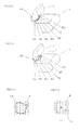
- Fig. 6(a) is a schematic perspective view of the other conventional separation apparatus 150.
- Figs. 6(b) and 6(c) are explanation views of plural distinguishing results (hereinafter referred to as the group of distinguishing results) by the distinguishing device 3 of the other conventional separation apparatus 150.
- a small piece 2A as a separation target is conveyed by the conveyor 1, and the constituent substance of the small piece 2A is distinguished when the small piece 2A passes under the distinguishing device 3.
- the plural distinguishing results 9 denoted by black round marks are distinguishing results of the constituent substances distinguished at a constant interval when the small piece 2A passes under the distinguishing device 3, and the group of distinguishing results is formed by the plural distinguishing results 9. Further, these positions of the black round marks denote the distinguishing positions on the small piece 2A.
- the small piece 2A which is conveyed in a conveying direction X (see Fig. 6(a) ) by the conveyor 1 is thrown out the conveying end portion 4 of the conveyor 1 and flies.
- the group of nozzles 5 provided in order to separate the small piece 2A, which is made from the specific constituent substance, from the flying path of the small piece 2B made from the other constituent substance is allowed to jet air according to the distinguishing results 9, and the small piece 2A made from the specific constituent substance is shot down into the side near the conveyor 1 with reference to the separation board 7, so as to be separated from the small piece 2B made from the other constituent substance.
- the air jetted from the group of nozzles 5 hits only an edge part 2A1 of the board-shaped small piece 2A, because the air is jetted from the group of nozzles 5, based on the distinguishing results 9 (that is, the distinguishing results 9 located in the right end in Fig. 6(b) ) obtained at the first timing in the group of the distinguishing results for the small piece 2A obtained by the distinguishing device 3.
- the air is jetted continuously or intermittently based on the other distinguishing results 9 in the group of the distinguishing results, however, the air from the group of nozzles 5 does not hit the small piece 2A correctly, because the posture of the small piece 2A has been changed already.
- the small piece 2A which should be shot down into the side near the conveyor 1 with reference to the separation board 7, is not shot down into the side, flies the course denoted by the arrow, and falls to a place distant from the conveyor 1 with reference to the separation board 7 as shown in Fig. 6(a) .
- the distinguishing result 9B which should be the same as the distinguishing result 9A may be obtained as a distinguishing result which is different from the distinguishing result 9A by the erroneous decision due to an electric noise or a shape of material.
- the distinguishing result 9A denotes a correct distinguishing result
- the distinguishing result 9B denotes an incorrect distinguishing result.
- the air is jetted based on the incorrect distinguishing result 9B. Therefore, the small piece 2A, which should be separated from the small piece 2B made from the other constituent substance, is not separated correctly, and as a result, the small piece 2A made from the specific constituent substance, which should be separated, is mixed in the group of the small piece 2B made from the other constituent substance.
- An object of the present invention is, in view of the above-mentioned conventional problems, to provide a separation apparatus and a separation method, which can recover the separation target at higher accuracy.
- the 1 st aspect of the present invention is a separation apparatus which analyzes constituent substances of separation targets and recovers the separation target having a predetermined constituent substance, and the separation apparatus characterized by comprising:
- the 2 nd aspect of the present invention is the separation apparatus according to the 1 st aspect of the present invention, wherein the distinguishing unit (3) has lattice-like plural distinguishing points at a predetermined position for the conveying unit (1), distinguishes whether the separation targets (2A, 2B, 2C, 2D) exist or not every each the distinguishing point, and analyzes the constituent substances of the separation targets (2A, 2B, 2C, 2D) every each the distinguishing point when the separation targets (2A, 2B, 2C, 2D) exist, and the recovering unit (5, 6) distinguishes shape, size and position of the separation targets (2A, 2B, 2C, 2D) by analyzing an adjacency state of the distinguishing points where the separation targets (2A, 2B, 2C, 2D) exist, and specifies the separation target (2A) having the predetermined constituent substance (A), to which the air or gas is to be jetted, based on a score which is given to each of the plural kinds of constituent substances (A, B).
- the 3 rd aspect of the present invention is the separation apparatus according to the 1 st aspect of the present invention, wherein
- the distinguishing unit (3) has lattice-like plural distinguishing points at a predetermined position for the conveying unit (1), distinguishes whether the separation targets (2A, 2B, 2C, 2D) exist or not every each the distinguishing point, and analyzes the constituent substances of the separation targets (2A, 2B, 2C, 2D) every each the distinguishing point when the separation targets (2A, 2B, 2C, 2D) exist, and the recovering unit (5, 6) distinguishes the shape, the size and the position of the separation target (2A) having the predetermined constituent substance by analyzing an adjacency state of the distinguishing points where the constituent substances of the separation targets (2A, 2B, 2C, 2D) are the same.
- the 4 th aspect of the present invention is the separation apparatus according to the 1 st aspect of the present invention, wherein the distinguishing unit (3) has lattice-like plural distinguishing points at a predetermined position for the conveying unit (1), distinguishes whether the separation targets (2A, 2B, 2C, 2D) exist or not every each the distinguishing point, and analyzes the constituent substances of the separation targets (2A, 2B, 2C, 2D) every each the distinguishing point when the separation targets (2A, 2B, 2C, 2D) exist, and the recovering unit (5, 6) distinguishes shape, size and position of the separation targets (2A, 2B, 2C, 2D) by analyzing an adjacency state of the distinguishing points where the separation targets (2A, 2B, 2C, 2D) exist, and specifies the separation target (2A) having the predetermined constituent substance (A), to which the air or gas is to be jetted, based on the constituent substance (A, B) of each separation target (2A, 2B, 2C, 2D) on
- the 5 th aspect of the present invention is the separation apparatus according to any one of the 1 st to 4 th aspects of the present inventions, wherein the recovering unit (5, 6) jets the air or gas to a circumference of the center of gravity (11) of the separation target (2A) having the predetermined constituent substance (A) as well as the center of gravity (11).
- the 6 th aspect of the present invention is a separation method of analyzing constituent substances of the separation targets and recovering the separation target having a predetermined constituent substance, and the separation method characterized by comprising steps of:
- FIG. 1 A configuration and operation of a separation apparatus 200 according to the present Embodiment 1 will be described, mainly referring to Figs. 1(a) to 1(c) and Fig. 2 .
- Figs. 1(a), 1(b) and 1(c) are schematic side views of a separation apparatus 200 according to the present Embodiment 1 of the present invention.
- Fig. 2 is a schematic plan view of the separation apparatus 200 according to the present Embodiment 1 of the present invention.
- Embodiment is merely one example of the present invention, and the present invention is not limited to the Embodiment.
- the constituent substances of small pieces 2A, 2B, 2C and 2D are analyzed by a distinguishing device 3 having an optical device which analyzes the constituent substances of the small pieces 2A to 2D, based on the distributions of intensity of reflected light which are detected by irradiating the small pieces 2A to 2D with light, it is possible to separate the small pieces 2A to 2D consisting of the resin material, which cannot be separated by the conventional specific gravity separation device.
- the optical device of the distinguishing device 3 has plural light emitting/light receiving elements (not shown) which are disposed in the direction perpendicular to the conveyance direction X of the conveyor 1 (see Fig. 2 ).
- the conveyor 1 is allowed to have another distribution of intensity of reflected light that is different from each of the unique distributions of intensity of reflected light of the resin materials, it becomes possible to distinguish whether the small pieces 2A to 2D exist or not and analyze the constituent substances thereof as described below.
- the distinguishing device 3 analyzes the constituent substances of the small pieces 2A to 2D as the separation targets which are conveyed by the conveyor 1, and the analyzed small piece 2A made from the specific constituent substance is separated from the flying paths of the other small pieces 2B to 2D which are thrown out the conveying end portion 4 of the conveyor 1.
- the separation apparatus 200 specifies the small piece 2A which should be separated, based on information about the constituent substances analyzed by the distinguishing device 3, determines the timing at which air is allowed to jet pulsingly from nozzles which are disposed above or below the flying path, and blows off the small piece 2A made from the specific constituent substance by jetting the air pulsingly based on the timing in order to separate the small piece 2A from the other small pieces 2B to 2D.
- the air is jetted at least to a position of a center of gravity of the small piece 2A.
- the small pieces 2A, 2B, 2C and 2D denote the small pieces before passing under the distinguishing device 3
- the small pieces 2A', 2B', 2C' and 2D' denote the small pieces after passing under the distinguishing device 3.
- the small pieces 2A' to 2D' are the same as the small pieces 2A to 2D, respectively.
- a group of nozzles 5 is provided with plural nozzles which jet air in order to separate the small piece 2A made from the specific constituent substance from the flying path of the small pieces 2A to 2D as separation targets which are conveyed and are thrown out the conveying end portion 4 of the conveyor 1, and the plural nozzles are disposed in a width direction of the conveyor 1.
- a calculation part 6 specifies the small piece 2A which should be separated, based on information about the constituent substances analyzed by the distinguishing device 3, and determines the timing at which the air is allowed to jet pulsingly from the group of nozzles 5.
- a separation board 7 is a member which is disposed so as to separate the small piece 2A made from the specific constituent substance, which has been separated from the flying paths of the other small pieces 2B to 2D.
- Each size of the small pieces 2A to 2D is about 10 to 100 mm with respect to a lengthwise direction and a lateral direction, and is about 0.5 to 2 mm with respect to a thickness direction.
- a conveyance speed of the conveyor 1 is about 2 to 3 m/sec.
- the interval between the nozzles of the group of nozzles 5, which are disposed in the direction perpendicular to the conveyance direction X of the conveyor 1, is about 5 to 10 mm.
- the distinguishing device 3 distinguishes whether the small piece 2A' as one of the separation targets, which passed under the distinguishing device 3, exists or not, and analyzes the constituent substance of the small piece 2A' when the distinguishing device 3 judges that the small piece 2A' exists.
- the small piece 2A' made from the specific constituent substance, which should be separated, is blown off and separated from the flying paths of the other small pieces 2B' to 2D'.
- the typical flying paths of the small pieces 2B' to 2D' which have been thrown out the conveying end portion 4 of the conveyor 1 are indicated by a solid line, a dotted line and a chain line.
- the distinguishing device 3 distinguishes whether the small pieces 2A to 2D exist or not and analyzes the constituent substances thereof.
- the distinguishing device 3 distinguishes whether the small pieces 2A to 2D exist or not and analyzes the constituent substances thereof at a constant cycle or a constant interval with respect to the parallel and perpendicular directions with reference to the conveyance direction X of the conveyor 1.
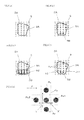
- Fig. 3(a) and Fig. 3(b) are schematic perspective views of the separation apparatus 200 according to Embodiment of the present invention.
- Fig. 3(c) and Fig. 3(d) are explanation views of the groups of distinguishing results by the distinguishing device 3 of the separation apparatus 200 according to Embodiment of the present invention.
- the distinguishing positions 8A, 8B, 8C, 8D, 8E, 8F and 8G denote the positions where the distinguishing device 3 distinguishes whether the small pieces exist or not and analyzes the constituent substances thereof by using the plural light emitting/light receiving elements which the distinguishing device 3 is provided with.
- the distinguishing device 3 has the plural light emitting/light receiving elements as an optical device disposed one-dimensionally, which correspond to the distinguishing positions 8A to 8G, and repeats the distinguishing operation with respect to the conveyance direction X of the conveyor 1.
- the lattice-like plural distinguishing results 9 which are arranged two-dimensionally for the conveyor 1 are obtained.
- the distinguishing device 3 may have an optical device which, for example, has plural light emitting/light receiving elements arranged two-dimensionally, and may collectively obtain many distinguishing results arranged two-dimensionally.
- the calculation part 6 judges that the small piece 2A exists as a single lump on a figure which is formed by the distinguishing positions 8A to 8G.
- the calculation part 6 analyzes an adjacency state of the plural distinguishing results 9, and judges that the plural distinguishing results 9, which correspond to the distinguishing positions on the same figure, are the distinguishing results that should be dealt with as distinguishing results with respect to the single small piece 2A.
- the adjacency state of the plural distinguishing results 9 is analyzed by the calculation part 6, the adjacency state is analyzed by distinguishing whether the small piece exists or not at the distinguishing positions 8A to 8G without taking the constituent substance of the small piece into consideration.
- calculation part 6 judges that the small piece 2A which should be blown off and be separated exists on the figure described above, the calculation part 6 performs quadrature and calculates the position of the center of gravity of the figure.
- a solid line 10 which encloses plural distinguishing results 9 is created, the quadrature is performed for the figure which is formed by the solid line 10 and considered the shape of the small piece 2A, and the position of the center of gravity 11 of the figure is calculated.
- one nozzle that is the nearest to the position of the center of gravity 11 may be used as the corresponding nozzle, or two or more nozzles around the position of the center of gravity 11 may be used as the corresponding nozzles, according to the size of the small piece 2A.
- the length of an air injection period may be adjusted according to the size of the small piece 2A. More concretely, when the weight of the small piece 2A and/or the conveyance speed of the conveyor 1 are large, the air may be jetted not only at the timing when the center of gravity 11 passes under the group of nozzles 5 but also continually or intermittently at least until the center of gravity 11 passes under the group of nozzles 5 from the upper stream side of the position of the group of nozzles 5.
- the small piece 2A can be separated correctly from the small pieces 2B to 2D, because the air also hits a front side portion of the small piece 2A, which is away from the center of gravity 11 by a desired distance with respect to the conveyance direction X of the conveyor 1.
- the optical device since the optical device is used in the distinguishing device 3, the erroneous decision due to the shape of the material, the surface condition of the material, and the like may occur.
- the distinguishing results 9 which show that PS exists in the small piece 2B of PP are obtained. If the air is jetted according to such distinguishing results 9, the small piece 2B of PP may be separated.
- Figs. 4(a), 4(b), 4(c) and 4(d) are the explanation views of the groups of distinguishing results obtained by the distinguishing device 3 of the separation apparatus 200 according to Embodiment of the present invention, respectively, and Fig. 4(e) is the explanation view of the distinguishing application area shown in Fig. 4(d) .
- the jetting of air may be determined whether the jetting of air is carried out or not, by simply ignoring the distinguishing results except the distinguishing result 9A being a large majority, or it may be determined whether the jetting of air is carried out, by using an evaluation function, based on a score which is given to each of the plural kinds of constituent substances.
- p(A) is set smallish.
- q(A) is an area ratio (%) about the constituent substance A
- q(B) is an area ratio (%) about the constituent substance B.
- q(A) is a numerical value which is obtained by dividing the number of the distinguishing result 9A, which correctly indicates the constituent substance A about a figure which is considered a shape of the small piece 2A, by the summation of the number of all the distinguishing results 9A, 9B and the like about the same figure.
- ⁇ OK (A) is a predetermined constant about the constituent substance A, which shows the degree of promoting the blowing off of the small piece
- ⁇ OK (B) is a predetermined constant about the constituent substance B, which shows the degree of promoting the blowing off of the small piece
- ⁇ NG (A) is a predetermined constant about the constituent substance A, which shows the degree of suppressing the blowing off of the small piece
- ⁇ NG (B) is a predetermined constant about the constituent substance B, which shows the degree of suppressing the blowing off of the small piece.
- ⁇ OK (A) is set largish
- ⁇ NG (A) is set largish
- ⁇ NG (B) is set largish
- ⁇ CK (B) is set largish
- the constituent substance A is recovered by carrying out the jetting of air
- the constituent substance B is recovered by not carrying out the jetting of air.
- the distinguishing application area 12 is an area which is constituted only by the below-mentioned distinguishing positions Pc, as shown in Fig. 4(e) . That is, when the data of four distinguishing results which indicate the existence of the small piece 2A is obtained at the four distinguishing positions Pu, Pd, Ps1 and Ps2, which exist around the distinguishing position Pc, the distinguishing application area 12 is set up. As shown in Fig.
- the distinguishing position Pc is between the distinguishing positions Pu and Pd with reference to an arrow direction Y perpendicular to the conveyance direction X of the conveyor 1, and the distinguishing position Pc is between the distinguishing positions Ps1 and Ps2 with reference to an arrow direction X' parallel to the conveyance direction X of the conveyor 1.
- the conveyor 1 of the present Embodiment is one example of a conveying unit of the present invention.
- the distinguishing device 3 of the present Embodiment is one example of a distinguishing unit of the present invention.
- the constitution which includes the group of nozzles 5 and the calculation part 6 is one example of a recovering unit of the present invention.
- Each of the small pieces 2A to 2D of the present Embodiment is one example of separation targets of the present invention.
- the air is one example of air or gas of the present invention.
- a part of the function of the distinguishing device 3 may be carried out by the calculation part 6, and a part of the function of the calculation part 6 may be carried out by the distinguishing device 3.
- the calculation part 6 may distinguish the shape, size and position of the small piece 2A by analyzing the adjacency state of the plural distinguishing results 9 in which the constituent substances of the small pieces 2A to 2D are the same rather than, as described above, by distinguishing whether the small piece exists or not at the distinguishing positions 8A to 8G without taking the constituent substance of the small piece into consideration, to analyze the adjacency state of the plural distinguishing results 9 (see Figs. 4(a) to 4(e) ).
- the adjacency state of all the plural distinguishing results 9 may be analyzed first, while disregarding the constituent substances of the small pieces 2A to 2D, and after that, the constituent substances of the small pieces 2A to 2D may be analyzed.
- the constituent substances of the small pieces 2A to 2D may be analyzed first, and after that, the adjacency state of the plural distinguishing results 9 may be analyzed for every constituent substance.
- a separation apparatus and a separation method of the present invention are useful for utilizing as a separation apparatus and a separation method, for example, for separating small pieces consisting of a specific constituent substance from a group of the small pieces in which plural small pieces obtained by crushing the used household electric appliances and the like are mixed.
Landscapes
- Sorting Of Articles (AREA)
Applications Claiming Priority (1)
| Application Number | Priority Date | Filing Date | Title |
|---|---|---|---|
| JP2013114472A JP6098881B2 (ja) | 2013-05-30 | 2013-05-30 | 選別装置 |
Publications (2)
| Publication Number | Publication Date |
|---|---|
| EP2808096A1 true EP2808096A1 (fr) | 2014-12-03 |
| EP2808096B1 EP2808096B1 (fr) | 2020-11-11 |
Family
ID=50735955
Family Applications (1)
| Application Number | Title | Priority Date | Filing Date |
|---|---|---|---|
| EP14169184.0A Active EP2808096B1 (fr) | 2013-05-30 | 2014-05-21 | Procédé de séparation |
Country Status (3)
| Country | Link |
|---|---|
| EP (1) | EP2808096B1 (fr) |
| JP (1) | JP6098881B2 (fr) |
| CN (1) | CN104209281B (fr) |
Cited By (4)
| Publication number | Priority date | Publication date | Assignee | Title |
|---|---|---|---|---|
| LU100519B1 (de) * | 2017-11-22 | 2019-05-27 | Thyssenkrupp Ind Solutions Ag | Sortiervorrichtung mit bewegungsverfolgtem Material |
| EP3659720A1 (fr) * | 2018-11-27 | 2020-06-03 | Panasonic Intellectual Property Management Co., Ltd. | Appareil de tri |
| US12011742B2 (en) | 2020-11-10 | 2024-06-18 | Satake Corporation | Optical sorter |
| EP4301525A4 (fr) * | 2021-03-04 | 2024-12-25 | Ishitva Robotic Systems Pvt Ltd | Unité de tri pneumatique |
Families Citing this family (11)
| Publication number | Priority date | Publication date | Assignee | Title |
|---|---|---|---|---|
| US9895068B2 (en) | 2008-06-30 | 2018-02-20 | Covidien Lp | Pulse oximeter with wait-time indication |
| US9770210B2 (en) | 2011-09-23 | 2017-09-26 | Nellcor Puritan Bennett Ireland | Systems and methods for analyzing a physiological sensor signal |
| JP6885005B2 (ja) * | 2015-10-29 | 2021-06-09 | 住友金属鉱山株式会社 | 鉱石選別方法及びその装置 |
| JP7274836B2 (ja) * | 2018-09-03 | 2023-05-17 | Jx金属株式会社 | 電子・電気機器部品屑の処理方法 |
| CN110415464A (zh) * | 2019-08-05 | 2019-11-05 | 李志高 | 通过多重力传感器识别商品的方法和装置 |
| WO2021033347A1 (fr) * | 2019-08-16 | 2021-02-25 | 三菱電機株式会社 | Procédé de sélection de pièces en résine et procédé de production de plastique recyclé |
| JP6786022B1 (ja) * | 2019-08-16 | 2020-11-18 | 三菱電機株式会社 | 樹脂片の選別方法および再生プラスチックの製造方法 |
| CN112495832A (zh) * | 2020-12-04 | 2021-03-16 | 湖州霍里思特智能科技有限公司 | 矿产分选机和矿产分选方法 |
| JP2022151592A (ja) * | 2021-03-26 | 2022-10-07 | 株式会社 システムスクエア | 検査選別装置 |
| CN114798488B (zh) * | 2022-04-19 | 2023-06-23 | 同方威视技术股份有限公司 | 物料分选系统及分选方法 |
| CN116140243B (zh) * | 2023-04-18 | 2023-08-15 | 北京霍里思特科技有限公司 | 一种矿用喷吹的分选方法、分选系统、设备和存储介质 |
Citations (8)
| Publication number | Priority date | Publication date | Assignee | Title |
|---|---|---|---|---|
| US5305894A (en) * | 1992-05-29 | 1994-04-26 | Simco/Ramic Corporation | Center shot sorting system and method |
| DE19736567C1 (de) * | 1997-08-22 | 1998-11-26 | Select Ingenieurgesellschaft F | Einrichtung zu einer merkmalsbezogenen Sortierung von Produkten und Verfahren zu deren Betrieb |
| US5887073A (en) * | 1995-09-01 | 1999-03-23 | Key Technology, Inc. | High speed mass flow food sorting apparatus for optically inspecting and sorting bulk food products |
| EP1083007A2 (fr) * | 1999-09-10 | 2001-03-14 | Satake Corporation | Procédé et dispositif de tri d'objets granulaires avec au moins deux différents niveaux de seuil |
| WO2005084827A1 (fr) * | 2004-03-02 | 2005-09-15 | Qinetiq Limited | Dispositif de separation et appareil de tri pourvu d'un reseau bidimensionnel de buses, et procede de tri d'objets |
| EP2105217A1 (fr) * | 2008-03-28 | 2009-09-30 | De La Ballina Frères | Procédé et installation de contrôle de qualité par examen visiométrique |
| JP2009279553A (ja) | 2008-05-26 | 2009-12-03 | Daio Engineering Co Ltd | プラスチック選別装置 |
| EP2418020A2 (fr) * | 2010-08-11 | 2012-02-15 | OptiServe B.V. | Dispositif de tri et procédé de séparation de produits provenant d'une tige aléatoire de produits non homogènes en vrac |
Family Cites Families (13)
| Publication number | Priority date | Publication date | Assignee | Title |
|---|---|---|---|---|
| US3802558A (en) * | 1973-04-02 | 1974-04-09 | Sortex North America | Refuse sorting and transparency sorting |
| JPS55104742A (en) * | 1979-02-02 | 1980-08-11 | Satake Eng Co Ltd | Measuring device of mixed rate of different kind grain mixture |
| DE3611926A1 (de) * | 1986-04-09 | 1987-10-22 | Farkas Ingbuero | Verfahren zur trockenen sortierung miteinander vermischter produkte sowie vorrichtung zur durchfuehrung des verfahrens |
| US6545240B2 (en) * | 1996-02-16 | 2003-04-08 | Huron Valley Steel Corporation | Metal scrap sorting system |
| JP3684807B2 (ja) * | 1998-01-16 | 2005-08-17 | Jfeエンジニアリング株式会社 | 廃棄瓶の仕分装置 |
| JP2003024875A (ja) * | 2001-07-13 | 2003-01-28 | Toyo Glass Co Ltd | 物体選別装置及び選別方法 |
| JP2004049991A (ja) * | 2002-07-17 | 2004-02-19 | Shin Meiwa Ind Co Ltd | 容器選別装置 |
| US7851722B2 (en) * | 2006-06-15 | 2010-12-14 | Satake Corporation | Optical cracked-grain selector |
| JP4993406B2 (ja) * | 2006-08-30 | 2012-08-08 | 住友金属鉱山株式会社 | 飛行物選別装置 |
| JP2010094634A (ja) * | 2008-10-17 | 2010-04-30 | Canon Inc | プラスチックの分別装置および分別方法 |
| EP2241380A4 (fr) * | 2009-03-04 | 2011-04-27 | Panasonic Corp | Procédé de tri et dispositif de tri |
| GB2471885A (en) * | 2009-07-16 | 2011-01-19 | Buhler Sortex Ltd | Sorting apparatus |
| JP2011173049A (ja) * | 2010-02-23 | 2011-09-08 | Panasonic Corp | 分別方法、および、分別装置 |
-
2013
- 2013-05-30 JP JP2013114472A patent/JP6098881B2/ja active Active
-
2014
- 2014-05-21 EP EP14169184.0A patent/EP2808096B1/fr active Active
- 2014-05-29 CN CN201410235284.2A patent/CN104209281B/zh active Active
Patent Citations (8)
| Publication number | Priority date | Publication date | Assignee | Title |
|---|---|---|---|---|
| US5305894A (en) * | 1992-05-29 | 1994-04-26 | Simco/Ramic Corporation | Center shot sorting system and method |
| US5887073A (en) * | 1995-09-01 | 1999-03-23 | Key Technology, Inc. | High speed mass flow food sorting apparatus for optically inspecting and sorting bulk food products |
| DE19736567C1 (de) * | 1997-08-22 | 1998-11-26 | Select Ingenieurgesellschaft F | Einrichtung zu einer merkmalsbezogenen Sortierung von Produkten und Verfahren zu deren Betrieb |
| EP1083007A2 (fr) * | 1999-09-10 | 2001-03-14 | Satake Corporation | Procédé et dispositif de tri d'objets granulaires avec au moins deux différents niveaux de seuil |
| WO2005084827A1 (fr) * | 2004-03-02 | 2005-09-15 | Qinetiq Limited | Dispositif de separation et appareil de tri pourvu d'un reseau bidimensionnel de buses, et procede de tri d'objets |
| EP2105217A1 (fr) * | 2008-03-28 | 2009-09-30 | De La Ballina Frères | Procédé et installation de contrôle de qualité par examen visiométrique |
| JP2009279553A (ja) | 2008-05-26 | 2009-12-03 | Daio Engineering Co Ltd | プラスチック選別装置 |
| EP2418020A2 (fr) * | 2010-08-11 | 2012-02-15 | OptiServe B.V. | Dispositif de tri et procédé de séparation de produits provenant d'une tige aléatoire de produits non homogènes en vrac |
Cited By (4)
| Publication number | Priority date | Publication date | Assignee | Title |
|---|---|---|---|---|
| LU100519B1 (de) * | 2017-11-22 | 2019-05-27 | Thyssenkrupp Ind Solutions Ag | Sortiervorrichtung mit bewegungsverfolgtem Material |
| EP3659720A1 (fr) * | 2018-11-27 | 2020-06-03 | Panasonic Intellectual Property Management Co., Ltd. | Appareil de tri |
| US12011742B2 (en) | 2020-11-10 | 2024-06-18 | Satake Corporation | Optical sorter |
| EP4301525A4 (fr) * | 2021-03-04 | 2024-12-25 | Ishitva Robotic Systems Pvt Ltd | Unité de tri pneumatique |
Also Published As
| Publication number | Publication date |
|---|---|
| CN104209281B (zh) | 2017-10-13 |
| JP6098881B2 (ja) | 2017-03-22 |
| CN104209281A (zh) | 2014-12-17 |
| JP2014233644A (ja) | 2014-12-15 |
| EP2808096B1 (fr) | 2020-11-11 |
Similar Documents
| Publication | Publication Date | Title |
|---|---|---|
| EP2808096A1 (fr) | Appareil et procédé de séparation | |
| JP5113907B2 (ja) | 分別方法、分別装置 | |
| EP2990129B1 (fr) | Dispositif et procédé de séparation du matériau | |
| US9199283B2 (en) | Separation apparatus and separation method | |
| US8360242B2 (en) | Wire recovery system | |
| CN1396845A (zh) | 从松散材料流中拣选金属碎块的设备和方法 | |
| JP6217985B2 (ja) | 選別装置 | |
| US9808835B2 (en) | Sorting device | |
| AU2009291513A1 (en) | Sorting mined material | |
| KR101965425B1 (ko) | 비파쇄 재활용 플라스틱 선별장치 | |
| JP2011173049A (ja) | 分別方法、および、分別装置 | |
| WO2013149293A1 (fr) | Séparation de matériaux extraits d'une mine | |
| EP2343136B1 (fr) | Procédé de tri | |
| US20220176415A1 (en) | Method for processing electronic/electrical device component scraps | |
| JP5870267B2 (ja) | 選別装置 | |
| JP2019171343A (ja) | 電子・電気機器部品屑の処理方法 | |
| KR20240001110A (ko) | 재료 분리 시스템 | |
| JP2019162620A (ja) | 電子・電気機器部品屑の処理方法 | |
| JP2014226576A (ja) | 廃棄物からの再生砕石の回収システム |
Legal Events
| Date | Code | Title | Description |
|---|---|---|---|
| PUAI | Public reference made under article 153(3) epc to a published international application that has entered the european phase |
Free format text: ORIGINAL CODE: 0009012 |
|
| 17P | Request for examination filed |
Effective date: 20140521 |
|
| AK | Designated contracting states |
Kind code of ref document: A1 Designated state(s): AL AT BE BG CH CY CZ DE DK EE ES FI FR GB GR HR HU IE IS IT LI LT LU LV MC MK MT NL NO PL PT RO RS SE SI SK SM TR |
|
| AX | Request for extension of the european patent |
Extension state: BA ME |
|
| RAP1 | Party data changed (applicant data changed or rights of an application transferred) |
Owner name: PANASONIC INTELLECTUAL PROPERTY MANAGEMENT CO., LT |
|
| 17Q | First examination report despatched |
Effective date: 20160705 |
|
| STAA | Information on the status of an ep patent application or granted ep patent |
Free format text: STATUS: EXAMINATION IS IN PROGRESS |
|
| GRAP | Despatch of communication of intention to grant a patent |
Free format text: ORIGINAL CODE: EPIDOSNIGR1 |
|
| STAA | Information on the status of an ep patent application or granted ep patent |
Free format text: STATUS: GRANT OF PATENT IS INTENDED |
|
| GRAJ | Information related to disapproval of communication of intention to grant by the applicant or resumption of examination proceedings by the epo deleted |
Free format text: ORIGINAL CODE: EPIDOSDIGR1 |
|
| STAA | Information on the status of an ep patent application or granted ep patent |
Free format text: STATUS: EXAMINATION IS IN PROGRESS |
|
| INTG | Intention to grant announced |
Effective date: 20200511 |
|
| INTC | Intention to grant announced (deleted) | ||
| GRAP | Despatch of communication of intention to grant a patent |
Free format text: ORIGINAL CODE: EPIDOSNIGR1 |
|
| STAA | Information on the status of an ep patent application or granted ep patent |
Free format text: STATUS: GRANT OF PATENT IS INTENDED |
|
| INTG | Intention to grant announced |
Effective date: 20200703 |
|
| GRAS | Grant fee paid |
Free format text: ORIGINAL CODE: EPIDOSNIGR3 |
|
| GRAA | (expected) grant |
Free format text: ORIGINAL CODE: 0009210 |
|
| STAA | Information on the status of an ep patent application or granted ep patent |
Free format text: STATUS: THE PATENT HAS BEEN GRANTED |
|
| AK | Designated contracting states |
Kind code of ref document: B1 Designated state(s): AL AT BE BG CH CY CZ DE DK EE ES FI FR GB GR HR HU IE IS IT LI LT LU LV MC MK MT NL NO PL PT RO RS SE SI SK SM TR |
|
| REG | Reference to a national code |
Ref country code: GB Ref legal event code: FG4D |
|
| REG | Reference to a national code |
Ref country code: CH Ref legal event code: EP |
|
| REG | Reference to a national code |
Ref country code: AT Ref legal event code: REF Ref document number: 1332951 Country of ref document: AT Kind code of ref document: T Effective date: 20201115 |
|
| REG | Reference to a national code |
Ref country code: DE Ref legal event code: R096 Ref document number: 602014072211 Country of ref document: DE |
|
| REG | Reference to a national code |
Ref country code: IE Ref legal event code: FG4D |
|
| REG | Reference to a national code |
Ref country code: NL Ref legal event code: MP Effective date: 20201111 |
|
| REG | Reference to a national code |
Ref country code: AT Ref legal event code: MK05 Ref document number: 1332951 Country of ref document: AT Kind code of ref document: T Effective date: 20201111 |
|
| PG25 | Lapsed in a contracting state [announced via postgrant information from national office to epo] |
Ref country code: GR Free format text: LAPSE BECAUSE OF FAILURE TO SUBMIT A TRANSLATION OF THE DESCRIPTION OR TO PAY THE FEE WITHIN THE PRESCRIBED TIME-LIMIT Effective date: 20210212 Ref country code: PT Free format text: LAPSE BECAUSE OF FAILURE TO SUBMIT A TRANSLATION OF THE DESCRIPTION OR TO PAY THE FEE WITHIN THE PRESCRIBED TIME-LIMIT Effective date: 20210311 Ref country code: NO Free format text: LAPSE BECAUSE OF FAILURE TO SUBMIT A TRANSLATION OF THE DESCRIPTION OR TO PAY THE FEE WITHIN THE PRESCRIBED TIME-LIMIT Effective date: 20210211 Ref country code: RS Free format text: LAPSE BECAUSE OF FAILURE TO SUBMIT A TRANSLATION OF THE DESCRIPTION OR TO PAY THE FEE WITHIN THE PRESCRIBED TIME-LIMIT Effective date: 20201111 Ref country code: FI Free format text: LAPSE BECAUSE OF FAILURE TO SUBMIT A TRANSLATION OF THE DESCRIPTION OR TO PAY THE FEE WITHIN THE PRESCRIBED TIME-LIMIT Effective date: 20201111 |
|
| PG25 | Lapsed in a contracting state [announced via postgrant information from national office to epo] |
Ref country code: LV Free format text: LAPSE BECAUSE OF FAILURE TO SUBMIT A TRANSLATION OF THE DESCRIPTION OR TO PAY THE FEE WITHIN THE PRESCRIBED TIME-LIMIT Effective date: 20201111 Ref country code: SE Free format text: LAPSE BECAUSE OF FAILURE TO SUBMIT A TRANSLATION OF THE DESCRIPTION OR TO PAY THE FEE WITHIN THE PRESCRIBED TIME-LIMIT Effective date: 20201111 Ref country code: IS Free format text: LAPSE BECAUSE OF FAILURE TO SUBMIT A TRANSLATION OF THE DESCRIPTION OR TO PAY THE FEE WITHIN THE PRESCRIBED TIME-LIMIT Effective date: 20210311 Ref country code: PL Free format text: LAPSE BECAUSE OF FAILURE TO SUBMIT A TRANSLATION OF THE DESCRIPTION OR TO PAY THE FEE WITHIN THE PRESCRIBED TIME-LIMIT Effective date: 20201111 Ref country code: AT Free format text: LAPSE BECAUSE OF FAILURE TO SUBMIT A TRANSLATION OF THE DESCRIPTION OR TO PAY THE FEE WITHIN THE PRESCRIBED TIME-LIMIT Effective date: 20201111 Ref country code: BG Free format text: LAPSE BECAUSE OF FAILURE TO SUBMIT A TRANSLATION OF THE DESCRIPTION OR TO PAY THE FEE WITHIN THE PRESCRIBED TIME-LIMIT Effective date: 20210211 |
|
| REG | Reference to a national code |
Ref country code: LT Ref legal event code: MG9D |
|
| PG25 | Lapsed in a contracting state [announced via postgrant information from national office to epo] |
Ref country code: HR Free format text: LAPSE BECAUSE OF FAILURE TO SUBMIT A TRANSLATION OF THE DESCRIPTION OR TO PAY THE FEE WITHIN THE PRESCRIBED TIME-LIMIT Effective date: 20201111 |
|
| PG25 | Lapsed in a contracting state [announced via postgrant information from national office to epo] |
Ref country code: RO Free format text: LAPSE BECAUSE OF FAILURE TO SUBMIT A TRANSLATION OF THE DESCRIPTION OR TO PAY THE FEE WITHIN THE PRESCRIBED TIME-LIMIT Effective date: 20201111 Ref country code: SK Free format text: LAPSE BECAUSE OF FAILURE TO SUBMIT A TRANSLATION OF THE DESCRIPTION OR TO PAY THE FEE WITHIN THE PRESCRIBED TIME-LIMIT Effective date: 20201111 Ref country code: LT Free format text: LAPSE BECAUSE OF FAILURE TO SUBMIT A TRANSLATION OF THE DESCRIPTION OR TO PAY THE FEE WITHIN THE PRESCRIBED TIME-LIMIT Effective date: 20201111 Ref country code: CZ Free format text: LAPSE BECAUSE OF FAILURE TO SUBMIT A TRANSLATION OF THE DESCRIPTION OR TO PAY THE FEE WITHIN THE PRESCRIBED TIME-LIMIT Effective date: 20201111 Ref country code: EE Free format text: LAPSE BECAUSE OF FAILURE TO SUBMIT A TRANSLATION OF THE DESCRIPTION OR TO PAY THE FEE WITHIN THE PRESCRIBED TIME-LIMIT Effective date: 20201111 Ref country code: SM Free format text: LAPSE BECAUSE OF FAILURE TO SUBMIT A TRANSLATION OF THE DESCRIPTION OR TO PAY THE FEE WITHIN THE PRESCRIBED TIME-LIMIT Effective date: 20201111 |
|
| REG | Reference to a national code |
Ref country code: DE Ref legal event code: R097 Ref document number: 602014072211 Country of ref document: DE |
|
| PG25 | Lapsed in a contracting state [announced via postgrant information from national office to epo] |
Ref country code: DK Free format text: LAPSE BECAUSE OF FAILURE TO SUBMIT A TRANSLATION OF THE DESCRIPTION OR TO PAY THE FEE WITHIN THE PRESCRIBED TIME-LIMIT Effective date: 20201111 |
|
| PLBE | No opposition filed within time limit |
Free format text: ORIGINAL CODE: 0009261 |
|
| STAA | Information on the status of an ep patent application or granted ep patent |
Free format text: STATUS: NO OPPOSITION FILED WITHIN TIME LIMIT |
|
| 26N | No opposition filed |
Effective date: 20210812 |
|
| PG25 | Lapsed in a contracting state [announced via postgrant information from national office to epo] |
Ref country code: AL Free format text: LAPSE BECAUSE OF FAILURE TO SUBMIT A TRANSLATION OF THE DESCRIPTION OR TO PAY THE FEE WITHIN THE PRESCRIBED TIME-LIMIT Effective date: 20201111 Ref country code: NL Free format text: LAPSE BECAUSE OF FAILURE TO SUBMIT A TRANSLATION OF THE DESCRIPTION OR TO PAY THE FEE WITHIN THE PRESCRIBED TIME-LIMIT Effective date: 20201111 Ref country code: IT Free format text: LAPSE BECAUSE OF FAILURE TO SUBMIT A TRANSLATION OF THE DESCRIPTION OR TO PAY THE FEE WITHIN THE PRESCRIBED TIME-LIMIT Effective date: 20201111 |
|
| PG25 | Lapsed in a contracting state [announced via postgrant information from national office to epo] |
Ref country code: SI Free format text: LAPSE BECAUSE OF FAILURE TO SUBMIT A TRANSLATION OF THE DESCRIPTION OR TO PAY THE FEE WITHIN THE PRESCRIBED TIME-LIMIT Effective date: 20201111 Ref country code: ES Free format text: LAPSE BECAUSE OF FAILURE TO SUBMIT A TRANSLATION OF THE DESCRIPTION OR TO PAY THE FEE WITHIN THE PRESCRIBED TIME-LIMIT Effective date: 20201111 |
|
| REG | Reference to a national code |
Ref country code: CH Ref legal event code: PL |
|
| GBPC | Gb: european patent ceased through non-payment of renewal fee |
Effective date: 20210521 |
|
| PG25 | Lapsed in a contracting state [announced via postgrant information from national office to epo] |
Ref country code: CH Free format text: LAPSE BECAUSE OF NON-PAYMENT OF DUE FEES Effective date: 20210531 Ref country code: MC Free format text: LAPSE BECAUSE OF FAILURE TO SUBMIT A TRANSLATION OF THE DESCRIPTION OR TO PAY THE FEE WITHIN THE PRESCRIBED TIME-LIMIT Effective date: 20201111 Ref country code: LU Free format text: LAPSE BECAUSE OF NON-PAYMENT OF DUE FEES Effective date: 20210521 Ref country code: LI Free format text: LAPSE BECAUSE OF NON-PAYMENT OF DUE FEES Effective date: 20210531 |
|
| REG | Reference to a national code |
Ref country code: BE Ref legal event code: MM Effective date: 20210531 |
|
| PG25 | Lapsed in a contracting state [announced via postgrant information from national office to epo] |
Ref country code: IE Free format text: LAPSE BECAUSE OF NON-PAYMENT OF DUE FEES Effective date: 20210521 Ref country code: GB Free format text: LAPSE BECAUSE OF NON-PAYMENT OF DUE FEES Effective date: 20210521 |
|
| PG25 | Lapsed in a contracting state [announced via postgrant information from national office to epo] |
Ref country code: IS Free format text: LAPSE BECAUSE OF FAILURE TO SUBMIT A TRANSLATION OF THE DESCRIPTION OR TO PAY THE FEE WITHIN THE PRESCRIBED TIME-LIMIT Effective date: 20210311 Ref country code: FR Free format text: LAPSE BECAUSE OF NON-PAYMENT OF DUE FEES Effective date: 20210531 |
|
| PG25 | Lapsed in a contracting state [announced via postgrant information from national office to epo] |
Ref country code: BE Free format text: LAPSE BECAUSE OF NON-PAYMENT OF DUE FEES Effective date: 20210531 |
|
| PG25 | Lapsed in a contracting state [announced via postgrant information from national office to epo] |
Ref country code: HU Free format text: LAPSE BECAUSE OF FAILURE TO SUBMIT A TRANSLATION OF THE DESCRIPTION OR TO PAY THE FEE WITHIN THE PRESCRIBED TIME-LIMIT; INVALID AB INITIO Effective date: 20140521 |
|
| PG25 | Lapsed in a contracting state [announced via postgrant information from national office to epo] |
Ref country code: CY Free format text: LAPSE BECAUSE OF FAILURE TO SUBMIT A TRANSLATION OF THE DESCRIPTION OR TO PAY THE FEE WITHIN THE PRESCRIBED TIME-LIMIT Effective date: 20201111 |
|
| PG25 | Lapsed in a contracting state [announced via postgrant information from national office to epo] |
Ref country code: MK Free format text: LAPSE BECAUSE OF FAILURE TO SUBMIT A TRANSLATION OF THE DESCRIPTION OR TO PAY THE FEE WITHIN THE PRESCRIBED TIME-LIMIT Effective date: 20201111 |
|
| PG25 | Lapsed in a contracting state [announced via postgrant information from national office to epo] |
Ref country code: MT Free format text: LAPSE BECAUSE OF FAILURE TO SUBMIT A TRANSLATION OF THE DESCRIPTION OR TO PAY THE FEE WITHIN THE PRESCRIBED TIME-LIMIT Effective date: 20201111 |
|
| PGFP | Annual fee paid to national office [announced via postgrant information from national office to epo] |
Ref country code: DE Payment date: 20250521 Year of fee payment: 12 |
|
| PG25 | Lapsed in a contracting state [announced via postgrant information from national office to epo] |
Ref country code: TR Free format text: LAPSE BECAUSE OF FAILURE TO SUBMIT A TRANSLATION OF THE DESCRIPTION OR TO PAY THE FEE WITHIN THE PRESCRIBED TIME-LIMIT Effective date: 20201111 |