EP2808193A1 - Réservoir de liquide pour un véhicule automobile - Google Patents
Réservoir de liquide pour un véhicule automobile Download PDFInfo
- Publication number
- EP2808193A1 EP2808193A1 EP14169386.1A EP14169386A EP2808193A1 EP 2808193 A1 EP2808193 A1 EP 2808193A1 EP 14169386 A EP14169386 A EP 14169386A EP 2808193 A1 EP2808193 A1 EP 2808193A1
- Authority
- EP
- European Patent Office
- Prior art keywords
- liquid tank
- connecting element
- passage opening
- fluid
- liquid
- Prior art date
- Legal status (The legal status is an assumption and is not a legal conclusion. Google has not performed a legal analysis and makes no representation as to the accuracy of the status listed.)
- Withdrawn
Links
- 239000012530 fluid Substances 0.000 title claims abstract description 29
- 239000007788 liquid Substances 0.000 claims abstract description 143
- 238000005192 partition Methods 0.000 claims description 5
- 238000013022 venting Methods 0.000 claims description 5
- 230000000903 blocking effect Effects 0.000 claims description 3
- 238000001914 filtration Methods 0.000 claims description 3
- 230000008602 contraction Effects 0.000 description 3
- 230000010354 integration Effects 0.000 description 3
- -1 polyethylene Polymers 0.000 description 3
- 229930040373 Paraformaldehyde Natural products 0.000 description 2
- 238000005452 bending Methods 0.000 description 2
- 230000002146 bilateral effect Effects 0.000 description 2
- 238000010276 construction Methods 0.000 description 2
- 239000000945 filler Substances 0.000 description 2
- 238000007667 floating Methods 0.000 description 2
- 239000000446 fuel Substances 0.000 description 2
- 229920006324 polyoxymethylene Polymers 0.000 description 2
- 230000000717 retained effect Effects 0.000 description 2
- 230000002522 swelling effect Effects 0.000 description 2
- 239000004952 Polyamide Substances 0.000 description 1
- 239000004698 Polyethylene Substances 0.000 description 1
- 239000004743 Polypropylene Substances 0.000 description 1
- 239000004793 Polystyrene Substances 0.000 description 1
- 230000005540 biological transmission Effects 0.000 description 1
- 230000001419 dependent effect Effects 0.000 description 1
- 230000000694 effects Effects 0.000 description 1
- 238000005187 foaming Methods 0.000 description 1
- 230000005484 gravity Effects 0.000 description 1
- 238000001746 injection moulding Methods 0.000 description 1
- CNQCVBJFEGMYDW-UHFFFAOYSA-N lawrencium atom Chemical compound [Lr] CNQCVBJFEGMYDW-UHFFFAOYSA-N 0.000 description 1
- 238000000034 method Methods 0.000 description 1
- 238000010137 moulding (plastic) Methods 0.000 description 1
- 239000004033 plastic Substances 0.000 description 1
- 229920003023 plastic Polymers 0.000 description 1
- 229920002647 polyamide Polymers 0.000 description 1
- 229920000515 polycarbonate Polymers 0.000 description 1
- 239000004417 polycarbonate Substances 0.000 description 1
- 229920000573 polyethylene Polymers 0.000 description 1
- 229920000098 polyolefin Polymers 0.000 description 1
- 229920001155 polypropylene Polymers 0.000 description 1
- 229920002223 polystyrene Polymers 0.000 description 1
- 230000000630 rising effect Effects 0.000 description 1
- 238000009423 ventilation Methods 0.000 description 1
- XLYOFNOQVPJJNP-UHFFFAOYSA-N water Substances O XLYOFNOQVPJJNP-UHFFFAOYSA-N 0.000 description 1
- 238000003466 welding Methods 0.000 description 1
Images



Classifications
-
- B—PERFORMING OPERATIONS; TRANSPORTING
- B60—VEHICLES IN GENERAL
- B60K—ARRANGEMENT OR MOUNTING OF PROPULSION UNITS OR OF TRANSMISSIONS IN VEHICLES; ARRANGEMENT OR MOUNTING OF PLURAL DIVERSE PRIME-MOVERS IN VEHICLES; AUXILIARY DRIVES FOR VEHICLES; INSTRUMENTATION OR DASHBOARDS FOR VEHICLES; ARRANGEMENTS IN CONNECTION WITH COOLING, AIR INTAKE, GAS EXHAUST OR FUEL SUPPLY OF PROPULSION UNITS IN VEHICLES
- B60K15/00—Arrangement in connection with fuel supply of combustion engines or other fuel consuming energy converters, e.g. fuel cells; Mounting or construction of fuel tanks
- B60K15/03—Fuel tanks
- B60K15/035—Fuel tanks characterised by venting means
-
- B—PERFORMING OPERATIONS; TRANSPORTING
- B60—VEHICLES IN GENERAL
- B60K—ARRANGEMENT OR MOUNTING OF PROPULSION UNITS OR OF TRANSMISSIONS IN VEHICLES; ARRANGEMENT OR MOUNTING OF PLURAL DIVERSE PRIME-MOVERS IN VEHICLES; AUXILIARY DRIVES FOR VEHICLES; INSTRUMENTATION OR DASHBOARDS FOR VEHICLES; ARRANGEMENTS IN CONNECTION WITH COOLING, AIR INTAKE, GAS EXHAUST OR FUEL SUPPLY OF PROPULSION UNITS IN VEHICLES
- B60K15/00—Arrangement in connection with fuel supply of combustion engines or other fuel consuming energy converters, e.g. fuel cells; Mounting or construction of fuel tanks
- B60K15/03—Fuel tanks
-
- B—PERFORMING OPERATIONS; TRANSPORTING
- B60—VEHICLES IN GENERAL
- B60K—ARRANGEMENT OR MOUNTING OF PROPULSION UNITS OR OF TRANSMISSIONS IN VEHICLES; ARRANGEMENT OR MOUNTING OF PLURAL DIVERSE PRIME-MOVERS IN VEHICLES; AUXILIARY DRIVES FOR VEHICLES; INSTRUMENTATION OR DASHBOARDS FOR VEHICLES; ARRANGEMENTS IN CONNECTION WITH COOLING, AIR INTAKE, GAS EXHAUST OR FUEL SUPPLY OF PROPULSION UNITS IN VEHICLES
- B60K15/00—Arrangement in connection with fuel supply of combustion engines or other fuel consuming energy converters, e.g. fuel cells; Mounting or construction of fuel tanks
- B60K15/03—Fuel tanks
- B60K2015/03236—Fuel tanks characterised by special filters, the mounting thereof
-
- B—PERFORMING OPERATIONS; TRANSPORTING
- B60—VEHICLES IN GENERAL
- B60K—ARRANGEMENT OR MOUNTING OF PROPULSION UNITS OR OF TRANSMISSIONS IN VEHICLES; ARRANGEMENT OR MOUNTING OF PLURAL DIVERSE PRIME-MOVERS IN VEHICLES; AUXILIARY DRIVES FOR VEHICLES; INSTRUMENTATION OR DASHBOARDS FOR VEHICLES; ARRANGEMENTS IN CONNECTION WITH COOLING, AIR INTAKE, GAS EXHAUST OR FUEL SUPPLY OF PROPULSION UNITS IN VEHICLES
- B60K15/00—Arrangement in connection with fuel supply of combustion engines or other fuel consuming energy converters, e.g. fuel cells; Mounting or construction of fuel tanks
- B60K15/03—Fuel tanks
- B60K2015/03256—Fuel tanks characterised by special valves, the mounting thereof
- B60K2015/03269—Flap valves
-
- B—PERFORMING OPERATIONS; TRANSPORTING
- B60—VEHICLES IN GENERAL
- B60K—ARRANGEMENT OR MOUNTING OF PROPULSION UNITS OR OF TRANSMISSIONS IN VEHICLES; ARRANGEMENT OR MOUNTING OF PLURAL DIVERSE PRIME-MOVERS IN VEHICLES; AUXILIARY DRIVES FOR VEHICLES; INSTRUMENTATION OR DASHBOARDS FOR VEHICLES; ARRANGEMENTS IN CONNECTION WITH COOLING, AIR INTAKE, GAS EXHAUST OR FUEL SUPPLY OF PROPULSION UNITS IN VEHICLES
- B60K15/00—Arrangement in connection with fuel supply of combustion engines or other fuel consuming energy converters, e.g. fuel cells; Mounting or construction of fuel tanks
- B60K15/03—Fuel tanks
- B60K15/04—Tank inlets
- B60K2015/0458—Details of the tank inlet
- B60K2015/0477—Details of the filler neck tank side
Definitions
- the present invention relates to a liquid tank for a motor vehicle.
- a dip tube may be formed inside the liquid tank with an opening through which a liquid passes from reaching a certain level.
- the dip tube is attached to a wall of the liquid tank. If the liquid tank expands or if the liquid tank contracts, as for example under different pressure conditions, the position of the opening in the interior of the liquid tank changes. A liquid level can not be detected exactly in this case.
- the object is achieved by a liquid tank for a motor vehicle, having a first connecting element which extends from an inner wall of the liquid tank into the interior of the liquid tank; a second connecting member extending from the inner wall of the liquid tank into the interior of the liquid tank and connected at a junction with the first connecting member; and a passage for passing a fluid disposed in the first or second connection member.
- the fluid may be air or a liquid.
- Swelling or contraction of the liquid tank can be prevented due to the connecting elements.
- a change in the shutdown levels can be prevented, which is defined by the position of the passage opening.
- the passage opening is arranged adjacent to the connection point between the first and the second connection element.
- the passage opening is arranged adjacent to the inner wall of the liquid tank.
- a U-shaped channel for a liquid closure is formed within the second connecting element.
- the second connecting element has a filter for filtering the fluid.
- the second connecting element has a valve for blocking a fluid direction.
- the second connecting element has a plurality of passage openings. This will For example, the technical advantage achieved that even with the blockage of a passage opening further passage openings are available.
- liquid tank is a first passage opening of the plurality of passage openings with respect to a second passage opening of the plurality of passage openings.
- the passage openings are arranged along the second connecting element.
- the second connecting element is divided by a partition into a first chamber and a second chamber.
- the first chamber comprises a first passage opening for filling the liquid tank and the second chamber has a passage opening for venting the liquid tank.
- the second connecting element comprises a float.
- connection point for passing the fluid between the first connection element and the second connection element is provided.
- the fluid can be directed to an opposite side of the liquid tank.
- the liquid tank is composed of a first liquid tank shell with the first connection element and a second liquid tank shell with the second connection element.
- the first or the second connecting element has a cylindrical shape.
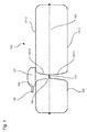
- Fig. 1 shows a schematic view of a liquid tank 100 for a motor vehicle.
- the liquid tank 100 is composed of a first liquid tank shell 111-1 and a second liquid tank shell 111-2, which are fluid-tightly welded together at the edge.
- the first liquid tank shell 111 - 1 has a first connection element 101 - 1 which extends from an inner wall 103 into the interior 105 of the liquid tank 100.
- the second liquid tank shell 111-2 has a second one Connecting element 101 - 2, which extends from an inner wall 103 of the liquid tank 100 into the interior 105 of the liquid tank 100.
- the liquid tank shells 111-1 and 111-2 are, for example, plastic moldings produced by injection molding.
- the plastics may include, for example, polyolefins such as polyethylene or polypropylene, polycarbonate, polystyrene, polyamide or polyoxymethylene (POM).
- the first and second connection elements 101-1 and 101-2 touch each other at a junction 107 and are connected to each other at this.
- the connection of the two connecting elements 101-1 and 101-2 can be realized by welding.
- the connecting elements 101-1 and 101-2 internally connect a bottom and top surfaces internally in the liquid tank 100 to each other and reduce deformation of the tank geometry at overpressure or underpressure, such as buckling or contraction.
- the connecting elements 101-1 and 101-2 are designed with a tubular geometry. In general, a plurality of connecting elements can also be arranged inside the liquid tank 100.
- the second connection element 101-2 comprises a passage opening 109 for the passage of a fluid.
- the fluid may be, for example, air, water or a fuel.
- the connecting elements 101-1 and 101-2 form a tie rod or connecting dome between both sides of the liquid tank 100. Since expansion of the liquid tank 100 is prevented by the connecting elements 101-1 and 101-2, it can be ensured that the passage opening 109 always is located at the intended position inside the liquid tank 100.
- a hood 127 is formed with a port 125, such as a ventilation port.
- the passage opening 109 is formed adjacent to the connection point 107 between the first and second connection elements 101-1 and 101-2. This allows the functions of the dip tube and a tie rod in a single multi-functional component summarize.
- a dip tube is formed, which serves to switch off a Be Davistlforung during refueling.
- the dip tube is thereby combined with the connecting elements 102-1 and 101-2.
- the projecting from above into the interior 105 of the liquid tank 100, tubular Connecting element 101-2 discharges the air displaced during filling from the liquid tank 100. If the rising liquid level overflows the passage opening 109, no further air can escape.
- the pressure in the remaining air bubble in the liquid tank 100 increases.
- the fluid in a filler pipe rises to the liquid tank 100 beyond the level of the liquid level in the liquid tank 100. This leads to a shutdown of the fuel nozzle without the liquid tank 100 is overcrowded. In this way, the liquid tank 100 is prevented from being filled beyond a predefined level
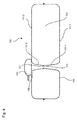
- Fig. 2 shows a schematic view of another embodiment of the liquid tank 100.
- the passage opening 109 adjacent to the inner wall 103 of the liquid tank 100 is formed.
- the passage opening 109 can be used for completely venting the liquid tank 100.
- a U-shaped channel 113 for a liquid closure is formed inside the connecting element 101-2. Gravity holds part of the liquid 129 in a lower part of the U-shaped channel 113, so that the liquid 129 forms a gas-tight seal.
- Fig. 3 shows a schematic view of another embodiment of the liquid tank 100.
- the connecting element 101-2 comprises a screen 115 for filtering the fluid. Through the screen 115 foreign bodies are retained, which are in fluid flow through the connecting element 101-2. In this way, another function can be integrated into the interior of the connecting element 101-2, resulting in even greater space savings.
- the second connection element 101-2 comprises a valve 117 for blocking a fluid direction.
- the valve 117 is, for example, a check valve or a check valve which allows the flow of the fluid in only one direction. In this way, the flow direction in the interior of the connecting element 101-2 can be controlled.
- Fig. 4 shows a schematic view of another embodiment of the liquid tank 100.
- the connection point 107 has a connection opening 119.
- the fluid, the through the passage opening 117 or exits, lead to the opposite side of the liquid tank 100.
- the passage opening 109 is formed in the region of the inner wall 103 of the liquid tank 100.
- the connecting element 101-2 may have a plurality of differently arranged passage openings.
- a passage opening may be arranged opposite another passage opening. In a blockage of a passage opening by a floating object in this case, the fluid can still flow through the other passage opening on the opposite side. As a result, for example, a fluid passage into the connecting element 102-1 can be ensured.
- a plurality of passage openings may be arranged in the longitudinal direction along the second connection element 101-2.
- the fluid can flow out of or into the liquid tank at any height.
- a non-shown float may be provided in the connector 101-2. The position of the float changes with the liquid level in the interior of the connecting element 101-2. This can be used, for example, for the float closing a vent opening arranged in the upper part of the connecting element 101-2 when a predetermined fill level in the liquid tank 100 is reached. Thereby, a float valve inside the liquid tank 100 can be realized.
- connecting elements 101-1 and 101-2 are also advantageous, since in this case tensile forces can be transmitted in a straight line between the walls of the liquid tank 100 without producing deformations in the connecting elements 101-1 and 101-2.
- Fig. 5 shows a schematic view of another embodiment of the liquid tank 100.
- the connecting element 101-2 is divided by a partition 121 into a left chamber 123-1 and a right chamber 123-2.
- the two chambers 123-1 and 123-2 are hermetically separated from each other by the partition wall 121.
- the left-hand chamber 123 - 1 comprises a first through-opening 109 - 1 for filling the liquid tank 100.
- the first through-opening 109 - 1 is arranged in the region of the lower inner wall 103 of the liquid tank 100. This will drain the fluid from Bottom filled in the liquid tank 100.
- the first passage opening 109-1 is usually below the liquid level, so that foaming and blistering during filling of the liquid tank 100 is prevented.
- the right-hand chamber 123-2 comprises a second through-opening 109-2 for venting the liquid tank 100.
- the second through-opening 109-2 is arranged in the region of the upper inner wall 103 of the liquid tank 100. As a result, the liquid tank 100 can be filled almost completely before a venting or float valve coupled to the second passage opening 109-2 prevents further outflow.
- the connecting elements 101-1 and 101-2 thus serve not only for the transmission of tensile forces, but at the same time both as a filler neck for refueling of the liquid tank 100 and as a dip tube of Be Pavllbellusterung to limit the maximum level.
- weight savings and space savings can be achieved.
- a compactification is particularly advantageous in cramped space in motor vehicles.
- a stable embodiment of the dip tube is achieved by bilateral mechanical connection between a bottom and a ceiling of the liquid tank. Since bending or warping of the wall of the liquid tank is prevented by the connecting members 101-1 and 101-2, the through hole 109 is always located at the intended position inside the liquid tank 100. Swelling or contraction of the liquid tank 100 is due to the direct support prevented at the passage opening 109 for the dip tube, so that the predetermined by the passage opening 109 Abschaltrise does not change in pressure fluctuations.
Landscapes
- Engineering & Computer Science (AREA)
- Life Sciences & Earth Sciences (AREA)
- Sustainable Development (AREA)
- Sustainable Energy (AREA)
- Chemical & Material Sciences (AREA)
- Combustion & Propulsion (AREA)
- Transportation (AREA)
- Mechanical Engineering (AREA)
- Cooling, Air Intake And Gas Exhaust, And Fuel Tank Arrangements In Propulsion Units (AREA)
Applications Claiming Priority (1)
| Application Number | Priority Date | Filing Date | Title |
|---|---|---|---|
| DE102013105522.2A DE102013105522A1 (de) | 2013-05-29 | 2013-05-29 | Flüssigkeitstank für ein Kraftfahrzeug |
Publications (1)
| Publication Number | Publication Date |
|---|---|
| EP2808193A1 true EP2808193A1 (fr) | 2014-12-03 |
Family
ID=50774658
Family Applications (1)
| Application Number | Title | Priority Date | Filing Date |
|---|---|---|---|
| EP14169386.1A Withdrawn EP2808193A1 (fr) | 2013-05-29 | 2014-05-22 | Réservoir de liquide pour un véhicule automobile |
Country Status (2)
| Country | Link |
|---|---|
| EP (1) | EP2808193A1 (fr) |
| DE (1) | DE102013105522A1 (fr) |
Cited By (1)
| Publication number | Priority date | Publication date | Assignee | Title |
|---|---|---|---|---|
| WO2025219548A1 (fr) | 2024-04-19 | 2025-10-23 | OPmobility C-Power Belgium Research | Réservoir à carburant en matière plastique pour véhicule automobile |
Citations (8)
| Publication number | Priority date | Publication date | Assignee | Title |
|---|---|---|---|---|
| US1072371A (en) * | 1912-03-07 | 1913-09-02 | Joe C Stone | Alarm device for gasolene-tanks. |
| US1448580A (en) * | 1922-03-15 | 1923-03-13 | Walter L Tresemer | Valve |
| EP0068473A1 (fr) * | 1981-07-01 | 1983-01-05 | Gerhard KG | Réservoir pour fluide sous pression |
| EP1596057A2 (fr) * | 2004-05-14 | 2005-11-16 | Mann+Hummel Gmbh | Module d'alimentation en carburant |
| DE102009036911A1 (de) * | 2009-08-11 | 2011-02-17 | Magna Steyr Fuel Systems Gmbh | Treibstoffbehälter für Kraftfahrzeuge mit Zuganker |
| US20120037638A1 (en) * | 2009-04-23 | 2012-02-16 | Inergy Automotive Systems Research (Societe Anonyme) | Plastic fuel tank with improved creep resistance and method for the manufacture thereof |
| WO2012066647A1 (fr) * | 2010-11-17 | 2012-05-24 | 愛三工業株式会社 | Réservoir de carburant et son procédé de fabrication |
| EP2465662A2 (fr) * | 2010-12-17 | 2012-06-20 | Yachiyo Industry Co., Ltd. | Procédé pour coupler l'un à l'autre des composants intégrés dans un récipient creux |
-
2013
- 2013-05-29 DE DE102013105522.2A patent/DE102013105522A1/de not_active Withdrawn
-
2014
- 2014-05-22 EP EP14169386.1A patent/EP2808193A1/fr not_active Withdrawn
Patent Citations (8)
| Publication number | Priority date | Publication date | Assignee | Title |
|---|---|---|---|---|
| US1072371A (en) * | 1912-03-07 | 1913-09-02 | Joe C Stone | Alarm device for gasolene-tanks. |
| US1448580A (en) * | 1922-03-15 | 1923-03-13 | Walter L Tresemer | Valve |
| EP0068473A1 (fr) * | 1981-07-01 | 1983-01-05 | Gerhard KG | Réservoir pour fluide sous pression |
| EP1596057A2 (fr) * | 2004-05-14 | 2005-11-16 | Mann+Hummel Gmbh | Module d'alimentation en carburant |
| US20120037638A1 (en) * | 2009-04-23 | 2012-02-16 | Inergy Automotive Systems Research (Societe Anonyme) | Plastic fuel tank with improved creep resistance and method for the manufacture thereof |
| DE102009036911A1 (de) * | 2009-08-11 | 2011-02-17 | Magna Steyr Fuel Systems Gmbh | Treibstoffbehälter für Kraftfahrzeuge mit Zuganker |
| WO2012066647A1 (fr) * | 2010-11-17 | 2012-05-24 | 愛三工業株式会社 | Réservoir de carburant et son procédé de fabrication |
| EP2465662A2 (fr) * | 2010-12-17 | 2012-06-20 | Yachiyo Industry Co., Ltd. | Procédé pour coupler l'un à l'autre des composants intégrés dans un récipient creux |
Cited By (2)
| Publication number | Priority date | Publication date | Assignee | Title |
|---|---|---|---|---|
| WO2025219548A1 (fr) | 2024-04-19 | 2025-10-23 | OPmobility C-Power Belgium Research | Réservoir à carburant en matière plastique pour véhicule automobile |
| BE1032552B1 (fr) * | 2024-04-19 | 2025-11-17 | Opmobility C Power Belgium Res | Réservoir à carburant en matière plastique pour véhicule automobile |
Also Published As
| Publication number | Publication date |
|---|---|
| DE102013105522A1 (de) | 2014-12-04 |
Similar Documents
| Publication | Publication Date | Title |
|---|---|---|
| DE102011079091A1 (de) | Sammler für ein Kühlfluid und Wärmetauscher | |
| EP2363628A2 (fr) | Elément de couplage pour la liaison de deux extrémités de tuyaux | |
| DE4121324C2 (de) | Kraftstoffbehälter für ein Kraftfahrzeug | |
| EP3055156B1 (fr) | Tubulure de remplissage pour un contenant de fluide de fonctionnement d'un véhicule à moteur | |
| EP3368366B1 (fr) | Réservoir de carburant doté d'un clapet d'entrée anti-retour | |
| DE112018006349T5 (de) | Mehrkammerflüssigkeitsreservoir für ein kraftfahrzeug | |
| DE102013013212A1 (de) | Universelles Abschaltventil | |
| DE102010030456A1 (de) | Entlüftungsventil | |
| EP3368365B1 (fr) | Réservoir monté en selle comprenant un dispositif antiballotement | |
| EP3452325B1 (fr) | Système de réservoir d'un véhicule automobile muni d'un élément de modification du volume | |
| EP2883733B1 (fr) | Installation de réservoir pour un véhicule | |
| EP2808193A1 (fr) | Réservoir de liquide pour un véhicule automobile | |
| EP2842785A1 (fr) | Réservoir de véhicule utilitaire | |
| DE4100388C2 (fr) | ||
| EP3433520B1 (fr) | Soupape de purge et/ou d'aération pour un réservoir de liquide de fonctionnement | |
| DE102006032792A1 (de) | Vertikal geteilter Ausgleichsbehälter für Kühlflüssigkeit | |
| DE2148063A1 (de) | Vorrichtung zur be- und entlueftung von kraftstoffbehaeltern fuer verbrennungskraftmaschinen | |
| DE10233350B4 (de) | Behälterkombination mit einer zwei Kanäle besitzenden Verbindung zwischen den Behältern | |
| EP3199715B1 (fr) | Trop-plein pour un bac, en particulier évier | |
| DE102008014579B4 (de) | Offenes Be- und Entlüftungssystem für Dieselkraftstoffbehälter, eine Abschottung für ein offenes Be- und Entlüftungssystem für Dieselkraftstoffbehälter sowie Verfahren zur Be- und Entlüftung eines Dieselkraftstoffbehälters | |
| EP1673252A1 (fr) | Reservoir a carburant | |
| DE102005053815A1 (de) | Entlüftungseinheit für das System zum Be- und Entlüften eines Kraftstoffbehälters | |
| DE102005048696B4 (de) | Behälter mit Filtereinsatz | |
| DE112015005298B4 (de) | Wärmetauscher | |
| DE202013010174U1 (de) | Fülltasse für Luftbefeuchter und Luftbefeuchter |
Legal Events
| Date | Code | Title | Description |
|---|---|---|---|
| PUAI | Public reference made under article 153(3) epc to a published international application that has entered the european phase |
Free format text: ORIGINAL CODE: 0009012 |
|
| 17P | Request for examination filed |
Effective date: 20140522 |
|
| AK | Designated contracting states |
Kind code of ref document: A1 Designated state(s): AL AT BE BG CH CY CZ DE DK EE ES FI FR GB GR HR HU IE IS IT LI LT LU LV MC MK MT NL NO PL PT RO RS SE SI SK SM TR |
|
| AX | Request for extension of the european patent |
Extension state: BA ME |
|
| STAA | Information on the status of an ep patent application or granted ep patent |
Free format text: STATUS: THE APPLICATION IS DEEMED TO BE WITHDRAWN |
|
| 18D | Application deemed to be withdrawn |
Effective date: 20150604 |