EP2808201A1 - Beleuchtungs- und/oder Signalisierungsvorrichtung sowie optische Einheit für ein Motorfahrzeug, das diese Vorrichtung umfasst - Google Patents
Beleuchtungs- und/oder Signalisierungsvorrichtung sowie optische Einheit für ein Motorfahrzeug, das diese Vorrichtung umfasst Download PDFInfo
- Publication number
- EP2808201A1 EP2808201A1 EP20140169787 EP14169787A EP2808201A1 EP 2808201 A1 EP2808201 A1 EP 2808201A1 EP 20140169787 EP20140169787 EP 20140169787 EP 14169787 A EP14169787 A EP 14169787A EP 2808201 A1 EP2808201 A1 EP 2808201A1
- Authority
- EP
- European Patent Office
- Prior art keywords
- sources
- optical
- luminous flux
- guides
- flux
- Prior art date
- Legal status (The legal status is an assumption and is not a legal conclusion. Google has not performed a legal analysis and makes no representation as to the accuracy of the status listed.)
- Pending
Links
Images


Classifications
-
- F—MECHANICAL ENGINEERING; LIGHTING; HEATING; WEAPONS; BLASTING
- F21—LIGHTING
- F21S—NON-PORTABLE LIGHTING DEVICES; SYSTEMS THEREOF; VEHICLE LIGHTING DEVICES SPECIALLY ADAPTED FOR VEHICLE EXTERIORS
- F21S43/00—Signalling devices specially adapted for vehicle exteriors, e.g. brake lamps, direction indicator lights or reversing lights
- F21S43/20—Signalling devices specially adapted for vehicle exteriors, e.g. brake lamps, direction indicator lights or reversing lights characterised by refractors, transparent cover plates, light guides or filters
- F21S43/235—Light guides
- F21S43/247—Light guides with a single light source being coupled into the light guide
-
- F—MECHANICAL ENGINEERING; LIGHTING; HEATING; WEAPONS; BLASTING
- F21—LIGHTING
- F21S—NON-PORTABLE LIGHTING DEVICES; SYSTEMS THEREOF; VEHICLE LIGHTING DEVICES SPECIALLY ADAPTED FOR VEHICLE EXTERIORS
- F21S43/00—Signalling devices specially adapted for vehicle exteriors, e.g. brake lamps, direction indicator lights or reversing lights
- F21S43/10—Signalling devices specially adapted for vehicle exteriors, e.g. brake lamps, direction indicator lights or reversing lights characterised by the light source
- F21S43/13—Signalling devices specially adapted for vehicle exteriors, e.g. brake lamps, direction indicator lights or reversing lights characterised by the light source characterised by the type of light source
- F21S43/14—Light emitting diodes [LED]
-
- F—MECHANICAL ENGINEERING; LIGHTING; HEATING; WEAPONS; BLASTING
- F21—LIGHTING
- F21S—NON-PORTABLE LIGHTING DEVICES; SYSTEMS THEREOF; VEHICLE LIGHTING DEVICES SPECIALLY ADAPTED FOR VEHICLE EXTERIORS
- F21S43/00—Signalling devices specially adapted for vehicle exteriors, e.g. brake lamps, direction indicator lights or reversing lights
- F21S43/20—Signalling devices specially adapted for vehicle exteriors, e.g. brake lamps, direction indicator lights or reversing lights characterised by refractors, transparent cover plates, light guides or filters
- F21S43/235—Light guides
- F21S43/236—Light guides characterised by the shape of the light guide
- F21S43/237—Light guides characterised by the shape of the light guide rod-shaped
-
- F—MECHANICAL ENGINEERING; LIGHTING; HEATING; WEAPONS; BLASTING
- F21—LIGHTING
- F21S—NON-PORTABLE LIGHTING DEVICES; SYSTEMS THEREOF; VEHICLE LIGHTING DEVICES SPECIALLY ADAPTED FOR VEHICLE EXTERIORS
- F21S43/00—Signalling devices specially adapted for vehicle exteriors, e.g. brake lamps, direction indicator lights or reversing lights
- F21S43/20—Signalling devices specially adapted for vehicle exteriors, e.g. brake lamps, direction indicator lights or reversing lights characterised by refractors, transparent cover plates, light guides or filters
- F21S43/235—Light guides
- F21S43/242—Light guides characterised by the emission area
- F21S43/243—Light guides characterised by the emission area emitting light from one or more of its extremities
Definitions
- the present invention relates to a lighting and / or signaling device, in particular for a motor vehicle, and an optical unit comprising said device. It is particularly intended for position lights and / or daytime running lights, flashing or brake lights.
- Recent technologies have been developed, with devices provided with a light source, usually a light-emitting diode, and a light guide through which a light beam from the source is propagated.
- the light propagates in the guide by total reflection to an exit face, which projects the light so as to be seen by the vehicles that follow or precede.
- Light guides are indeed commonly made of a material absorbing part of the light flux they transmit. The amount of light emitted therefore depends on the thickness of material passed through.
- the car manufacturer who wishes to juxtapose several light guides, within the same optical unit, must ensure that the light flux transmitted by each of these guides are homogeneous. Otherwise, this leads to a unsightly appearance for users, especially when these light guides transmit a luminous flux of different color and / or intensity.
- the object of the invention is to homogenize the light fluxes transmitted by several optical guides, within the same optical block, in particular when these optical guides have different lengths.
- the lighting and / or signaling device of the invention in particular for a motor vehicle, comprises at least two sources of light flux and at least two optical guides of luminous flux having a longitudinal extension different from each other. other, and located so that each of said sources emits its luminous flux in one of said optical guides, said optical guides being made of a material able to absorb a part of the luminous flux which it transmits, said device being configured to correct an intensity luminous flux at the output of said optical guides.
- the invention also provides an optical unit for a motor vehicle, comprising a device as described above.
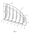
- the figure 1 shows a schematic view of an optical block 10, according to the invention, the curvature of which here has a curved portion 12 and another plane 14.
- Said optical block 10 comprises sources 1-6 of luminous flux F1-F6 and optical guides T1-T6 of said stream F1-F6.
- These optical guides T1-T6 have different lengths L1-L6. For reasons of readability, only the light flows F1 and F6 are represented; likewise, only the lengths L1 and L6 are indicated.
- the sources 1-6 of luminous flux F1-F6 are advantageously positioned on a common support 16 which is plane.
- This support 16 is, for example, a printed circuit board, in particular an insulated metal substrate, or any other means for supplying several light generators with electricity.
- the optical guides T1-T6 of luminous flux F1-F6 are each capable of transmitting a luminous flux F1-F6 by total reflection as it is propagated along its longitudinal axis.
- Said optical guides T1-T6 have an input face, in which each of said sources 1-6 emits its luminous flux F1-F6, and an output face which is remote from the input face of a length L1-L6 .
- Said optical guides T1-T6 are made of a material able to absorb a portion of the F1-F6 light flux they transmit. This material may be plastic - for example polymethyl methacrylate (PMMA) or polycarbonate (PC) - or any other material having reflective properties of a luminous flux.
- PMMA polymethyl methacrylate
- PC polycarbonate
- optical guides T1-T6 absorb about 1 to 5% of the F1-F6 light flux for about 10mm of material traversed.
- figure 1 represents an optical block 10 in which the optical guides T1-T6 have a length L1-L6 progressively increasing from L1 to L6 going from the optical guide T1 to the means T6. More precisely, the length of the path traveled by a light flux F1 in the optical guide T1 is D1 and the length of the path traveled by a light flux F6 in the optical guide T6 is equal to D6.
- the difference in length between L1 and L6, and a fortiori between D1 and D6, may be the order of 100mm in the case of a pronounced curve 12 such as that which is represented on the figure 1 .
- Said sources 1-6 each comprise one or more light generators associated or not with a reflector or any other optical element.
- the preferred light generator of the invention is a light emitting diode.
- the figure 2 presents a control means capable of supplying current to diodes 1'-6 'which are at the origin of the luminous flux F1-F6 emitted by the luminous flux sources 1-6.
- This control means is an integrated electrical circuit, as mentioned above, on a printed circuit board.
- the six diodes 1'-6 ' are grouped into two branches of three diodes. They are powered by a current generator 20.
- the device of the invention is configured to correct an intensity of the F1-F6 luminous flux at the output of said optical guides T1-T6.
- a first embodiment of the invention is to gradually reduce the current in each diode from the diode 6 'to the diode 1' (embodiment not shown).
- a second embodiment of the invention is to gradually increase the current in each diode from the diode 1 'to the diode 6' (embodiment not shown).
- a third embodiment of the invention is to increase the current in some diodes and reduce it in others (embodiment not shown).
- a fourth embodiment consists, as already stated, in choosing diodes 1'-6 'different from each other, so that the luminous flux emitted by the flux sources 1-6 comprising these diodes 1'-6', are different. This embodiment is illustrated in figure 2 .
- the figure 3 illustrates a fifth embodiment.
- each diode 1'-6 ' is disposed a resistance R1-R6 whose value varies. It is the weakest for the resistance R1 and increases progressively up to the resistance R6.
- the proportion of current derived in the resistor is higher for the resistor R1 than for the resistor R6.
- the diode 6 ' therefore emits more light flux than the diode 1'.
- the resistance R6 can even be infinite.
- the resistors R1-R6 can be adapted accordingly.
- FIG 4 presents a sixth embodiment of the invention.
- An absorbent material M1-M6 is injected into the optical guides T1-T6, said absorbent material being configured to absorb light so that the optical guides T1-T6 receiving said material M1-M6 transmit a reduced amount of light flux.
- Said absorbent material M1-M6 is injected over an increasing thickness Z1-Z6, from the longest optical guide T6 to the shortest optical guide T1. This leads to identical brightness flows at the output of the optical guides T1-T6.
- the figure 5 presents a seventh embodiment of the invention.
- An absorbent material M1-M6 is this time injected but it is more or less dense: the injected material M1-M6 has a greater and greater absorption of the flux source 6 towards the flux source 1.
- the differences absorption between the optical guides T1-T6, thus obtained, can also be achieved by the use of dyes or by injections of different M1-M6 materials.
- the absorbent zone M1-M6 may be located at other locations of the T1-T6 optical guides, rather than the end regions facing the light sources 1-6, as shown in FIGS. figures 4 and 5 . It is also conceivable that these absorbent zones M1-M6 cover the entirety of the optical guides T1-T6.
- the figure 6 presents an eighth embodiment of the invention.
- the sources are represented progressively defocused along a longitudinal axis of said optical guide, away from the source, a distance J1 to J6. They can also be along an axis perpendicular to said axial axis axially, gradually decentering.
- the optical guides T1-T6 of luminous flux are, for example, in the form of light guides, preferably made of plastic material. They may be in the form of a bead, in which case said inlet face and said outlet face will be at each of the opposite longitudinal ends of the bead. They may alternatively be in the form of a plate in which case said inlet face and said outlet face will be at two opposite edge portions of the plate.
Landscapes
- Engineering & Computer Science (AREA)
- General Engineering & Computer Science (AREA)
- Physics & Mathematics (AREA)
- Microelectronics & Electronic Packaging (AREA)
- Optics & Photonics (AREA)
- Lighting Device Outwards From Vehicle And Optical Signal (AREA)
- Non-Portable Lighting Devices Or Systems Thereof (AREA)
Applications Claiming Priority (1)
| Application Number | Priority Date | Filing Date | Title |
|---|---|---|---|
| FR1354780A FR3006420B1 (fr) | 2013-05-28 | 2013-05-28 | Dispositif d'eclairage et/ou de signalisation et bloc optique pour vehicule a moteur comprenant ledit dispositif |
Publications (1)
| Publication Number | Publication Date |
|---|---|
| EP2808201A1 true EP2808201A1 (de) | 2014-12-03 |
Family
ID=49054740
Family Applications (1)
| Application Number | Title | Priority Date | Filing Date |
|---|---|---|---|
| EP20140169787 Pending EP2808201A1 (de) | 2013-05-28 | 2014-05-26 | Beleuchtungs- und/oder Signalisierungsvorrichtung sowie optische Einheit für ein Motorfahrzeug, das diese Vorrichtung umfasst |
Country Status (3)
| Country | Link |
|---|---|
| EP (1) | EP2808201A1 (de) |
| CN (1) | CN104214628B (de) |
| FR (1) | FR3006420B1 (de) |
Cited By (1)
| Publication number | Priority date | Publication date | Assignee | Title |
|---|---|---|---|---|
| WO2018024264A1 (de) * | 2016-08-05 | 2018-02-08 | ŠKODA AUTO a.s. | Kraftfahrzeugscheinwerfer und verfahren zur betätigung des scheinwerfers |
Citations (7)
| Publication number | Priority date | Publication date | Assignee | Title |
|---|---|---|---|---|
| EP1359369A2 (de) * | 2002-05-02 | 2003-11-05 | VALEO Beleuchtung Deutschland GmbH | Beleuchtung- und/oder Signalisierungvorrichtung für Kraftfahrzeuge |
| DE102010016633A1 (de) * | 2009-11-09 | 2011-05-12 | Hyundai Motor Co. | Lichtleitereinheit für eine Fahrzeugleuchte |
| EP2450726A1 (de) * | 2010-11-04 | 2012-05-09 | Valeo Vision | Lichtwellenleiter für Kraftfahrzeug |
| EP2476947A2 (de) * | 2011-01-14 | 2012-07-18 | Valeo Vision | Vorrichtung zur Beleuchtung oder Signalisierung mittels Lichtwellenleiter für Kraftfahrzeug |
| EP2518392A2 (de) * | 2011-04-29 | 2012-10-31 | Valeo Iluminacion, S.A. | Signalisierungsvorrichtung mit Stop- und Positionsfunktion, die einen Lichtwellenleiter benutzt und einen 3D-Effekt erzeugt |
| DE102011050738A1 (de) * | 2011-05-31 | 2012-12-06 | Dr. Ing. H.C. F. Porsche Aktiengesellschaft | Beleuchtungseinrichtung eines Kraftfahrzeugs |
| DE102011110630A1 (de) * | 2011-08-18 | 2013-02-21 | Volkswagen Aktiengesellschaft | Verfahren zur Ansteuerung von Leuchtmitteln einer Beleuchtungseinrichtung für ein Kraftzeug und Beleuchtungseinrichtung |
Family Cites Families (1)
| Publication number | Priority date | Publication date | Assignee | Title |
|---|---|---|---|---|
| CN202835112U (zh) * | 2012-08-30 | 2013-03-27 | 上海汽车集团股份有限公司 | 汽车后位置灯及包括其的尾灯、汽车 |
-
2013
- 2013-05-28 FR FR1354780A patent/FR3006420B1/fr active Active
-
2014
- 2014-05-26 EP EP20140169787 patent/EP2808201A1/de active Pending
- 2014-05-28 CN CN201410231899.8A patent/CN104214628B/zh active Active
Patent Citations (7)
| Publication number | Priority date | Publication date | Assignee | Title |
|---|---|---|---|---|
| EP1359369A2 (de) * | 2002-05-02 | 2003-11-05 | VALEO Beleuchtung Deutschland GmbH | Beleuchtung- und/oder Signalisierungvorrichtung für Kraftfahrzeuge |
| DE102010016633A1 (de) * | 2009-11-09 | 2011-05-12 | Hyundai Motor Co. | Lichtleitereinheit für eine Fahrzeugleuchte |
| EP2450726A1 (de) * | 2010-11-04 | 2012-05-09 | Valeo Vision | Lichtwellenleiter für Kraftfahrzeug |
| EP2476947A2 (de) * | 2011-01-14 | 2012-07-18 | Valeo Vision | Vorrichtung zur Beleuchtung oder Signalisierung mittels Lichtwellenleiter für Kraftfahrzeug |
| EP2518392A2 (de) * | 2011-04-29 | 2012-10-31 | Valeo Iluminacion, S.A. | Signalisierungsvorrichtung mit Stop- und Positionsfunktion, die einen Lichtwellenleiter benutzt und einen 3D-Effekt erzeugt |
| DE102011050738A1 (de) * | 2011-05-31 | 2012-12-06 | Dr. Ing. H.C. F. Porsche Aktiengesellschaft | Beleuchtungseinrichtung eines Kraftfahrzeugs |
| DE102011110630A1 (de) * | 2011-08-18 | 2013-02-21 | Volkswagen Aktiengesellschaft | Verfahren zur Ansteuerung von Leuchtmitteln einer Beleuchtungseinrichtung für ein Kraftzeug und Beleuchtungseinrichtung |
Cited By (1)
| Publication number | Priority date | Publication date | Assignee | Title |
|---|---|---|---|---|
| WO2018024264A1 (de) * | 2016-08-05 | 2018-02-08 | ŠKODA AUTO a.s. | Kraftfahrzeugscheinwerfer und verfahren zur betätigung des scheinwerfers |
Also Published As
| Publication number | Publication date |
|---|---|
| FR3006420B1 (fr) | 2017-08-11 |
| CN104214628A (zh) | 2014-12-17 |
| FR3006420A1 (fr) | 2014-12-05 |
| CN104214628B (zh) | 2018-12-21 |
Similar Documents
| Publication | Publication Date | Title |
|---|---|---|
| EP1857732B1 (de) | Vorrichtung zur Beleuchtung und/oder Signalisierung für Kraftfahrzeuge | |
| EP2738448A2 (de) | Beleuchtung und/oder Signalisierungsvorrichtung, insbesondere für Fahrzeug | |
| FR2974616A1 (fr) | Dispositif de signalisation avec fonctions "stop" et "position" utilisant un guide de lumiere et generant un effect 3d | |
| EP3150907B1 (de) | Optische vorrichtung und system zur signalisierung und/oder beleuchtung für kraftfahrzeug | |
| WO2015086925A2 (fr) | Dispositif lumineux | |
| EP3071449A1 (de) | Beleuchtungs- und/oder signalisierungssystem mit lichtleitern für ein fahrzeug | |
| FR3007823A1 (fr) | Dispositif lumineux | |
| EP3246622A1 (de) | Raumbeleuchtungssystem für fahrzeuge | |
| EP2833053B1 (de) | Beleuchtungs- und/oder Signalisierungsvorrichtung, und Scheinwerfereinheit für ein Motorfahrzeug, das diese Vorrichtung umfasst | |
| EP3025094B1 (de) | Beleuchtungsvorrichtung | |
| EP2803903B1 (de) | Signalleuchte für ein Kraftfahrzeug | |
| EP2900520A1 (de) | Beleuchtungsvorrichtung, insbesondere für ein kraftfahrzeug | |
| FR2914731A1 (fr) | Dispositif lumineux de signalisation susceptible d'emettre independamment deux faisceaux de signalisation de meme intensite et de luminances differentes | |
| EP2808201A1 (de) | Beleuchtungs- und/oder Signalisierungsvorrichtung sowie optische Einheit für ein Motorfahrzeug, das diese Vorrichtung umfasst | |
| FR3006745A1 (fr) | Dispositif d'eclairage et/ou de signalisation bi-couleur, notamment pour vehicule automobile | |
| FR3009601A1 (fr) | Dispositif d'eclairage et/ou de signalisation bi-couleur, notamment pour vehicule automobile | |
| EP3467375A1 (de) | Leuchtvorrichtung geringer dicke, und homogene beleuchtung | |
| EP1850065B1 (de) | Vorrichtung zur Lichtverteilung in Lichtleitern | |
| FR3043445B1 (fr) | Dispositif d’eclairage pour vehicule automobile | |
| FR2912806A1 (fr) | Feu de vehicule automobile. | |
| EP2896878A1 (de) | Lichtleiter für Beleuchtungs- und/oder Signalvorrichtung | |
| WO2024165319A1 (fr) | Dispositif lumineux de signalisation de véhicule automobile comprenant un guide de lumière flexible et transparent | |
| FR3006643A1 (fr) | Dispositif lumineux, notamment de vehicule automobile | |
| FR3013102A1 (fr) | Dispositif lumineux, module d'eclairage et/ou de signalisation et vehicule automobile | |
| EP3867563A1 (de) | Lichtmodul mit zwei fotometrischen funktionen mit unterschiedlichen lichtsignaturen |
Legal Events
| Date | Code | Title | Description |
|---|---|---|---|
| PUAI | Public reference made under article 153(3) epc to a published international application that has entered the european phase |
Free format text: ORIGINAL CODE: 0009012 |
|
| 17P | Request for examination filed |
Effective date: 20140526 |
|
| AK | Designated contracting states |
Kind code of ref document: A1 Designated state(s): AL AT BE BG CH CY CZ DE DK EE ES FI FR GB GR HR HU IE IS IT LI LT LU LV MC MK MT NL NO PL PT RO RS SE SI SK SM TR |
|
| AX | Request for extension of the european patent |
Extension state: BA ME |
|
| R17P | Request for examination filed (corrected) |
Effective date: 20150325 |
|
| RBV | Designated contracting states (corrected) |
Designated state(s): AL AT BE BG CH CY CZ DE DK EE ES FI FR GB GR HR HU IE IS IT LI LT LU LV MC MK MT NL NO PL PT RO RS SE SI SK SM TR |
|
| STAA | Information on the status of an ep patent application or granted ep patent |
Free format text: STATUS: EXAMINATION IS IN PROGRESS |
|
| 17Q | First examination report despatched |
Effective date: 20180607 |
|
| P01 | Opt-out of the competence of the unified patent court (upc) registered |
Effective date: 20230528 |
|
| REG | Reference to a national code |
Ref country code: DE Ref legal event code: R079 Free format text: PREVIOUS MAIN CLASS: B60Q0001260000 Ipc: F21S0043140000 Ref country code: DE Ref legal event code: R079 Ref document number: 602014093040 Country of ref document: DE Free format text: PREVIOUS MAIN CLASS: B60Q0001260000 Ipc: F21S0043140000 |
|
| GRAP | Despatch of communication of intention to grant a patent |
Free format text: ORIGINAL CODE: EPIDOSNIGR1 |
|
| STAA | Information on the status of an ep patent application or granted ep patent |
Free format text: STATUS: GRANT OF PATENT IS INTENDED |
|
| RIC1 | Information provided on ipc code assigned before grant |
Ipc: F21S 43/14 20180101AFI20251113BHEP Ipc: F21S 43/237 20180101ALI20251113BHEP Ipc: F21S 43/243 20180101ALI20251113BHEP Ipc: F21S 43/247 20180101ALI20251113BHEP |
|
| INTG | Intention to grant announced |
Effective date: 20251202 |
|
| RIN1 | Information on inventor provided before grant (corrected) |
Inventor name: GODBILLON, VINCENT Inventor name: PUENTE, JEAN-CLAUDE |
|
| GRAS | Grant fee paid |
Free format text: ORIGINAL CODE: EPIDOSNIGR3 |
|
| GRAA | (expected) grant |
Free format text: ORIGINAL CODE: 0009210 |
|
| STAA | Information on the status of an ep patent application or granted ep patent |
Free format text: STATUS: THE PATENT HAS BEEN GRANTED |