EP2808233A1 - Système et procédé de fonctionnement pour la régulation du niveau d'une cabine de conducteur d'un véhicule utilitaire par rapport au châssis du véhicule - Google Patents
Système et procédé de fonctionnement pour la régulation du niveau d'une cabine de conducteur d'un véhicule utilitaire par rapport au châssis du véhicule Download PDFInfo
- Publication number
- EP2808233A1 EP2808233A1 EP14000187.6A EP14000187A EP2808233A1 EP 2808233 A1 EP2808233 A1 EP 2808233A1 EP 14000187 A EP14000187 A EP 14000187A EP 2808233 A1 EP2808233 A1 EP 2808233A1
- Authority
- EP
- European Patent Office
- Prior art keywords
- distance
- cab
- height position
- sprung
- vehicle
- Prior art date
- Legal status (The legal status is an assumption and is not a legal conclusion. Google has not performed a legal analysis and makes no representation as to the accuracy of the status listed.)
- Granted
Links
Images

Classifications
-
- B—PERFORMING OPERATIONS; TRANSPORTING
- B60—VEHICLES IN GENERAL
- B60G—VEHICLE SUSPENSION ARRANGEMENTS
- B60G17/00—Resilient suspensions having means for adjusting the spring or vibration-damper characteristics, for regulating the distance between a supporting surface and a sprung part of vehicle or for locking suspension during use to meet varying vehicular or surface conditions, e.g. due to speed or load
- B60G17/015—Resilient suspensions having means for adjusting the spring or vibration-damper characteristics, for regulating the distance between a supporting surface and a sprung part of vehicle or for locking suspension during use to meet varying vehicular or surface conditions, e.g. due to speed or load the regulating means comprising electric or electronic elements
- B60G17/0152—Resilient suspensions having means for adjusting the spring or vibration-damper characteristics, for regulating the distance between a supporting surface and a sprung part of vehicle or for locking suspension during use to meet varying vehicular or surface conditions, e.g. due to speed or load the regulating means comprising electric or electronic elements characterised by the action on a particular type of suspension unit
- B60G17/0155—Resilient suspensions having means for adjusting the spring or vibration-damper characteristics, for regulating the distance between a supporting surface and a sprung part of vehicle or for locking suspension during use to meet varying vehicular or surface conditions, e.g. due to speed or load the regulating means comprising electric or electronic elements characterised by the action on a particular type of suspension unit pneumatic unit
-
- B—PERFORMING OPERATIONS; TRANSPORTING
- B62—LAND VEHICLES FOR TRAVELLING OTHERWISE THAN ON RAILS
- B62D—MOTOR VEHICLES; TRAILERS
- B62D33/00—Superstructures for load-carrying vehicles
- B62D33/06—Drivers' cabs
-
- B—PERFORMING OPERATIONS; TRANSPORTING
- B62—LAND VEHICLES FOR TRAVELLING OTHERWISE THAN ON RAILS
- B62D—MOTOR VEHICLES; TRAILERS
- B62D33/00—Superstructures for load-carrying vehicles
- B62D33/06—Drivers' cabs
- B62D33/063—Drivers' cabs movable from one position into at least one other position, e.g. tiltable, pivotable about a vertical axis, displaceable from one side of the vehicle to the other
- B62D33/073—Drivers' cabs movable from one position into at least one other position, e.g. tiltable, pivotable about a vertical axis, displaceable from one side of the vehicle to the other characterised by special adaptations of vehicle control devices
-
- B—PERFORMING OPERATIONS; TRANSPORTING
- B60—VEHICLES IN GENERAL
- B60G—VEHICLE SUSPENSION ARRANGEMENTS
- B60G17/00—Resilient suspensions having means for adjusting the spring or vibration-damper characteristics, for regulating the distance between a supporting surface and a sprung part of vehicle or for locking suspension during use to meet varying vehicular or surface conditions, e.g. due to speed or load
- B60G17/015—Resilient suspensions having means for adjusting the spring or vibration-damper characteristics, for regulating the distance between a supporting surface and a sprung part of vehicle or for locking suspension during use to meet varying vehicular or surface conditions, e.g. due to speed or load the regulating means comprising electric or electronic elements
- B60G17/016—Resilient suspensions having means for adjusting the spring or vibration-damper characteristics, for regulating the distance between a supporting surface and a sprung part of vehicle or for locking suspension during use to meet varying vehicular or surface conditions, e.g. due to speed or load the regulating means comprising electric or electronic elements characterised by their responsiveness, when the vehicle is travelling, to specific motion, a specific condition, or driver input
- B60G17/0165—Resilient suspensions having means for adjusting the spring or vibration-damper characteristics, for regulating the distance between a supporting surface and a sprung part of vehicle or for locking suspension during use to meet varying vehicular or surface conditions, e.g. due to speed or load the regulating means comprising electric or electronic elements characterised by their responsiveness, when the vehicle is travelling, to specific motion, a specific condition, or driver input to an external condition, e.g. rough road surface, side wind
-
- B—PERFORMING OPERATIONS; TRANSPORTING
- B60—VEHICLES IN GENERAL
- B60G—VEHICLE SUSPENSION ARRANGEMENTS
- B60G17/00—Resilient suspensions having means for adjusting the spring or vibration-damper characteristics, for regulating the distance between a supporting surface and a sprung part of vehicle or for locking suspension during use to meet varying vehicular or surface conditions, e.g. due to speed or load
- B60G17/02—Spring characteristics, e.g. mechanical springs and mechanical adjusting means
- B60G17/04—Spring characteristics, e.g. mechanical springs and mechanical adjusting means fluid spring characteristics
- B60G17/052—Pneumatic spring characteristics
- B60G17/0523—Regulating distributors or valves for pneumatic springs
-
- B—PERFORMING OPERATIONS; TRANSPORTING
- B62—LAND VEHICLES FOR TRAVELLING OTHERWISE THAN ON RAILS
- B62D—MOTOR VEHICLES; TRAILERS
- B62D33/00—Superstructures for load-carrying vehicles
- B62D33/06—Drivers' cabs
- B62D33/0604—Cabs insulated against vibrations or noise, e.g. with elastic suspension
- B62D33/0608—Cabs insulated against vibrations or noise, e.g. with elastic suspension pneumatic or hydraulic suspension
-
- B—PERFORMING OPERATIONS; TRANSPORTING
- B60—VEHICLES IN GENERAL
- B60G—VEHICLE SUSPENSION ARRANGEMENTS
- B60G2202/00—Indexing codes relating to the type of spring, damper or actuator
- B60G2202/10—Type of spring
- B60G2202/15—Fluid spring
- B60G2202/152—Pneumatic spring
-
- B—PERFORMING OPERATIONS; TRANSPORTING
- B60—VEHICLES IN GENERAL
- B60G—VEHICLE SUSPENSION ARRANGEMENTS
- B60G2204/00—Indexing codes related to suspensions per se or to auxiliary parts
- B60G2204/10—Mounting of suspension elements
- B60G2204/16—Mounting of vehicle body on chassis
- B60G2204/162—Cabins, e.g. for trucks, tractors
-
- B—PERFORMING OPERATIONS; TRANSPORTING
- B60—VEHICLES IN GENERAL
- B60G—VEHICLE SUSPENSION ARRANGEMENTS
- B60G2300/00—Indexing codes relating to the type of vehicle
- B60G2300/02—Trucks; Load vehicles
-
- B—PERFORMING OPERATIONS; TRANSPORTING
- B60—VEHICLES IN GENERAL
- B60G—VEHICLE SUSPENSION ARRANGEMENTS
- B60G2300/00—Indexing codes relating to the type of vehicle
- B60G2300/14—Buses
-
- B—PERFORMING OPERATIONS; TRANSPORTING
- B60—VEHICLES IN GENERAL
- B60G—VEHICLE SUSPENSION ARRANGEMENTS
- B60G2400/00—Indexing codes relating to detected, measured or calculated conditions or factors
- B60G2400/10—Acceleration; Deceleration
- B60G2400/104—Acceleration; Deceleration lateral or transversal with regard to vehicle
-
- B—PERFORMING OPERATIONS; TRANSPORTING
- B60—VEHICLES IN GENERAL
- B60G—VEHICLE SUSPENSION ARRANGEMENTS
- B60G2400/00—Indexing codes relating to detected, measured or calculated conditions or factors
- B60G2400/10—Acceleration; Deceleration
- B60G2400/106—Acceleration; Deceleration longitudinal with regard to vehicle, e.g. braking
-
- B—PERFORMING OPERATIONS; TRANSPORTING
- B60—VEHICLES IN GENERAL
- B60G—VEHICLE SUSPENSION ARRANGEMENTS
- B60G2400/00—Indexing codes relating to detected, measured or calculated conditions or factors
- B60G2400/20—Speed
- B60G2400/204—Vehicle speed
-
- B—PERFORMING OPERATIONS; TRANSPORTING
- B60—VEHICLES IN GENERAL
- B60G—VEHICLE SUSPENSION ARRANGEMENTS
- B60G2400/00—Indexing codes relating to detected, measured or calculated conditions or factors
- B60G2400/25—Stroke; Height; Displacement
- B60G2400/252—Stroke; Height; Displacement vertical
-
- B—PERFORMING OPERATIONS; TRANSPORTING
- B60—VEHICLES IN GENERAL
- B60G—VEHICLE SUSPENSION ARRANGEMENTS
- B60G2400/00—Indexing codes relating to detected, measured or calculated conditions or factors
- B60G2400/40—Steering conditions
- B60G2400/41—Steering angle
- B60G2400/412—Steering angle of steering wheel or column
-
- B—PERFORMING OPERATIONS; TRANSPORTING
- B60—VEHICLES IN GENERAL
- B60G—VEHICLE SUSPENSION ARRANGEMENTS
- B60G2400/00—Indexing codes relating to detected, measured or calculated conditions or factors
- B60G2400/80—Exterior conditions
- B60G2400/82—Ground surface
- B60G2400/821—Uneven, rough road sensing affecting vehicle body vibration
-
- B—PERFORMING OPERATIONS; TRANSPORTING
- B60—VEHICLES IN GENERAL
- B60G—VEHICLE SUSPENSION ARRANGEMENTS
- B60G2401/00—Indexing codes relating to the type of sensors based on the principle of their operation
- B60G2401/16—GPS track data
-
- B—PERFORMING OPERATIONS; TRANSPORTING
- B60—VEHICLES IN GENERAL
- B60G—VEHICLE SUSPENSION ARRANGEMENTS
- B60G2500/00—Indexing codes relating to the regulated action or device
- B60G2500/20—Spring action or springs
- B60G2500/204—Pressure regulating valves for air-springs
-
- B—PERFORMING OPERATIONS; TRANSPORTING
- B60—VEHICLES IN GENERAL
- B60G—VEHICLE SUSPENSION ARRANGEMENTS
- B60G2600/00—Indexing codes relating to particular elements, systems or processes used on suspension systems or suspension control systems
- B60G2600/02—Retarders, delaying means, dead zones, threshold values, cut-off frequency, timer interruption
-
- B—PERFORMING OPERATIONS; TRANSPORTING
- B60—VEHICLES IN GENERAL
- B60G—VEHICLE SUSPENSION ARRANGEMENTS
- B60G2800/00—Indexing codes relating to the type of movement or to the condition of the vehicle and to the end result to be achieved by the control action
- B60G2800/16—Running
- B60G2800/162—Reducing road induced vibrations
-
- B—PERFORMING OPERATIONS; TRANSPORTING
- B60—VEHICLES IN GENERAL
- B60G—VEHICLE SUSPENSION ARRANGEMENTS
- B60G2800/00—Indexing codes relating to the type of movement or to the condition of the vehicle and to the end result to be achieved by the control action
- B60G2800/90—System Controller type
- B60G2800/91—Suspension Control
- B60G2800/914—Height Control System
Definitions
- the invention relates to a system for level control of a cab of a commercial vehicle relative to a vehicle chassis.
- the invention further relates to an operating method for level control of a cab of a commercial vehicle relative to the vehicle chassis.
- Spring or damping mechanisms are known from the prior art for resiliently supporting the cab of a commercial vehicle on the vehicle chassis.
- the driver of the commercial vehicle better against road-related shocks, for example, by bumps or potholes are protected.
- the longest possible travel is desirable.
- a long travel requires a large gap between the cab and chassis and a correspondingly greater height of the commercial vehicle. This deteriorates the c w value and thus the fuel consumption of the commercial vehicle.
- Such systems are therefore inadequately suited to allow both a high suspension comfort as well as an efficient fuel consumption and to adapt the spring or damping system to the occurring in real road a variety of traffic and driving situations.
- air struts are used, which level itself via an internal or external lever system and valves and set in this way a fixed, not influenced distance between the cab and vehicle chassis.
- this spring mechanism when the cab moves due to suggestions from the ground or other influences relative to the chassis, actuated by an attached to the strut or internal lever a valve, so that during movements of the shock absorber air permanently discharged into the environment or air into the Shock is pumped as soon as the target position is left.
- a disadvantage of this spring mechanism is caused by the permanent air inlet and outlet high air consumption.
- An object of the invention is to provide a cab suspension of a commercial vehicle, which has both a high damping comfort and allows efficient operation of the motor vehicle.
- the system for level control of a cab of a utility vehicle relative to a vehicle chassis includes a sprung mounting for resiliently supporting the cab on the vehicle chassis, and a distance sensor configured to detect relative movements and / or a distance between the cab and the vehicle chassis , Cab is understood to mean that part of the structure of the vehicle that provides space for drivers and escorts.
- the vehicle chassis is also referred to below as a chassis or chassis.
- the system comprises a control means adapted to variably drive the sprung bearing, wherein signals of the distance sensing means are used to control the sprung bearing. Furthermore, the sprung mounting is adjustable to a first height position, so that the distance between the cab and the vehicle chassis is controlled by the control means to a first desired distance.
- control means is adapted to detect from the received signals of the distance sensor means, whether a deviation of the distance between the cab and chassis from the desired distance or from the zero position, for example, by a road bump, springs back to the desired distance or the zero position or not. If the control means recognizes a permanent deviation or a deviation from the desired position which is not caused by the normal spring movement, the control means can intervene to restore the setpoint distance. Similarly, a deviation from the parallel orientation of the cab to the chassis, for example, by the weight of a driver, whereby the cab lowers slightly in one place, detected by the distance sensor means and corrected by driving the sprung storage accordingly.
- the sprung bearing is additionally or alternatively adjustable to at least a second height position, so that the distance between the cab and vehicle chassis is controlled by the control means to a second desired distance.
- the sprung storage is height adjustable in at least two predetermined height positions. A changed height position of the sprung mounting changes the (nominal) distance between the cab and chassis and thus the predetermined zero position by which the cab can spring relative to the chassis.
- the sprung bearing is set by the control means to the first or the at least one second height position as a function of at least one parameter relating to a route and / or a driving state of the commercial vehicle.
- a particular advantage of the invention is therefore that the cab suspension can be adapted to the current driving conditions to select depending on the driving situation that height position of the sprung storage, which allows the best possible compromise from required suspension comfort and low fuel consumption.
- An example of a parameter regarding the route may be the current road type, so that the height position of the sprung bearing can be changed depending on whether the vehicle is traveling on a highway, a country road or a dirt road, for example.
- This has the advantage that in types of roads where road irregularities, potholes, etc. are more likely, the sprung bearing can be adjusted to the greater height position, thereby increasing the travel and increasing the ride comfort.
- the sprung storage can be lowered to a lower altitude position, so that the distance between the cab and chassis is adjusted to a lower target height.
- the spring length can be shortened without sacrificing comfort to reduce the gap between the cab and chassis to improve the c w value of the vehicle.
- An example of a parameter relating to the running state of the commercial vehicle used for setting the height position of the sprung bearing is the current running speed.
- the control means is preferably set up at travel speeds set a greater height position with a longer travel under a predetermined threshold value and, when the threshold value is exceeded, initiate a lowering to the lower height position and regulate the sprung mounting to the correspondingly smaller desired distance.
- the driving speed of the commercial vehicle is then small, if stronger vibrations or suggestions from the ground are to be expected.
- a smaller distance between the cab and the chassis has a disproportionate effect on the fuel efficiency of the vehicle.
- Another example of a possible parameter on the basis of which it can be decided whether the sprung position is set to a first height position or at least a second height position is the driver's steering activity.
- Other possible variables from which it can be deduced whether the suspension requirement is currently increased or decreased due to the current driving conditions are the lateral acceleration, the longitudinal acceleration or a vertical acceleration of the commercial vehicle, which can be detected by means of corresponding sensors.
- the movement of the driver's cab for example by means of the distance sensor means, can also be measured directly. If the movement of the driver's cab exceeds a predetermined threshold value, this can be interpreted as a measure of an increased need for suspension, so that in this situation the sprung mounting is set to a long position with a long distance between the cab and the chassis.
- the invention is not limited to the use of the aforementioned parameters such as vehicle speed, road type or lateral acceleration.
- further parameters can be used, from which it can be deduced whether the suspension requirement is currently increased or decreased due to the current driving circumstances, in order to reduce the height position for improving the fuel efficiency with reduced suspension requirement.
- the detected values of the aforementioned parameters are integrated over a predetermined time interval and then determined, whether the integrated value exceeds a predetermined threshold, so as to derive a more reliable statement about the current suspension needs.
- the system for level control of the cab can be designed so that the sprung storage is adjustable only to two different height positions, so that between a "comfort position" with high suspension height and large desired distance between the vehicle body and chassis and an "aerodynamic" with less suspension and less Specified distance between cab and chassis can be changed. This allows a situational adapted change of the suspension behavior of the commercial vehicle at an efficient cost.
- the sprung mounting can be adjustable to a plurality of different height positions, wherein each of the height positions corresponds to a predetermined desired distance between the vehicle body and chassis, on the compliance controls the control means after the height position has been set. It is also possible to provide a system for level control in which a stepless adjustment of the height position of the sprung storage is possible. This has the advantage that the cab suspension can be adapted to the current driving conditions even more flexible, depending on the driving situation to select the height position of the sprung storage, which allows the best possible compromise from the necessary suspension comfort and low fuel consumption.
- the sprung mounting for this purpose comprises a plurality of pneumatic and / or hydraulic spring elements, a central valve block for the variable supply of the spring elements with a pressure-generating medium and a supply unit, which provides the pressure-generating medium to the valve block.
- the control means is designed as a central control unit. The central control unit is set up to determine whether the desired position is restored in the case of a spring element after a deviation from the desired position by normal "compression". If not, this is detected by the control unit after a predetermined time by evaluating the signal of the distance sensor means. The control means can then by controlling the central valve block, the pressure level Control this spring element such that this spring element springs back to the set nominal distance.
- the "sluggish" control can also be realized if instead of a central control unit as a control means and instead of a central valve block on the spring elements in each case a valve and a control element are provided.
- the individual controllers receive the at least one parameter relating to a travel route and / or a driving state of the commercial vehicle in order to possibly change the height position of the sprung mounting.
- the controllers continue to receive via the signals of a distance sensor to be corrected deviation from the current desired position of the respective spring element.
- the regulators control the level of the pressure medium of the spring element via the valve in order to regulate it to the desired height position or to the nominal distance.
- the distance sensor means comprises distance sensors, for example position transducers, which respectively measure the spring movement and alignment of the individual spring elements between the vehicle body and the chassis.
- the sprung mounting comprises pneumatic struts, for example, four struts are provided for spring-mounted mounting of the cab on the chassis.
- shock absorbers are provided for mounting the cab on the chassis
- position transducers can be provided on each or only on three of the shock absorbers.
- Three measuring points of three distance sensors define a plane and thus the orientation of the driver's cab relative to the chassis. This can be dispensed with a fourth distance sensor.
- control means may be arranged to regulate the distance between the cab and vehicle chassis after re-reaching a switching condition, for example, after falling below a threshold previously exceeded, to the previous altitude position back. Preferably, however, is only returned to the first or the previous height position, if after the previous switching a predetermined dead time has passed. This can be avoided that in fluctuations of a parameter to the switching condition, such as the fluctuation of the vehicle speed by a predetermined limit, a back and forth change in the height position of the sprung storage and the distance between the cab and chassis.
- the invention further encompasses an operating method for the level control of a driver's cab of a commercial vehicle relative to a vehicle chassis, comprising the steps of: detecting a relative movement and / or a distance between the driver's cab and the vehicle chassis; Adjustment of a sprung mounting, which supports the cab resiliently on the vehicle chassis, to a first height position and control of the distance between the cab and vehicle chassis to at least a first target distance, wherein the detected relative movement and / or the distance between the cab and the vehicle chassis for control on the first nominal distance is used.
- the method of operation includes adjusting the sprung bearing to at least a second height position and controlling the distance between the cab and vehicle chassis to at least a second desired distance, wherein the detected relative movement and / or the distance between the cab and the vehicle chassis used to control the second target distance becomes.
- the sprung bearing is set to the first or the at least one second height position as a function of at least one parameter relating to a route and / or a driving state of the commercial vehicle.
- Fig. 1 and Fig. 2 illustrate a spring-mounted mounting of a cab 2 (shown in simplified form as a flat plate) on a vehicle chassis 1 (shown in simplified form as two parallel profile carrier).
- the cab 2 is resiliently mounted on the chassis 1 in parallel alignment via four spring-operated air-operated spring elements 3.
- the spring elements 3 are height adjustable.
- the spring elements 3 in two predetermined height positions h1 and h2 are adjustable, wherein the height position h1 is greater than the height position h2, which by comparing the Fig. 1 with the Fig. 2 is apparent.
- a changed height position h1; h2 of the sprung mounting changes the (target) distance between the cab (2) and chassis (1) and thus the predetermined zero position by which the cab (2) relative to the chassis (1) can spring for vertical suggestions.
- the smaller height position h2 of the sprung bearing in Fig. 2 shortens the available travel. Although this reduces the ride comfort, but also reduces the gap or distance between the chassis (1) and the cab (2).
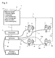
- Fig. 3 shows a schematic block diagram illustrating an embodiment of the present invention.
- spring elements 3 are in Fig. 3 shown as four struts 3, by means of which the cab (2, not shown) resiliently on the chassis (1, not shown) is mounted, each depending on a strut 3 at the front left (VL), the front right (VR), am rear left (HL) and at the rear right (HR) lower end of the cab (2) is located.
- the struts 3 are adjustable to two predetermined height positions h1, h2.
- a displacement transducer 4 is arranged, which measures the changes in length or the deviations of the springs 3 from the zero position.
- the measurement data determined by the displacement transducers 4 are transmitted by means of a signal line 11 to a central detection unit 7.
- the receiving unit 7 furthermore receives the measured values of one or more parameters 6 relating to the current route and / or a driving state of the vehicle via signal lines 11.
- parameters 6 relating to the current route and / or a driving state of the vehicle via signal lines 11.
- signals include the current driving speed of the vehicle, the current steering angle, GPS data by which the road type can be determined, acceleration data, which are detected for example by means of sensors for detecting the longitudinal and lateral acceleration or measurement data on the cabin movement.
- the parameter data 6 are transmitted to a central control unit 5, which evaluates the received parameter values 6.
- the central control unit 5 is further connected to a central valve block 8 via a signal line 11 for controlling the valve block 8.
- the valve block 8 is supplied via a pressure line 10 with compressed air from a compressed air supply unit 9.
- the valve block 8 is directly connected to at least three of the struts 3 via a compressed air line 10 to regulate the compressed air level in these struts 3 according to specification of the control unit 5.
- the rear right strut 3 is optionally supplied via a separate compressed air line 10 directly from the valve block 8 or alternatively can also be controlled only indirectly via the compressed air line 10a, which supplies both the rear left and the rear right strut 3 (illustrated by the dashed lines of compressed air 10a ).
- the latter allows less accurate compensation of deviations from the desired distance of the rear left and rear right strut, but is less expensive to implement and leads to sufficiently good results in practice.
- the control unit 5 combines two different control operations.
- a first control operation evaluates the parameter 6 transmitted to the control unit 5 regarding the route and / or the driving state of the vehicle.
- the control unit 5 additionally determines or stores the current height position h1; h2 of the spring elements 3.
- the parameter values 6 relating to the route and / or the driving state determine on the basis of predetermined assignments or threshold values whether the first (h1) or the second (h2) height position of the sprung bearing is set. If, for example, the driving speed exceeds a predetermined threshold value, then the struts 3 are moved from their first height position h1 into the second height position h2 (cf. Fig. 1 ) adjusted, if the struts 3 are currently set to the first height position h1.
- the central control unit 5 controls the valve block 8 via a signal line 11, so that the latter via the pressure lines 10, the height position h1; h2 of the struts 8 in the changed height position h1; h2. If the control unit 5 determines that the vehicle speed has fallen below the threshold again, the control unit 5 controls the central valve block 8 such that the struts 3 are returned to the first height position h1. In this case, it is checked in advance whether a predetermined dead time has passed after the last change in height of the struts 3 in order to avoid a constant back and forth when the vehicle speed varies by the predetermined threshold.
- control unit 5 monitors via the received output signals of the displacement transducer 4, whether the cab 2 is aligned parallel to the chassis 1 and whether the predetermined distance for the respective height position h1, h2 is maintained.
- the control unit 5 recognizes, by comparison of the measured values of the displacement transducers 4 of the individual struts 3, that a slight inclination of the driver's cab 2 with respect to the chassis 1 has arisen. Consequently, the control unit 5 controls the valve block 11 so that this corrected via the pressure line 10 which leads from the valve block 11 to the front left strut 3, the height of the front left strut 3 back to the desired distance of the currently set spring height.
- the control unit 5 is further set up to check at regular intervals, whether at all spring struts 3 for the current height position h1; h2 of the struts 2 predetermined target distance is maintained or whether "normal” spring movements are performed by the predetermined target distance. "Normal" spring movements to the specified distance occur during driving continuously on potholes, bumps or bad roads, etc. on.
- Fig. 3 illustrates a further variant of an embodiment in which, represented by the dashed lines, in addition a fourth displacement sensor 4a on the rear right strut 3 is arranged. Its measuring signals are in turn transmitted via a data line 11a via the receiving unit 7 to the control unit 5 and evaluated there.
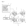
- Fig. 4 shows a further embodiment, which differs from the in Fig. 3
- the exemplary embodiment described differs essentially in that, instead of a central control unit 5, decentralized regulator valve combinations 13, 14 are arranged on the two front (VL, VR) spring struts 3 and one of the rear (HL) struts 3, whereby a central valve block 8 is dispensed with can.
- the regulator valve combinations 13, 14 are supplied via hose lines 10 with compressed air of a compressed air supply unit 9.
- the controllers 13 receive the previously described signals 6 concerning the route or the driving state of the commercial vehicle and in each case the signals of the position sensor 4, which performs the distance measurement on the strut 3 of the controller 13.
- the controller 13 control based on the received signals directly a valve 14 on the respective strut 3 to supply the transducer 4 with compressed air or compressed air from the Disengage transducer 4.
- the two different control operations can be realized separately for each strut 3 by each of the controllers 13: If the evaluation of the parameters 6 by the individual controllers 13 yields that another height position h1; h2 of the struts 3 is to be adjusted, by driving the valves 14, the new height position h1; h2 of the struts 3 is set. This is usually done by all controllers 13 at the same time to maintain the parallel orientation of the cab 2 relative to the chassis 1 in the change in distance. Furthermore, the controller 13 monitors the height position h1; h2 corresponding desired distance of the struts 3 and corrects the strut 3, if necessary, to the predetermined desired distance height.
- the rear right strut 3 is selectively (illustrated by the dashed lines of compressed air 10a) supplied via a separate compressed air line 10a directly from the compressed air supply 9 or alternatively can be controlled only indirectly via the compressed air line 10a, both the rear left (HL) and the rear right (HR) shock absorber 3 supplied.
- the controller 14 of the rear left (HL) suspension strut 3 also controls the compressed air level at the rear right (HR) strut 3, so that a separate regulator 14 on the rear right (HR) strut 3 can be dispensed with.
- Fig. 4 also illustrates a further variant of an embodiment in which, additionally illustrated by the dashed lines, a fourth displacement sensor 4a on the rear right (HR) shock absorber 3 is arranged. Whose measurement signals are in turn transmitted via a data line 11a to the controller 14 of this shock absorber 3 and evaluated there.
- a fourth displacement sensor 4a on the rear right (HR) shock absorber 3 is arranged. Whose measurement signals are in turn transmitted via a data line 11a to the controller 14 of this shock absorber 3 and evaluated there.
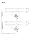
- Fig. 5 exemplifies an operating method according to an embodiment.
- the sprung bearing between the cab 2 and chassis 1 is set to a first height position.
- the cab 2 has a predetermined first target distance to the vehicle chassis 1.
- control checks the control means 5, 13 at regular intervals, whether the first target distance is maintained by all spring elements 3 taking into account the normal rebound and controls in case of deviations, the individual spring elements 3 back to the predetermined desired distance.
- Step S2 illustrates that the current measured values of the parameter 6 relating to the route or the driving state are continuously recorded.
- step S3 by evaluating the Parameter values 6 checked whether a predetermined threshold or a predetermined switching condition is reached. If NO, the parameter values 6 are still determined and monitored. If YES, this means that the current spring height of the spring elements 3 should be changed. Consequently, in step S4, the spring height is set to the second height position h2, so that a second desired distance between the cab 2 and chassis 1 is specified.
- step S5 as in step S2, the current measured values of the parameter 6 relating to the route or the driving state are continuously recorded, and in step S6 it is then decided on the basis of the measured values of the driving state and route parameters 6 whether the second height position h2 of the spring elements 3 is maintained is to be or whether to go back to the first height position h1. In this case, the control loop starts again at step S1.
Landscapes
- Engineering & Computer Science (AREA)
- Mechanical Engineering (AREA)
- Chemical & Material Sciences (AREA)
- Combustion & Propulsion (AREA)
- Transportation (AREA)
- Vehicle Body Suspensions (AREA)
- Body Structure For Vehicles (AREA)
Applications Claiming Priority (1)
| Application Number | Priority Date | Filing Date | Title |
|---|---|---|---|
| DE102013009204.3A DE102013009204A1 (de) | 2013-05-31 | 2013-05-31 | System und Betriebsverfahren zur Niveauregelung eines Fahrerhauses eines Nutzfahrzeugs gegenüber dem Fahrzeugchassis |
Publications (2)
| Publication Number | Publication Date |
|---|---|
| EP2808233A1 true EP2808233A1 (fr) | 2014-12-03 |
| EP2808233B1 EP2808233B1 (fr) | 2018-03-14 |
Family
ID=50002461
Family Applications (1)
| Application Number | Title | Priority Date | Filing Date |
|---|---|---|---|
| EP14000187.6A Active EP2808233B1 (fr) | 2013-05-31 | 2014-01-18 | Système et procédé de fonctionnement pour la régulation du niveau d'une cabine de conducteur d'un véhicule utilitaire par rapport au châssis du véhicule |
Country Status (7)
| Country | Link |
|---|---|
| US (1) | US9975582B2 (fr) |
| EP (1) | EP2808233B1 (fr) |
| CN (1) | CN104290825B (fr) |
| BR (1) | BR102014010461B1 (fr) |
| DE (1) | DE102013009204A1 (fr) |
| IN (1) | IN2014CH02604A (fr) |
| RU (1) | RU2655793C2 (fr) |
Cited By (1)
| Publication number | Priority date | Publication date | Assignee | Title |
|---|---|---|---|---|
| EP4008612A1 (fr) * | 2020-12-04 | 2022-06-08 | ContiTech Luftfedersysteme GmbH | Régulation de la position et de la hauteur d'une cabine de conducteur par rapport au châssis du véhicule |
Families Citing this family (21)
| Publication number | Priority date | Publication date | Assignee | Title |
|---|---|---|---|---|
| JP6482789B2 (ja) * | 2014-08-19 | 2019-03-13 | Kyb株式会社 | サスペンション制御装置 |
| US9511644B2 (en) * | 2014-09-18 | 2016-12-06 | Cnh Industrial America Llc | Liquid dispensing equipment with active suspension system |
| DE102015000718A1 (de) * | 2015-01-21 | 2016-07-21 | Man Truck & Bus Ag | Verfahren und Vorrichtung zur Niveauregelung eines gefederten Fahrzeugaufbaus |
| DE102015225136A1 (de) * | 2015-12-14 | 2017-06-14 | Robert Bosch Gmbh | Verfahren, elektronische Steuereinrichtung und System zur Positionsbestimmung |
| DE102016200403A1 (de) * | 2016-01-14 | 2017-07-20 | Zf Friedrichshafen Ag | Systemarchitektur für ein aktives Fahrwerksystem an einem Kraftfahrzeug |
| DE102017111105A1 (de) | 2017-05-22 | 2018-11-22 | Dr. Ing. H.C. F. Porsche Aktiengesellschaft | Verfahren und Fahrwerksystem zur Niveauregelung eines Fahrzeuges |
| CN107499409A (zh) * | 2017-09-01 | 2017-12-22 | 贵州晶源动力科技有限公司 | 平衡车架、汽车及车架平衡方法 |
| US20190163201A1 (en) * | 2017-11-30 | 2019-05-30 | Uber Technologies, Inc. | Autonomous Vehicle Sensor Compensation Using Displacement Sensor |
| US10668954B2 (en) * | 2017-11-30 | 2020-06-02 | John Payne | Cab and hood suspension with hood tilt |
| US10745065B2 (en) * | 2018-04-16 | 2020-08-18 | Howe & Howe Inc. | Vehicle with pneumatically suspended operator compartment |
| EP3733462B1 (fr) * | 2019-04-30 | 2024-01-24 | Volvo Car Corporation | Système de nettoyage de connecté à un système de suspension |
| RU203666U1 (ru) * | 2020-12-28 | 2021-04-15 | Публичное акционерное общество "КАМАЗ" | Механизм стабилизации и поворота кабины лесозаготовительной машины |
| RU207690U1 (ru) * | 2021-04-26 | 2021-11-11 | Публичное акционерное общество "КАМАЗ" | Механизм стабилизации кабины лесозаготовительной машины |
| CN113247117A (zh) * | 2021-05-25 | 2021-08-13 | 一汽解放青岛汽车有限公司 | 一种驾驶室高度调控系统及具有该系统的车辆 |
| CN113942587B (zh) * | 2021-11-24 | 2023-07-28 | 东风商用车有限公司 | 一种驾驶室悬置自动控制系统 |
| CN115195886B (zh) * | 2022-07-15 | 2023-05-30 | 东风商用车有限公司 | 一种驾驶室空气悬架系统、控制方法及车辆 |
| DE102022208208A1 (de) | 2022-08-08 | 2024-02-08 | Zf Friedrichshafen Ag | Fahrzeug mit einem Kabinenlagerungssystem mit passiven Drucklufterzeuger |
| DE102022208211A1 (de) | 2022-08-08 | 2024-02-08 | Zf Friedrichshafen Ag | Luftfeder mit integrierten Drucklufterzeuger sowie Kabinenlagerungssystem und Fahrzeug mit der Luftfeder |
| CN115447680B (zh) * | 2022-10-08 | 2023-06-16 | 东风柳州汽车有限公司 | 一种商用车驾驶室半主动悬置控制方法及系统 |
| CN116101005A (zh) * | 2023-01-10 | 2023-05-12 | 岚图汽车科技有限公司 | 一种弹簧高度调节方法、装置、电子设备以及存储介质 |
| SE547544C2 (en) * | 2023-11-21 | 2025-10-14 | Traton Ab | A method and a control arrangement for estimation of motion of a portion of a vehicle body, and methods and control arrangements for motion compensation, detection of a critical situation and detection of a miscalibration of sensors |
Citations (11)
| Publication number | Priority date | Publication date | Assignee | Title |
|---|---|---|---|---|
| EP0089794A2 (fr) * | 1982-03-19 | 1983-09-28 | LUCAS INDUSTRIES public limited company | Systèmes de suspension pour véhicule |
| US5083275A (en) * | 1988-04-08 | 1992-01-21 | Nissan Motor Company, Limited | Height control system for automotive suspension system with vehicle driving condition dependent variable target height |
| JPH06286649A (ja) * | 1993-03-30 | 1994-10-11 | Isuzu Motors Ltd | キヤブの姿勢制御装置 |
| JPH07156838A (ja) * | 1993-12-08 | 1995-06-20 | Isuzu Motors Ltd | キヤブの姿勢制御装置 |
| WO1998056642A1 (fr) * | 1997-06-13 | 1998-12-17 | Lord Corporation | Suspension controlable pour cabine de vehicule |
| WO1999024309A1 (fr) * | 1997-11-12 | 1999-05-20 | Case Corporation | Commande d'un systeme actif de suspension de vehicule de travail basee sur un parametre d'un autre systeme de vehicule |
| US20010044685A1 (en) * | 1999-07-15 | 2001-11-22 | William L. Schubert | Apparatus and method for facilitating reduction of vibration in a work vehicle having an active cab suspension system |
| US20040227050A1 (en) * | 2003-04-14 | 2004-11-18 | Erwin Haller | Device and method for springing a vehicle seat |
| EP1584545A2 (fr) * | 2004-04-06 | 2005-10-12 | MAN Nutzfahrzeuge Aktiengesellschaft | Suspension pour une cabine de véhicule utilitaire et procédé de commande de cette dernière |
| EP1724131A1 (fr) * | 2005-05-13 | 2006-11-22 | Grammer Ag | Dispositif et procédé pour la suspension d'une cabine de véhicule utilisant un ressort pneumatique avec chambre d'air additionnelle |
| JP2013100029A (ja) * | 2011-11-08 | 2013-05-23 | Isuzu Motors Ltd | キャブ姿勢制御装置 |
Family Cites Families (39)
| Publication number | Priority date | Publication date | Assignee | Title |
|---|---|---|---|---|
| DE3223140A1 (de) | 1982-06-22 | 1983-12-22 | Adam Opel AG, 6090 Rüsselsheim | Anordnung zur selbsttaetigen veraenderung des bodenabstandes der karosserie eines fahrzeuges |
| DE3328497A1 (de) | 1983-08-06 | 1985-02-14 | Volkswagenwerk Ag, 3180 Wolfsburg | Kraftfahrzeug mit mindestens einer niveaugeregelten achse |
| US5144558A (en) * | 1986-06-13 | 1992-09-01 | Nissan Motor Company, Limited | Actively controlled automotive suspension system with adjustable rolling-stability and/or pitching-stability |
| US4871189B1 (en) * | 1987-08-28 | 1998-03-17 | Charles A Van Breemen | Truck cab suspension system |
| JP2565384B2 (ja) * | 1988-09-30 | 1996-12-18 | 富士重工業株式会社 | 自動車用アクティブサスペンションの制御装置 |
| JPH02182521A (ja) * | 1989-01-10 | 1990-07-17 | Nissan Motor Co Ltd | サスペンション制御装置 |
| JP2541353B2 (ja) * | 1990-09-18 | 1996-10-09 | 三菱自動車工業株式会社 | 車両用アクティブサスペンション装置 |
| US5209316A (en) * | 1991-10-16 | 1993-05-11 | Applied Power Inc. | Truck cab suspension unit |
| DE19615737A1 (de) * | 1996-04-20 | 1997-10-16 | Daimler Benz Ag | Aktives Federungssystem |
| DE19648176B4 (de) * | 1996-11-21 | 2011-06-22 | WABCO GmbH, 30453 | Verfahren zur Steuerung der Schwingungsdämpfer in einem Fahrzeug mit einer Niveauregeleinrichtung |
| JP3385940B2 (ja) * | 1997-10-13 | 2003-03-10 | トヨタ自動車株式会社 | 車高調整装置 |
| US5899288A (en) * | 1997-11-12 | 1999-05-04 | Case Corporation | Active suspension system for a work vehicle |
| US6029764A (en) * | 1997-11-12 | 2000-02-29 | Case Corporation | Coordinated control of an active suspension system for a work vehicle |
| US6000703A (en) * | 1997-11-12 | 1999-12-14 | Case Corporation | Active suspension system for a work vehicle having adjustable performance parameters |
| JP3428414B2 (ja) * | 1998-01-12 | 2003-07-22 | トヨタ自動車株式会社 | 車両の車高調整装置 |
| DE19811809A1 (de) | 1998-03-18 | 1999-09-23 | Bayerische Motoren Werke Ag | Verfahren zur Verringerung des Auftriebes an der Hinterachse eines Kraftfahrzeuges |
| US6701235B2 (en) * | 2000-08-31 | 2004-03-02 | Tokico Ltd. | Suspension control system |
| US6830256B2 (en) * | 2002-03-16 | 2004-12-14 | Peter E. Bryant | Method and apparatus for rebound control |
| US20060267296A1 (en) * | 2002-04-23 | 2006-11-30 | Dodd C I | Electronic control of vehicle air suspension |
| AU2003262787A1 (en) * | 2002-08-21 | 2004-03-11 | Delphi Technologies, Inc. | Controlled truck cab suspension |
| AU2003262786A1 (en) * | 2002-08-21 | 2004-03-11 | Delphi Technologies, Inc. | Controlled truck cab suspension system |
| US6959932B2 (en) * | 2002-11-04 | 2005-11-01 | Volvo Trucks North America, Inc. | Electronic height control |
| EP1680290A4 (fr) * | 2003-10-17 | 2007-11-07 | Active Air Suspension Ltd | Commande de suspension de vehicule |
| KR100550070B1 (ko) * | 2003-11-26 | 2006-02-08 | 주식회사 만도 | 전자 제어 현가 장치와 이를 이용한 댐퍼 감쇠력 제어 방법 |
| EP1623856B1 (fr) * | 2004-08-06 | 2012-02-22 | Honda Motor Co., Ltd. | Système de réglage de suspension |
| US7715965B2 (en) * | 2004-10-15 | 2010-05-11 | Ford Global Technologies | System and method for qualitatively determining vehicle loading conditions |
| US20060091635A1 (en) * | 2004-10-29 | 2006-05-04 | Travis Cook | Closed pneumatic synchronization system for independent suspensions |
| DE102004057679A1 (de) * | 2004-11-29 | 2006-06-08 | Renault Agriculture | Fahrzeugkabinenlagerung |
| KR100777641B1 (ko) * | 2005-12-02 | 2007-11-21 | 주식회사 만도 | 신호 고착 판정 기능을 갖는 차고 조절용 현가 장치 및 그차고 제어 방법 |
| US7872764B2 (en) * | 2007-10-16 | 2011-01-18 | Magna Electronics Inc. | Machine vision for predictive suspension |
| DE102007056700B4 (de) * | 2007-11-24 | 2012-03-29 | Grammer Aktiengesellschaft | Vorrichtung mit einem Federungssystem sowie Verfahren zur Einstellung eines Federungssystems |
| DE602009001128D1 (de) * | 2008-03-26 | 2011-06-09 | Honda Motor Co Ltd | Vorrichtung zur Regelung einer Radaufhängung |
| FI124140B (fi) * | 2008-05-09 | 2014-03-31 | Sandvik Mining & Constr Oy | Ohjaamo ja menetelmä sen valmistamiseksi sekä kaivosajoneuvo |
| US8185269B2 (en) * | 2008-12-16 | 2012-05-22 | GM Global Technology Operations LLC | Active suspension system for a vehicle and method of operating the same |
| RU109085U1 (ru) * | 2011-03-30 | 2011-10-10 | Открытое акционерное общество "Красноярский завод лесного машиностроения" (ОАО "Краслешмаш") | Механизм выравнивания кабины лесопромышленной машины колесного типа |
| CN202186439U (zh) | 2011-08-08 | 2012-04-11 | 江阴圣世杰机械制造有限公司 | 驾驶室前悬置装置 |
| DE102011120428A1 (de) | 2011-12-07 | 2012-06-28 | Daimler Ag | Nutzfahrzeugvorrichtung mit einer Höhenverstelleinrichtung für ein Fahrerhaus |
| CN202368692U (zh) | 2011-12-22 | 2012-08-08 | 东风汽车公司 | 一种卡车驾驶室前悬置装置 |
| DE102011122386A1 (de) | 2011-12-24 | 2013-06-27 | Daimler Ag | Verfahren zur Verringerung des Luftwiderstands eines Omnibusses |
-
2013
- 2013-05-31 DE DE102013009204.3A patent/DE102013009204A1/de not_active Withdrawn
-
2014
- 2014-01-18 EP EP14000187.6A patent/EP2808233B1/fr active Active
- 2014-04-30 BR BR102014010461-5A patent/BR102014010461B1/pt active IP Right Grant
- 2014-05-15 US US14/278,455 patent/US9975582B2/en active Active
- 2014-05-26 RU RU2014121263A patent/RU2655793C2/ru active
- 2014-05-27 IN IN2604CH2014 patent/IN2014CH02604A/en unknown
- 2014-05-30 CN CN201410427381.1A patent/CN104290825B/zh active Active
Patent Citations (11)
| Publication number | Priority date | Publication date | Assignee | Title |
|---|---|---|---|---|
| EP0089794A2 (fr) * | 1982-03-19 | 1983-09-28 | LUCAS INDUSTRIES public limited company | Systèmes de suspension pour véhicule |
| US5083275A (en) * | 1988-04-08 | 1992-01-21 | Nissan Motor Company, Limited | Height control system for automotive suspension system with vehicle driving condition dependent variable target height |
| JPH06286649A (ja) * | 1993-03-30 | 1994-10-11 | Isuzu Motors Ltd | キヤブの姿勢制御装置 |
| JPH07156838A (ja) * | 1993-12-08 | 1995-06-20 | Isuzu Motors Ltd | キヤブの姿勢制御装置 |
| WO1998056642A1 (fr) * | 1997-06-13 | 1998-12-17 | Lord Corporation | Suspension controlable pour cabine de vehicule |
| WO1999024309A1 (fr) * | 1997-11-12 | 1999-05-20 | Case Corporation | Commande d'un systeme actif de suspension de vehicule de travail basee sur un parametre d'un autre systeme de vehicule |
| US20010044685A1 (en) * | 1999-07-15 | 2001-11-22 | William L. Schubert | Apparatus and method for facilitating reduction of vibration in a work vehicle having an active cab suspension system |
| US20040227050A1 (en) * | 2003-04-14 | 2004-11-18 | Erwin Haller | Device and method for springing a vehicle seat |
| EP1584545A2 (fr) * | 2004-04-06 | 2005-10-12 | MAN Nutzfahrzeuge Aktiengesellschaft | Suspension pour une cabine de véhicule utilitaire et procédé de commande de cette dernière |
| EP1724131A1 (fr) * | 2005-05-13 | 2006-11-22 | Grammer Ag | Dispositif et procédé pour la suspension d'une cabine de véhicule utilisant un ressort pneumatique avec chambre d'air additionnelle |
| JP2013100029A (ja) * | 2011-11-08 | 2013-05-23 | Isuzu Motors Ltd | キャブ姿勢制御装置 |
Cited By (1)
| Publication number | Priority date | Publication date | Assignee | Title |
|---|---|---|---|---|
| EP4008612A1 (fr) * | 2020-12-04 | 2022-06-08 | ContiTech Luftfedersysteme GmbH | Régulation de la position et de la hauteur d'une cabine de conducteur par rapport au châssis du véhicule |
Also Published As
| Publication number | Publication date |
|---|---|
| US9975582B2 (en) | 2018-05-22 |
| BR102014010461A2 (pt) | 2015-11-24 |
| DE102013009204A1 (de) | 2014-12-04 |
| RU2014121263A (ru) | 2015-12-10 |
| CN104290825A (zh) | 2015-01-21 |
| BR102014010461B1 (pt) | 2022-01-25 |
| RU2655793C2 (ru) | 2018-05-29 |
| EP2808233B1 (fr) | 2018-03-14 |
| IN2014CH02604A (fr) | 2015-07-03 |
| CN104290825B (zh) | 2019-06-18 |
| US20140358380A1 (en) | 2014-12-04 |
Similar Documents
| Publication | Publication Date | Title |
|---|---|---|
| EP2808233B1 (fr) | Système et procédé de fonctionnement pour la régulation du niveau d'une cabine de conducteur d'un véhicule utilitaire par rapport au châssis du véhicule | |
| DE112018001006B4 (de) | Fahrzeugverhaltenssteuereinrichtung | |
| EP3090890B1 (fr) | Procede de reglage ou de commande de la force d'amortissement d'amortisseurs reglables dans des vehicules automobiles, en particulier des vehicules utilitaires | |
| EP3504073B1 (fr) | Procédé de commande de l'amortisseur de vibrations d'une suspension | |
| DE102013102588B4 (de) | Fahrzeug-Höheneinstellvorrichtung für ein Motorrad | |
| DE69206936T2 (de) | Geräte und Methode zur Eichung eines Niveauregelungsmoduls | |
| DE4414022C2 (de) | Aktives Federungssystem | |
| DE102015205369A1 (de) | Verfahren zum Betrieb eines Federungssystems | |
| EP3274199B1 (fr) | Système de commande prédictive d'un châssis pour un véhicule utilitaire tout-terrain | |
| DE102009005381A1 (de) | Vorrichtung zum Federn einer Masse und Verfahren zum Einstellen und/oder Betreiben einer Fluidfeder | |
| EP2078624A2 (fr) | Appareil de surveillance de la pression pneumatique avec détection de l'accélération par le capteur de pression de pneumatique | |
| EP3466754B1 (fr) | Procédé et dispositif de réglage de la portée lumineuse d'un phare | |
| DE102018109578A1 (de) | Aufhängungssystem und verfahren zur steuerung | |
| WO2020126480A1 (fr) | Procédé d'adaptation d'une fonction de transmission d'un châssis actif d'un véhicule | |
| EP3156270A1 (fr) | Procede et dispositif d'adaptation de la force d'amortissement d'amortisseurs reglables dans des vehicules automobiles | |
| WO2009149863A1 (fr) | Dispositif de commande d'au moins un organe de réglage de cabine et/ou d'au moins un organe de réglage de siège et/ou d'au moins un organe de réglage de colonne de direction d'un véhicule utilitaire | |
| EP1451030B1 (fr) | Reglage de position d'un corps de voiture d'un vehicule | |
| DE102012010553B4 (de) | Verfahren zur Steuerung eines aktiven Fahrwerks | |
| DE69106793T2 (de) | Vorrichtung zur Aufhängungsregelung. | |
| DE102008052132B4 (de) | Verfahren und Vorrichtung zum Verbessern des Fahrverhaltens eines Kraftfahrzeugs | |
| DE102012024984A1 (de) | Verfahren zum Bestimmen einer Soll-Kurvenneigung eines Kraftfahrzeugs | |
| DE102018222763A1 (de) | Verfahren zur Bereitstellung eines Oberflächenprofils durch ein Erfassungsfahrzeug sowie Erfassungsfahrzeug, Empfängerfahrzeug und Analyseeinrichtung | |
| DE102017209751A1 (de) | Verfahren zur Bestimmung eines Reifendruckverlusts eines Fahrzeugs und Fahrzeug | |
| DE102005012673A1 (de) | Anordnung und Verfahren zur Niveausteuerung bzw. -regelung eines Fahrzeugaufbaus | |
| DE4337078C2 (de) | Aufhängungssteuerungssystem |
Legal Events
| Date | Code | Title | Description |
|---|---|---|---|
| PUAI | Public reference made under article 153(3) epc to a published international application that has entered the european phase |
Free format text: ORIGINAL CODE: 0009012 |
|
| 17P | Request for examination filed |
Effective date: 20141020 |
|
| AK | Designated contracting states |
Kind code of ref document: A1 Designated state(s): AL AT BE BG CH CY CZ DE DK EE ES FI FR GB GR HR HU IE IS IT LI LT LU LV MC MK MT NL NO PL PT RO RS SE SI SK SM TR |
|
| AX | Request for extension of the european patent |
Extension state: BA ME |
|
| RIC1 | Information provided on ipc code assigned before grant |
Ipc: B60G 17/052 20060101ALN20171012BHEP Ipc: B60G 17/0165 20060101ALN20171012BHEP Ipc: B60G 17/016 20060101ALN20171012BHEP Ipc: B62D 33/06 20060101AFI20171012BHEP |
|
| GRAP | Despatch of communication of intention to grant a patent |
Free format text: ORIGINAL CODE: EPIDOSNIGR1 |
|
| STAA | Information on the status of an ep patent application or granted ep patent |
Free format text: STATUS: GRANT OF PATENT IS INTENDED |
|
| RIC1 | Information provided on ipc code assigned before grant |
Ipc: B60G 17/052 20060101ALN20171013BHEP Ipc: B62D 33/06 20060101AFI20171013BHEP Ipc: B60G 17/016 20060101ALN20171013BHEP Ipc: B60G 17/0165 20060101ALN20171013BHEP |
|
| INTG | Intention to grant announced |
Effective date: 20171117 |
|
| GRAS | Grant fee paid |
Free format text: ORIGINAL CODE: EPIDOSNIGR3 |
|
| GRAA | (expected) grant |
Free format text: ORIGINAL CODE: 0009210 |
|
| STAA | Information on the status of an ep patent application or granted ep patent |
Free format text: STATUS: THE PATENT HAS BEEN GRANTED |
|
| AK | Designated contracting states |
Kind code of ref document: B1 Designated state(s): AL AT BE BG CH CY CZ DE DK EE ES FI FR GB GR HR HU IE IS IT LI LT LU LV MC MK MT NL NO PL PT RO RS SE SI SK SM TR |
|
| REG | Reference to a national code |
Ref country code: GB Ref legal event code: FG4D Free format text: NOT ENGLISH |
|
| REG | Reference to a national code |
Ref country code: CH Ref legal event code: EP Ref country code: AT Ref legal event code: REF Ref document number: 978600 Country of ref document: AT Kind code of ref document: T Effective date: 20180315 |
|
| REG | Reference to a national code |
Ref country code: IE Ref legal event code: FG4D Free format text: LANGUAGE OF EP DOCUMENT: GERMAN |
|
| REG | Reference to a national code |
Ref country code: DE Ref legal event code: R096 Ref document number: 502014007586 Country of ref document: DE |
|
| REG | Reference to a national code |
Ref country code: NL Ref legal event code: FP |
|
| REG | Reference to a national code |
Ref country code: SE Ref legal event code: TRGR |
|
| REG | Reference to a national code |
Ref country code: LT Ref legal event code: MG4D |
|
| PG25 | Lapsed in a contracting state [announced via postgrant information from national office to epo] |
Ref country code: FI Free format text: LAPSE BECAUSE OF FAILURE TO SUBMIT A TRANSLATION OF THE DESCRIPTION OR TO PAY THE FEE WITHIN THE PRESCRIBED TIME-LIMIT Effective date: 20180314 Ref country code: HR Free format text: LAPSE BECAUSE OF FAILURE TO SUBMIT A TRANSLATION OF THE DESCRIPTION OR TO PAY THE FEE WITHIN THE PRESCRIBED TIME-LIMIT Effective date: 20180314 Ref country code: CY Free format text: LAPSE BECAUSE OF FAILURE TO SUBMIT A TRANSLATION OF THE DESCRIPTION OR TO PAY THE FEE WITHIN THE PRESCRIBED TIME-LIMIT Effective date: 20180314 Ref country code: NO Free format text: LAPSE BECAUSE OF FAILURE TO SUBMIT A TRANSLATION OF THE DESCRIPTION OR TO PAY THE FEE WITHIN THE PRESCRIBED TIME-LIMIT Effective date: 20180614 Ref country code: LT Free format text: LAPSE BECAUSE OF FAILURE TO SUBMIT A TRANSLATION OF THE DESCRIPTION OR TO PAY THE FEE WITHIN THE PRESCRIBED TIME-LIMIT Effective date: 20180314 |
|
| PG25 | Lapsed in a contracting state [announced via postgrant information from national office to epo] |
Ref country code: GR Free format text: LAPSE BECAUSE OF FAILURE TO SUBMIT A TRANSLATION OF THE DESCRIPTION OR TO PAY THE FEE WITHIN THE PRESCRIBED TIME-LIMIT Effective date: 20180615 Ref country code: BG Free format text: LAPSE BECAUSE OF FAILURE TO SUBMIT A TRANSLATION OF THE DESCRIPTION OR TO PAY THE FEE WITHIN THE PRESCRIBED TIME-LIMIT Effective date: 20180614 Ref country code: RS Free format text: LAPSE BECAUSE OF FAILURE TO SUBMIT A TRANSLATION OF THE DESCRIPTION OR TO PAY THE FEE WITHIN THE PRESCRIBED TIME-LIMIT Effective date: 20180314 Ref country code: LV Free format text: LAPSE BECAUSE OF FAILURE TO SUBMIT A TRANSLATION OF THE DESCRIPTION OR TO PAY THE FEE WITHIN THE PRESCRIBED TIME-LIMIT Effective date: 20180314 |
|
| PG25 | Lapsed in a contracting state [announced via postgrant information from national office to epo] |
Ref country code: MT Free format text: LAPSE BECAUSE OF FAILURE TO SUBMIT A TRANSLATION OF THE DESCRIPTION OR TO PAY THE FEE WITHIN THE PRESCRIBED TIME-LIMIT Effective date: 20180314 |
|
| PG25 | Lapsed in a contracting state [announced via postgrant information from national office to epo] |
Ref country code: EE Free format text: LAPSE BECAUSE OF FAILURE TO SUBMIT A TRANSLATION OF THE DESCRIPTION OR TO PAY THE FEE WITHIN THE PRESCRIBED TIME-LIMIT Effective date: 20180314 Ref country code: PL Free format text: LAPSE BECAUSE OF FAILURE TO SUBMIT A TRANSLATION OF THE DESCRIPTION OR TO PAY THE FEE WITHIN THE PRESCRIBED TIME-LIMIT Effective date: 20180314 Ref country code: RO Free format text: LAPSE BECAUSE OF FAILURE TO SUBMIT A TRANSLATION OF THE DESCRIPTION OR TO PAY THE FEE WITHIN THE PRESCRIBED TIME-LIMIT Effective date: 20180314 Ref country code: AL Free format text: LAPSE BECAUSE OF FAILURE TO SUBMIT A TRANSLATION OF THE DESCRIPTION OR TO PAY THE FEE WITHIN THE PRESCRIBED TIME-LIMIT Effective date: 20180314 Ref country code: ES Free format text: LAPSE BECAUSE OF FAILURE TO SUBMIT A TRANSLATION OF THE DESCRIPTION OR TO PAY THE FEE WITHIN THE PRESCRIBED TIME-LIMIT Effective date: 20180314 |
|
| PG25 | Lapsed in a contracting state [announced via postgrant information from national office to epo] |
Ref country code: SK Free format text: LAPSE BECAUSE OF FAILURE TO SUBMIT A TRANSLATION OF THE DESCRIPTION OR TO PAY THE FEE WITHIN THE PRESCRIBED TIME-LIMIT Effective date: 20180314 Ref country code: SM Free format text: LAPSE BECAUSE OF FAILURE TO SUBMIT A TRANSLATION OF THE DESCRIPTION OR TO PAY THE FEE WITHIN THE PRESCRIBED TIME-LIMIT Effective date: 20180314 Ref country code: CZ Free format text: LAPSE BECAUSE OF FAILURE TO SUBMIT A TRANSLATION OF THE DESCRIPTION OR TO PAY THE FEE WITHIN THE PRESCRIBED TIME-LIMIT Effective date: 20180314 |
|
| REG | Reference to a national code |
Ref country code: DE Ref legal event code: R097 Ref document number: 502014007586 Country of ref document: DE |
|
| PG25 | Lapsed in a contracting state [announced via postgrant information from national office to epo] |
Ref country code: PT Free format text: LAPSE BECAUSE OF FAILURE TO SUBMIT A TRANSLATION OF THE DESCRIPTION OR TO PAY THE FEE WITHIN THE PRESCRIBED TIME-LIMIT Effective date: 20180716 |
|
| PLBE | No opposition filed within time limit |
Free format text: ORIGINAL CODE: 0009261 |
|
| STAA | Information on the status of an ep patent application or granted ep patent |
Free format text: STATUS: NO OPPOSITION FILED WITHIN TIME LIMIT |
|
| PG25 | Lapsed in a contracting state [announced via postgrant information from national office to epo] |
Ref country code: DK Free format text: LAPSE BECAUSE OF FAILURE TO SUBMIT A TRANSLATION OF THE DESCRIPTION OR TO PAY THE FEE WITHIN THE PRESCRIBED TIME-LIMIT Effective date: 20180314 |
|
| 26N | No opposition filed |
Effective date: 20181217 |
|
| PG25 | Lapsed in a contracting state [announced via postgrant information from national office to epo] |
Ref country code: SI Free format text: LAPSE BECAUSE OF FAILURE TO SUBMIT A TRANSLATION OF THE DESCRIPTION OR TO PAY THE FEE WITHIN THE PRESCRIBED TIME-LIMIT Effective date: 20180314 |
|
| PG25 | Lapsed in a contracting state [announced via postgrant information from national office to epo] |
Ref country code: MC Free format text: LAPSE BECAUSE OF FAILURE TO SUBMIT A TRANSLATION OF THE DESCRIPTION OR TO PAY THE FEE WITHIN THE PRESCRIBED TIME-LIMIT Effective date: 20180314 |
|
| REG | Reference to a national code |
Ref country code: CH Ref legal event code: PL |
|
| GBPC | Gb: european patent ceased through non-payment of renewal fee |
Effective date: 20190118 |
|
| REG | Reference to a national code |
Ref country code: DE Ref legal event code: R081 Ref document number: 502014007586 Country of ref document: DE Owner name: MAN TRUCK & BUS SE, DE Free format text: FORMER OWNER: MAN TRUCK & BUS AG, 80995 MUENCHEN, DE |
|
| PG25 | Lapsed in a contracting state [announced via postgrant information from national office to epo] |
Ref country code: LU Free format text: LAPSE BECAUSE OF NON-PAYMENT OF DUE FEES Effective date: 20190118 |
|
| REG | Reference to a national code |
Ref country code: BE Ref legal event code: MM Effective date: 20190131 |
|
| REG | Reference to a national code |
Ref country code: IE Ref legal event code: MM4A |
|
| PG25 | Lapsed in a contracting state [announced via postgrant information from national office to epo] |
Ref country code: BE Free format text: LAPSE BECAUSE OF NON-PAYMENT OF DUE FEES Effective date: 20190131 |
|
| PG25 | Lapsed in a contracting state [announced via postgrant information from national office to epo] |
Ref country code: LI Free format text: LAPSE BECAUSE OF NON-PAYMENT OF DUE FEES Effective date: 20190131 Ref country code: GB Free format text: LAPSE BECAUSE OF NON-PAYMENT OF DUE FEES Effective date: 20190118 Ref country code: CH Free format text: LAPSE BECAUSE OF NON-PAYMENT OF DUE FEES Effective date: 20190131 |
|
| PG25 | Lapsed in a contracting state [announced via postgrant information from national office to epo] |
Ref country code: IE Free format text: LAPSE BECAUSE OF NON-PAYMENT OF DUE FEES Effective date: 20190118 |
|
| REG | Reference to a national code |
Ref country code: AT Ref legal event code: MM01 Ref document number: 978600 Country of ref document: AT Kind code of ref document: T Effective date: 20190118 |
|
| PG25 | Lapsed in a contracting state [announced via postgrant information from national office to epo] |
Ref country code: TR Free format text: LAPSE BECAUSE OF FAILURE TO SUBMIT A TRANSLATION OF THE DESCRIPTION OR TO PAY THE FEE WITHIN THE PRESCRIBED TIME-LIMIT Effective date: 20180314 |
|
| PG25 | Lapsed in a contracting state [announced via postgrant information from national office to epo] |
Ref country code: AT Free format text: LAPSE BECAUSE OF NON-PAYMENT OF DUE FEES Effective date: 20190118 |
|
| PG25 | Lapsed in a contracting state [announced via postgrant information from national office to epo] |
Ref country code: IS Free format text: LAPSE BECAUSE OF FAILURE TO SUBMIT A TRANSLATION OF THE DESCRIPTION OR TO PAY THE FEE WITHIN THE PRESCRIBED TIME-LIMIT Effective date: 20180714 |
|
| PG25 | Lapsed in a contracting state [announced via postgrant information from national office to epo] |
Ref country code: HU Free format text: LAPSE BECAUSE OF FAILURE TO SUBMIT A TRANSLATION OF THE DESCRIPTION OR TO PAY THE FEE WITHIN THE PRESCRIBED TIME-LIMIT; INVALID AB INITIO Effective date: 20140118 |
|
| PG25 | Lapsed in a contracting state [announced via postgrant information from national office to epo] |
Ref country code: MK Free format text: LAPSE BECAUSE OF FAILURE TO SUBMIT A TRANSLATION OF THE DESCRIPTION OR TO PAY THE FEE WITHIN THE PRESCRIBED TIME-LIMIT Effective date: 20180314 |
|
| PGFP | Annual fee paid to national office [announced via postgrant information from national office to epo] |
Ref country code: NL Payment date: 20260122 Year of fee payment: 13 |
|
| PGFP | Annual fee paid to national office [announced via postgrant information from national office to epo] |
Ref country code: SE Payment date: 20260126 Year of fee payment: 13 |
|
| PGFP | Annual fee paid to national office [announced via postgrant information from national office to epo] |
Ref country code: DE Payment date: 20260127 Year of fee payment: 13 |
|
| PGFP | Annual fee paid to national office [announced via postgrant information from national office to epo] |
Ref country code: IT Payment date: 20260123 Year of fee payment: 13 |
|
| PGFP | Annual fee paid to national office [announced via postgrant information from national office to epo] |
Ref country code: FR Payment date: 20260127 Year of fee payment: 13 |