EP1724131A1 - Dispositif et procédé pour la suspension d'une cabine de véhicule utilisant un ressort pneumatique avec chambre d'air additionnelle - Google Patents
Dispositif et procédé pour la suspension d'une cabine de véhicule utilisant un ressort pneumatique avec chambre d'air additionnelle Download PDFInfo
- Publication number
- EP1724131A1 EP1724131A1 EP06113865A EP06113865A EP1724131A1 EP 1724131 A1 EP1724131 A1 EP 1724131A1 EP 06113865 A EP06113865 A EP 06113865A EP 06113865 A EP06113865 A EP 06113865A EP 1724131 A1 EP1724131 A1 EP 1724131A1
- Authority
- EP
- European Patent Office
- Prior art keywords
- air spring
- spring
- switched
- force
- speed
- Prior art date
- Legal status (The legal status is an assumption and is not a legal conclusion. Google has not performed a legal analysis and makes no representation as to the accuracy of the status listed.)
- Granted
Links
- 238000000034 method Methods 0.000 title claims abstract description 10
- 239000000725 suspension Substances 0.000 claims abstract description 49
- 238000006073 displacement reaction Methods 0.000 claims description 30
- 230000001133 acceleration Effects 0.000 claims description 18
- 238000013016 damping Methods 0.000 claims description 17
- 230000000153 supplemental effect Effects 0.000 claims 2
- 238000010586 diagram Methods 0.000 description 13
- 230000007704 transition Effects 0.000 description 11
- 230000009467 reduction Effects 0.000 description 5
- 230000008859 change Effects 0.000 description 4
- 108010066114 cabin-2 Proteins 0.000 description 3
- 238000011084 recovery Methods 0.000 description 3
- 230000001419 dependent effect Effects 0.000 description 2
- 230000000977 initiatory effect Effects 0.000 description 2
- 230000007935 neutral effect Effects 0.000 description 2
- 238000004904 shortening Methods 0.000 description 2
- 230000009471 action Effects 0.000 description 1
- 230000006978 adaptation Effects 0.000 description 1
- 230000005540 biological transmission Effects 0.000 description 1
- 230000008878 coupling Effects 0.000 description 1
- 238000010168 coupling process Methods 0.000 description 1
- 238000005859 coupling reaction Methods 0.000 description 1
- 238000001514 detection method Methods 0.000 description 1
- 238000007599 discharging Methods 0.000 description 1
- 238000011156 evaluation Methods 0.000 description 1
- 238000005457 optimization Methods 0.000 description 1
- 230000008569 process Effects 0.000 description 1
- 238000010025 steaming Methods 0.000 description 1
Images


Classifications
-
- B—PERFORMING OPERATIONS; TRANSPORTING
- B60—VEHICLES IN GENERAL
- B60G—VEHICLE SUSPENSION ARRANGEMENTS
- B60G17/00—Resilient suspensions having means for adjusting the spring or vibration-damper characteristics, for regulating the distance between a supporting surface and a sprung part of vehicle or for locking suspension during use to meet varying vehicular or surface conditions, e.g. due to speed or load
- B60G17/015—Resilient suspensions having means for adjusting the spring or vibration-damper characteristics, for regulating the distance between a supporting surface and a sprung part of vehicle or for locking suspension during use to meet varying vehicular or surface conditions, e.g. due to speed or load the regulating means comprising electric or electronic elements
- B60G17/0152—Resilient suspensions having means for adjusting the spring or vibration-damper characteristics, for regulating the distance between a supporting surface and a sprung part of vehicle or for locking suspension during use to meet varying vehicular or surface conditions, e.g. due to speed or load the regulating means comprising electric or electronic elements characterised by the action on a particular type of suspension unit
- B60G17/0155—Resilient suspensions having means for adjusting the spring or vibration-damper characteristics, for regulating the distance between a supporting surface and a sprung part of vehicle or for locking suspension during use to meet varying vehicular or surface conditions, e.g. due to speed or load the regulating means comprising electric or electronic elements characterised by the action on a particular type of suspension unit pneumatic unit
-
- B—PERFORMING OPERATIONS; TRANSPORTING
- B60—VEHICLES IN GENERAL
- B60G—VEHICLE SUSPENSION ARRANGEMENTS
- B60G17/00—Resilient suspensions having means for adjusting the spring or vibration-damper characteristics, for regulating the distance between a supporting surface and a sprung part of vehicle or for locking suspension during use to meet varying vehicular or surface conditions, e.g. due to speed or load
- B60G17/02—Spring characteristics, e.g. mechanical springs and mechanical adjusting means
- B60G17/04—Spring characteristics, e.g. mechanical springs and mechanical adjusting means fluid spring characteristics
- B60G17/052—Pneumatic spring characteristics
-
- B—PERFORMING OPERATIONS; TRANSPORTING
- B62—LAND VEHICLES FOR TRAVELLING OTHERWISE THAN ON RAILS
- B62D—MOTOR VEHICLES; TRAILERS
- B62D33/00—Superstructures for load-carrying vehicles
- B62D33/06—Drivers' cabs
- B62D33/0604—Cabs insulated against vibrations or noise, e.g. with elastic suspension
- B62D33/0608—Cabs insulated against vibrations or noise, e.g. with elastic suspension pneumatic or hydraulic suspension
-
- B—PERFORMING OPERATIONS; TRANSPORTING
- B60—VEHICLES IN GENERAL
- B60G—VEHICLE SUSPENSION ARRANGEMENTS
- B60G2202/00—Indexing codes relating to the type of spring, damper or actuator
- B60G2202/10—Type of spring
- B60G2202/15—Fluid spring
- B60G2202/152—Pneumatic spring
-
- B—PERFORMING OPERATIONS; TRANSPORTING
- B60—VEHICLES IN GENERAL
- B60G—VEHICLE SUSPENSION ARRANGEMENTS
- B60G2204/00—Indexing codes related to suspensions per se or to auxiliary parts
- B60G2204/10—Mounting of suspension elements
- B60G2204/16—Mounting of vehicle body on chassis
- B60G2204/162—Cabins, e.g. for trucks, tractors
-
- B—PERFORMING OPERATIONS; TRANSPORTING
- B60—VEHICLES IN GENERAL
- B60G—VEHICLE SUSPENSION ARRANGEMENTS
- B60G2300/00—Indexing codes relating to the type of vehicle
- B60G2300/08—Agricultural vehicles
- B60G2300/082—Tractors
-
- B—PERFORMING OPERATIONS; TRANSPORTING
- B60—VEHICLES IN GENERAL
- B60G—VEHICLE SUSPENSION ARRANGEMENTS
- B60G2400/00—Indexing codes relating to detected, measured or calculated conditions or factors
- B60G2400/10—Acceleration; Deceleration
- B60G2400/102—Acceleration; Deceleration vertical
-
- B—PERFORMING OPERATIONS; TRANSPORTING
- B60—VEHICLES IN GENERAL
- B60G—VEHICLE SUSPENSION ARRANGEMENTS
- B60G2400/00—Indexing codes relating to detected, measured or calculated conditions or factors
- B60G2400/20—Speed
- B60G2400/206—Body oscillation speed; Body vibration frequency
-
- B—PERFORMING OPERATIONS; TRANSPORTING
- B60—VEHICLES IN GENERAL
- B60G—VEHICLE SUSPENSION ARRANGEMENTS
- B60G2400/00—Indexing codes relating to detected, measured or calculated conditions or factors
- B60G2400/25—Stroke; Height; Displacement
- B60G2400/252—Stroke; Height; Displacement vertical
-
- B—PERFORMING OPERATIONS; TRANSPORTING
- B60—VEHICLES IN GENERAL
- B60G—VEHICLE SUSPENSION ARRANGEMENTS
- B60G2400/00—Indexing codes relating to detected, measured or calculated conditions or factors
- B60G2400/50—Pressure
- B60G2400/51—Pressure in suspension unit
- B60G2400/512—Pressure in suspension unit in spring
- B60G2400/5122—Fluid spring
- B60G2400/51222—Pneumatic
-
- B—PERFORMING OPERATIONS; TRANSPORTING
- B60—VEHICLES IN GENERAL
- B60G—VEHICLE SUSPENSION ARRANGEMENTS
- B60G2500/00—Indexing codes relating to the regulated action or device
- B60G2500/20—Spring action or springs
- B60G2500/204—Pressure regulating valves for air-springs
- B60G2500/2041—Pressure regulating valves for air-springs for variable volume air springs, e.g. using accumulators as expansion chambers
-
- B—PERFORMING OPERATIONS; TRANSPORTING
- B60—VEHICLES IN GENERAL
- B60G—VEHICLE SUSPENSION ARRANGEMENTS
- B60G2500/00—Indexing codes relating to the regulated action or device
- B60G2500/20—Spring action or springs
- B60G2500/22—Spring constant
-
- B—PERFORMING OPERATIONS; TRANSPORTING
- B60—VEHICLES IN GENERAL
- B60G—VEHICLE SUSPENSION ARRANGEMENTS
- B60G2600/00—Indexing codes relating to particular elements, systems or processes used on suspension systems or suspension control systems
- B60G2600/02—Retarders, delaying means, dead zones, threshold values, cut-off frequency, timer interruption
-
- B—PERFORMING OPERATIONS; TRANSPORTING
- B60—VEHICLES IN GENERAL
- B60G—VEHICLE SUSPENSION ARRANGEMENTS
- B60G2800/00—Indexing codes relating to the type of movement or to the condition of the vehicle and to the end result to be achieved by the control action
- B60G2800/16—Running
- B60G2800/162—Reducing road induced vibrations
Definitions
- the invention relates to a device and a method for suspension of a vehicle cabin by means of additional volumes, in particular a commercial vehicle cabin for commercial vehicles with at least one between the commercial vehicle cabin and a base frame arranged air spring for suspension of Nutzlegikabine and a control device for controlling the supply and discharge of at least one additional volume or from the air spring, according to the preambles of claims 1 and 9.
- Suspension devices for vehicle cabins are known in particular for damping a level deflection of the vehicle cabin when driving over uneven road surfaces, such as potholes.
- EP 1 188 608 A1 an active damping system for sprung vehicle seats, in which between a seat part and a lower part connected to the vehicle in addition to a mechanical flexible connection means, a pneumatic discharge device and a hydraulic actuator are arranged. Both the pneumatic unloading device and the hydraulic actuator are controlled as a function of a seat error signal, which is generated for example by a jerky level adjustment of the seat part, by a control device.
- Such hydraulic actuators require a connection to the electrical system of the vehicle, in particular a commercial vehicle, such as a tractor. Such a connection results in the action of actively damping the vehicle seat from the function of the electrical system and in particular its parameters is dependent, so that a vote of the parameters of the damping system on the parameters of the electrical system and thus an adaptation of the system to the respective commercial vehicle is required.
- suspension devices are simple in that the hydraulic actuator receives air by means of a compressor when receiving a position error signal with respect to the vehicle seat, which is acted upon by the weight of a driver and thereby an increased volume of air for sufficient damping of the vehicle seat is created.
- Such suspension devices have along their level adjustment on no comfort range, which extends over a longer portion of the mecanicver jossweges and thus represents a uniform suspension within this mecanicver eins Kunststoffes with the same restoring forces.
- air springs which have a linearly extending force-displacement air spring characteristic whose pitch is different depending on the design of the air spring and an applied additional volume.
- additional volumes are used, which are connected as the actual air volume of the air spring with the incoming and outgoing air spring.
- the adjustment of a comfort range is aimed at air springs for vehicle cabins generally due to better transmission values and the resulting higher comfort.
- Such a comfort range of the air spring characteristic is set in the factory so far that it can be used universally for different lanes and surfaces with different degrees of unevenness. Since very different requirements are placed on the optimization of the suspension device or a suspension system of the tractor vehicle cabin, in particular for tractors which travel both on the paved roadway and on a dirt road or even on a field, an initially set universal comfort range can only be a compromise for effective suspension of the vehicle cab in different terrain.
- a suspension device for a vehicle cabin which provides enhanced ride comfort for a user using the vehicle cabin in a comfort zone represented by a force-way air spring characteristic with very little or no slope , and in Hubend Schemeen, which are outside the comfort range, allows. Furthermore, it is an object of the invention to provide a method for suspension of the vehicle cabin by means of such a suspension device.
- the core idea of the invention is to provide a suspension device for a vehicle cabin, in particular utility vehicle cabins of commercial vehicles with at least one air spring arranged between the utility vehicle cabin and a base frame for suspension of the utility vehicle cabin and a control device for controlling the supply and discharge of at least one additional volume to or from the pneumatic spring
- the additional volume which can be supplied or discharged so that in the stroke end regions of the air spring the course of a force-displacement air spring characteristic during a deployment or / and return spring movement of the air spring in a first and a second region has no or only slight slope.
- the additional volume in the Hubend Schemeen is switched on or compared to Maintain comfort range that the air spring according to the characteristic of the force-displacement diagram either during the deflection or during their recovery or during both movements experiences no change in force.
- the addable and releasable extra vibration damping volume in the first and second regions is respectively less than in a third region between the first and second regions, which is the comfort region, during the deployment spring movement. or completely switched off, so that this results in a pressure increase during the deflection of the air spring in Hubend Schemeen, which leads to a shortening of the spring travel.
- a connection of the additional volume takes place in parts or completely, so that this results in a horizontally extending section within the force-displacement air spring characteristic. This leads to a return of the air spring with an additional volume of a value from a range of, for example, from 0.1 to 10 and to a reduced ringing.
- the additional volume in the first and second ranges for the deploy movement is respectively greater than in the third range, or fully engaged and complete during the return spring movement switched off or supplied with a lower proportion than in the third area.
- no pressure increase takes place in the first and second areas during the deflection movement of the spring, which is why the air spring apart or collapses without counterforce.
- reversing the direction of movement ie during the return spring movement takes place at a deflection of the vehicle cabin up an energy buildup or a progression and a deflection of the vehicle cabin down a deprivation of energy or depression. In both cases, the reverberation is greatly reduced thereby. There is thus a strong damping.
- the third range within the force-displacement air-spring characteristic is the comfort range of the suspension device as a function of further speed or acceleration values which lie below the first, second and third speed or acceleration values and optionally in dependence on predeterminable amplitude values the spring movement formed differently wide.
- a mode assigned to these values is called up within the control device, which defines the limits of the comfort range.
- the suspension device has at least one pneumatic directional control valve for supplying or discharging the additional volume.
- the control device comprises a arranged in the armrest of a vehicle seat control switch.
- the third area ie the comfort area, can be displaced by the user and by means of the control device within the force-displacement air spring characteristic by means of an actuating device such that the car is set to the desired level with sufficient vibration-damping first and second areas.
- a recognition device for recognizing a user using the vehicle cabin in particular by means of its weight, can be arranged.
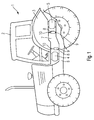
- Fig. 1 is shown in a schematic representation in side view of a tractor.
- the tractor 1 comprises a utility vehicle cabin 2 and the fender 3.
- each air spring 8 is connected at its lower end 9 to the base frame 6 and at its upper end 10 to the commercial vehicle cabin 2.
- the air springs can be stressed on train and on pressure.
- Both the damping bearings 4, 5 and the air springs 8 are adjustable in level so that they deflect downward under a pressure load due to driving through a pothole by the weights of the cab and driver and, for example after driving through a pothole, a deflection or a vibration upward Experienced.
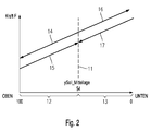
- Fig. 2 the mode "road” is reproduced in a force-displacement air spring characteristic diagram of the suspension device according to the invention.
- the abscissa represents a level adjustment path over 100 mm.
- the desired center position 11 of the vehicle cabin is drawn in terms of their height.
- the control device automatically switches to the "road" mode, in which both during the Ausstellfederzi and during the return spring movement an air spring characteristic is traversed with the usual slope without comfort range.
- a comfort area is unnecessary due to the stable sitting position in the middle position, which is possible because of the slight unevenness of a paved road.
- Fig. 3 the force-displacement air spring characteristic of the suspension device for the mode "transition road” is shown in a diagram.
- first region 18 and a second region 19 the air spring deflections and their provision by means of the arrows 23, 24 and 25, 26 reproduced.
- first region 18 which represents a degression region
- second region 19 which represents a progression region
- an increase in pressure during the deflection 25 leads to a return 26 into the comfort region 20.
- FIG. 4 shows in a diagram the force-displacement air spring characteristic of a suspension device in the mode "poor road / field etc.” shown. Again, the deployment and return spring movements 33, 34 and 35, 36 shown in a first and a second area 27, 28 run along the usual slope of the air spring characteristic.
- a wide comfort area with the characteristic sections 30, 31 is shown, which is formed due to the uneven ground, which is run over, relatively wide to provide maximum comfort.
- This mode is set at speeds of spring deflection of more than 0.114 and less than 0.228 m / s.
- the reference numeral 32 schematically illustrates the portion of the level adjustment path in which the vehicle cab can swing up and down within comfort range 29 with high comfort.
- the suspension device After the weight adjustment and the adjusted level, the suspension device automatically adjusts to the mode "transition road” at the start of the journey. Depending on the road condition and the resulting discharges into the suspension device or the spring deflections, the evaluation of speed or acceleration values of the spring deflection by means of the control device results in the mode “road” or “poor road / field etc.” selected. If no values for the mode "bad road / field etc.” are available, the priority mode "street” is selected.
- Fig. 5 the force-displacement air spring characteristic of the suspension device at medium speeds of the spring deflection is shown in a diagram.
- the width of a third area 39 which represents the comfort area, corresponds to the width of the comfort area shown in FIG. 4. This can also be recognized on the basis of a characteristic section 40.
- auxiliary volume is switched off at the beginning with an upwardly directed spring deflection according to the reference numeral 41, resulting in a pressure increase in the progression region shown here, which leads to a shortening of the spring travel.
- connection of the additional volume takes place, resulting in after the previous deceleration during Federausstellieri 41 results in an increase in force according to the reference numeral 42 to the level of the horizontally extending characteristic section 40.
- the air spring with the additional volume without slope of the curve is returned to the comfort area (see reference numeral 43).
- a second area 38 as well during a spring deflection down a deceleration is performed by initially switching off the additional volume (reference numeral 44). Subsequently, a connection of the additional volume at the transition to the return spring movement 45, 46 takes place, resulting in an initial power reduction to the level of the horizontally extending characteristic section 40 and then constructed according to reference numeral 46, a returning characteristic without inclination. Both times a reverberation is reduced.
- Fig. 6 the force-displacement air spring characteristic of the suspension device at a high speed of, for example, more than 0.3185 m / s and less than 0.353 m / s of the spring deflection is shown in a diagram.
- the additional volume is already switched on at the beginning of the spring deflection, ie when the limits of a comfort range 49 are exceeded, in a first and second region 47, 48 of the air spring characteristic. This results in a continuation to a characteristic section 50 horizontally without slope extending characteristic 51, 52 and 53, 54 during the deployment and return spring movement.
- Fig. 7 is shown in a diagram, the force-displacement air spring characteristic of the suspension device at a speed of more than 0.353 m / s of the spring deflection.
- the additional volume is initially switched on in the case of a transition from the third region or the comfort region 57.
Landscapes
- Engineering & Computer Science (AREA)
- Mechanical Engineering (AREA)
- Chemical & Material Sciences (AREA)
- Combustion & Propulsion (AREA)
- Transportation (AREA)
- Vehicle Body Suspensions (AREA)
- Seats For Vehicles (AREA)
Applications Claiming Priority (1)
| Application Number | Priority Date | Filing Date | Title |
|---|---|---|---|
| DE102005023090A DE102005023090B4 (de) | 2005-05-13 | 2005-05-13 | Vorrichtung und Verfahren zur Federung einer Fahrzeugkabine mittels Zusatzvolumina |
Publications (2)
| Publication Number | Publication Date |
|---|---|
| EP1724131A1 true EP1724131A1 (fr) | 2006-11-22 |
| EP1724131B1 EP1724131B1 (fr) | 2010-05-05 |
Family
ID=36603354
Family Applications (1)
| Application Number | Title | Priority Date | Filing Date |
|---|---|---|---|
| EP06113865A Not-in-force EP1724131B1 (fr) | 2005-05-13 | 2006-05-12 | Dispositif et procédé pour la suspension d'une cabine de véhicule utilisant un ressort pneumatique avec chambre d'air additionnelle |
Country Status (6)
| Country | Link |
|---|---|
| US (1) | US20060255623A1 (fr) |
| EP (1) | EP1724131B1 (fr) |
| CN (1) | CN100471748C (fr) |
| AT (1) | ATE466741T1 (fr) |
| DE (2) | DE102005023090B4 (fr) |
| ES (1) | ES2349950T3 (fr) |
Cited By (3)
| Publication number | Priority date | Publication date | Assignee | Title |
|---|---|---|---|---|
| EP2394843A3 (fr) * | 2010-06-08 | 2013-08-28 | Grammer Ag | Système de suspension pneumatique pour véhicules et procédé d'amortissement pneumatique de pièces de véhicules |
| EP2808233A1 (fr) * | 2013-05-31 | 2014-12-03 | MAN Truck & Bus AG | Système et procédé de fonctionnement pour la régulation du niveau d'une cabine de conducteur d'un véhicule utilitaire par rapport au châssis du véhicule |
| DE102015005966A1 (de) | 2015-05-08 | 2016-11-10 | Fludicon Gmbh | Verfahren und Vorrichtung zur Regelung oder Steuerung einer semiaktiven Dämpfereinrichtung eines Kraftfahrzeugs |
Families Citing this family (22)
| Publication number | Priority date | Publication date | Assignee | Title |
|---|---|---|---|---|
| DE102004021592A1 (de) * | 2004-05-03 | 2005-12-01 | Continental Aktiengesellschaft | Verfahren zur Luftmengenregelung in einer geschlossenen Luftversorgungsanlage für ein Fahrwerk |
| US8840172B2 (en) * | 2005-05-13 | 2014-09-23 | Grammer Ag | Device and method for suspension of a vehicle cabin by means of additional volumes |
| US8864145B2 (en) * | 2005-05-13 | 2014-10-21 | Grammer Ag | Device and method for suspension of a vehicle seat by means of additional volumes |
| DE102006059745A1 (de) | 2006-12-18 | 2008-06-19 | Grammer Ag | Luftfeder für einen Fahrzeugsitz sowie Fahrzeugsitz mit einer derartigen Luftfeder |
| DE102007032897B4 (de) | 2007-07-14 | 2014-05-28 | Grammer Aktiengesellschaft | Fahrzeugsitz mit einem Grundrahmen und einem gegenüber diesem Grundrahmen realtivbeweglichen Sitzrahmen |
| US7950726B2 (en) * | 2007-08-17 | 2011-05-31 | Brown Keith R | Air ride system for a tractor cab |
| DE102007056700B4 (de) | 2007-11-24 | 2012-03-29 | Grammer Aktiengesellschaft | Vorrichtung mit einem Federungssystem sowie Verfahren zur Einstellung eines Federungssystems |
| DE102008022045B3 (de) | 2008-05-03 | 2009-07-30 | Grammer Ag | Fahrzeugsitz mit einer Einrichtung zur Steuerung eines pneumatisch geregelten Federungssystems |
| DE102008052960B4 (de) | 2008-10-23 | 2014-02-13 | Grammer Aktiengesellschaft | Federungsschwingungssystem zur Schwingungsreduzierung |
| DE102008056200B4 (de) | 2008-11-06 | 2014-04-03 | Grammer Aktiengesellschaft | Scherengestell für einen Fahrzeugsitz, Fahrzeugsitz, insbesondere Kraftfahrzeugsitz, und Verfahren zum Herstellen eines Unterbaus eines Fahrzeugsitzes |
| DE102009005381B4 (de) | 2009-01-21 | 2013-05-08 | Grammer Aktiengesellschaft | Vorrichtung zum Federn einer Masse und Verfahren zum Einstellen und/oder Betreiben einer Fluidfeder |
| DE102010042673A1 (de) * | 2010-10-20 | 2012-04-26 | Deere & Company | Stabilisierungsvorrichtung für ein Kraftfahrzeug |
| DE102011004382A1 (de) * | 2011-02-18 | 2012-04-12 | Robert Bosch Gmbh | Fahrzeug mit einem Rahmen und einem relativ zu diesem schwingbeweglichen Fahrzeugaufbau |
| CN104228982B (zh) * | 2013-06-13 | 2017-04-19 | 南京农业大学 | 一种大型拖拉机新型全浮式驾驶室悬置结构 |
| CN105406191B (zh) * | 2015-12-09 | 2019-06-07 | 北京佰才邦技术有限公司 | 阵列天线馈电网络的调试方法和装置 |
| DE102016202755A1 (de) | 2016-02-23 | 2017-08-24 | Bayerische Motoren Werke Aktiengesellschaft | Fahrwerk und Verfahren zur Herstellung des Fahrwerks |
| CN107264609A (zh) * | 2017-06-28 | 2017-10-20 | 苏州见真物联科技有限公司 | 具有减震功能的婴儿车 |
| US10668954B2 (en) * | 2017-11-30 | 2020-06-02 | John Payne | Cab and hood suspension with hood tilt |
| US10745065B2 (en) * | 2018-04-16 | 2020-08-18 | Howe & Howe Inc. | Vehicle with pneumatically suspended operator compartment |
| CN113415117B (zh) * | 2021-05-14 | 2022-11-22 | 四川农业大学 | 一种小型底盘调平装置 |
| DE102021212935A1 (de) | 2021-11-17 | 2023-05-17 | Contitech Luftfedersysteme Gmbh | Vorrichtung zur Steuerung eines Innendrucks einer Luftfeder |
| JP7728226B2 (ja) * | 2022-04-20 | 2025-08-22 | 株式会社クボタ | 作業車 |
Citations (10)
| Publication number | Priority date | Publication date | Assignee | Title |
|---|---|---|---|---|
| US3966223A (en) * | 1974-11-08 | 1976-06-29 | Carr James P | Vehicle suspension |
| EP0089794A2 (fr) * | 1982-03-19 | 1983-09-28 | LUCAS INDUSTRIES public limited company | Systèmes de suspension pour véhicule |
| WO1989012766A1 (fr) * | 1988-06-22 | 1989-12-28 | The University Of Lancaster | Systeme de suspension |
| US5217210A (en) * | 1990-10-24 | 1993-06-08 | Mercedes-Benz Ag | Motor vehicle spring support system with computer-assisted control |
| US5255935A (en) * | 1990-03-09 | 1993-10-26 | Nippondenso Co., Ltd. | Air suspension system |
| US20010044685A1 (en) * | 1999-07-15 | 2001-11-22 | William L. Schubert | Apparatus and method for facilitating reduction of vibration in a work vehicle having an active cab suspension system |
| US20030015830A1 (en) * | 2001-07-20 | 2003-01-23 | Lord Corporation | Controlled equilibrium device with displacement dependent spring rates and integral damping |
| DE20214583U1 (de) * | 2002-09-20 | 2003-01-23 | Ivanovski, Lydia, 80797 München | Fahrzeug-Luftfeder |
| EP1464866A2 (fr) * | 2003-04-03 | 2004-10-06 | Vibracoustic GmbH & Co. KG | Ensemble ressort pneumatique |
| US20040227050A1 (en) * | 2003-04-14 | 2004-11-18 | Erwin Haller | Device and method for springing a vehicle seat |
Family Cites Families (25)
| Publication number | Priority date | Publication date | Assignee | Title |
|---|---|---|---|---|
| DE2717661C2 (de) * | 1977-04-21 | 1982-10-14 | Daimler-Benz Ag, 7000 Stuttgart | Vorbaueinheit für Lastkraftwagen |
| DE3025269A1 (de) * | 1980-07-03 | 1982-05-27 | Mannesmann Rexroth GmbH, 8770 Lohr | Stuetzeinheit fuer eine kabine an nutzfahrzeugen |
| US4451079A (en) * | 1981-06-03 | 1984-05-29 | Kabushiki Kaisha Komatsu Seisakusho | Operator's cab in a construction vehicle |
| US4463839A (en) * | 1981-11-06 | 1984-08-07 | Tokico Ltd. | Hydraulic damper |
| US4634142A (en) * | 1983-08-15 | 1987-01-06 | C & K Venture Income I-Coast | Computer optimized adaptive suspension system |
| JPS60103734U (ja) * | 1983-12-21 | 1985-07-15 | 自動車電機工業株式会社 | 油圧緩衝器 |
| JPS60183211A (ja) * | 1984-02-29 | 1985-09-18 | Nissan Motor Co Ltd | 車両用サスペンシヨン装置 |
| JPS60248416A (ja) * | 1984-05-21 | 1985-12-09 | Toyota Central Res & Dev Lab Inc | アクテイブサスペンシヨン装置 |
| US4726604A (en) * | 1985-01-28 | 1988-02-23 | Toyota Jidosha Kabushiki Kaisha | Rear suspension controller |
| JP2589067B2 (ja) * | 1985-10-01 | 1997-03-12 | トヨタ自動車株式会社 | サスペンシヨン制御装置 |
| JPH0450015A (ja) * | 1990-06-19 | 1992-02-19 | Mitsubishi Motors Corp | 車両用アクティブサスペンション装置 |
| JP2765341B2 (ja) * | 1992-02-14 | 1998-06-11 | 三菱自動車工業株式会社 | 車両用サスペンション装置 |
| JPH05238233A (ja) * | 1992-03-02 | 1993-09-17 | Toyota Motor Corp | サスペンションの制御装置 |
| EP0566091B1 (fr) * | 1992-04-17 | 1997-07-23 | Toyota Jidosha Kabushiki Kaisha | Système de réglage de suspension avec coefficient d'amortissement variable dépendant de la fréquence de force d'excitation |
| US5425436A (en) * | 1992-08-26 | 1995-06-20 | Nippondenso Co., Ltd. | Automotive suspension control system utilizing variable damping force shock absorber |
| JPH07156837A (ja) * | 1993-12-09 | 1995-06-20 | Isuzu Motors Ltd | キヤブの油圧式懸架装置 |
| JPH07215239A (ja) * | 1994-01-27 | 1995-08-15 | Isuzu Motors Ltd | キヤブの姿勢制御装置 |
| US5603387A (en) * | 1995-09-06 | 1997-02-18 | Applied Power, Inc. | Active vehicle suspension system |
| JPH1191623A (ja) * | 1997-09-18 | 1999-04-06 | Unisia Jecs Corp | キャブサスペンション制御装置 |
| US5941920A (en) * | 1997-11-12 | 1999-08-24 | Case Corporation | Control of an active suspension system for a work vehicle based upon a parameter of another vehicle system |
| US6029764A (en) * | 1997-11-12 | 2000-02-29 | Case Corporation | Coordinated control of an active suspension system for a work vehicle |
| US6000703A (en) * | 1997-11-12 | 1999-12-14 | Case Corporation | Active suspension system for a work vehicle having adjustable performance parameters |
| JP3787038B2 (ja) * | 1998-09-10 | 2006-06-21 | トヨタ自動車株式会社 | 弾性支持装置、車両用弾性支持装置及び車両用サスペンション装置のための制御装置 |
| US6371459B1 (en) * | 2000-09-05 | 2002-04-16 | Deere & Company | Active suspension with offload adjustment |
| JP4348934B2 (ja) * | 2002-09-25 | 2009-10-21 | アイシン・エィ・ダブリュ株式会社 | 車両のサスペンション制御装置 |
-
2005
- 2005-05-13 DE DE102005023090A patent/DE102005023090B4/de not_active Expired - Fee Related
-
2006
- 2006-05-10 CN CNB2006100819244A patent/CN100471748C/zh not_active Expired - Fee Related
- 2006-05-10 US US11/382,688 patent/US20060255623A1/en not_active Abandoned
- 2006-05-12 AT AT06113865T patent/ATE466741T1/de active
- 2006-05-12 ES ES06113865T patent/ES2349950T3/es active Active
- 2006-05-12 DE DE502006006884T patent/DE502006006884D1/de active Active
- 2006-05-12 EP EP06113865A patent/EP1724131B1/fr not_active Not-in-force
Patent Citations (10)
| Publication number | Priority date | Publication date | Assignee | Title |
|---|---|---|---|---|
| US3966223A (en) * | 1974-11-08 | 1976-06-29 | Carr James P | Vehicle suspension |
| EP0089794A2 (fr) * | 1982-03-19 | 1983-09-28 | LUCAS INDUSTRIES public limited company | Systèmes de suspension pour véhicule |
| WO1989012766A1 (fr) * | 1988-06-22 | 1989-12-28 | The University Of Lancaster | Systeme de suspension |
| US5255935A (en) * | 1990-03-09 | 1993-10-26 | Nippondenso Co., Ltd. | Air suspension system |
| US5217210A (en) * | 1990-10-24 | 1993-06-08 | Mercedes-Benz Ag | Motor vehicle spring support system with computer-assisted control |
| US20010044685A1 (en) * | 1999-07-15 | 2001-11-22 | William L. Schubert | Apparatus and method for facilitating reduction of vibration in a work vehicle having an active cab suspension system |
| US20030015830A1 (en) * | 2001-07-20 | 2003-01-23 | Lord Corporation | Controlled equilibrium device with displacement dependent spring rates and integral damping |
| DE20214583U1 (de) * | 2002-09-20 | 2003-01-23 | Ivanovski, Lydia, 80797 München | Fahrzeug-Luftfeder |
| EP1464866A2 (fr) * | 2003-04-03 | 2004-10-06 | Vibracoustic GmbH & Co. KG | Ensemble ressort pneumatique |
| US20040227050A1 (en) * | 2003-04-14 | 2004-11-18 | Erwin Haller | Device and method for springing a vehicle seat |
Non-Patent Citations (1)
| Title |
|---|
| PERRUCHOT M: "LES SUSPENSIONS. ÖLES SUSPENSIONS PNEUMATIQUES, APPLICATIONS SUR VEHICULES INDUSTRIELS", 1 May 1991, REVUE TECHNIQUE DIESEL, ETAI, BOULOGNE BILLANCOURT, FR, PAGE(S) XIII-XIV,XVI, ISSN: 0037-2579, XP000209803 * |
Cited By (6)
| Publication number | Priority date | Publication date | Assignee | Title |
|---|---|---|---|---|
| EP2394843A3 (fr) * | 2010-06-08 | 2013-08-28 | Grammer Ag | Système de suspension pneumatique pour véhicules et procédé d'amortissement pneumatique de pièces de véhicules |
| US8757600B2 (en) | 2010-06-08 | 2014-06-24 | Grammer Ag | Pneumatic springing system for vehicles and method for pneumatic springing of vehicle parts |
| EP2808233A1 (fr) * | 2013-05-31 | 2014-12-03 | MAN Truck & Bus AG | Système et procédé de fonctionnement pour la régulation du niveau d'une cabine de conducteur d'un véhicule utilitaire par rapport au châssis du véhicule |
| US9975582B2 (en) | 2013-05-31 | 2018-05-22 | Man Truck & Bus Ag | System and operating method for level regulation of a driver's cab of a commercial vehicle relative to the chassis of the vehicle |
| DE102015005966A1 (de) | 2015-05-08 | 2016-11-10 | Fludicon Gmbh | Verfahren und Vorrichtung zur Regelung oder Steuerung einer semiaktiven Dämpfereinrichtung eines Kraftfahrzeugs |
| EP3093170A1 (fr) | 2015-05-08 | 2016-11-16 | MAN Truck & Bus AG | Procede et dispositif de reglage ou de commande d'un dispositif d'amortissement semi-actif d'un vehicule automobile |
Also Published As
| Publication number | Publication date |
|---|---|
| DE102005023090A1 (de) | 2006-11-16 |
| CN100471748C (zh) | 2009-03-25 |
| EP1724131B1 (fr) | 2010-05-05 |
| US20060255623A1 (en) | 2006-11-16 |
| DE502006006884D1 (de) | 2010-06-17 |
| ATE466741T1 (de) | 2010-05-15 |
| ES2349950T3 (es) | 2011-01-13 |
| DE102005023090B4 (de) | 2009-04-09 |
| CN1880144A (zh) | 2006-12-20 |
Similar Documents
| Publication | Publication Date | Title |
|---|---|---|
| EP1721779B1 (fr) | Dispositif et méthode pour l'amortissement d'un siège de véhicule au moyen du volume additionnel | |
| EP1724131B1 (fr) | Dispositif et procédé pour la suspension d'une cabine de véhicule utilisant un ressort pneumatique avec chambre d'air additionnelle | |
| EP2048008B1 (fr) | Véhicule doté d'un siège de véhicule monté sur ressort et cabine de véhicule montée sur ressort ainsi que procédé de suspension à ressort | |
| EP2062758B1 (fr) | Dispositif doté d'un système de ressort et procédé de réglage d'un système de ressort | |
| DE10354635B4 (de) | Fahrzeugsitz mit automatischer Höheneinstellung und Verfahren hierfür | |
| DE102010026569B4 (de) | Regelungseinrichtung zur Reduzierung einer Schwingungsbewegung einer federkraftbeaufschlagten schwingenden Vorrichtung | |
| EP2818345B1 (fr) | Dispositif équipé d'un système de ressort | |
| DE19615737A1 (de) | Aktives Federungssystem | |
| EP3275705A1 (fr) | Procédé et dispositif de commande ou réglage de suspension de cabine de conducteur | |
| EP3323699B1 (fr) | Procédé et dispositif de commande ou réglage de suspension de cabine d'un véhicule automobile | |
| EP1468870B1 (fr) | Dispositif et procédé de suspension d'un siège de véhicule. | |
| WO2007115729A1 (fr) | Systeme de suspension pour un siege de vehicule | |
| EP2644417B1 (fr) | Procédé de réglage du niveau d'un véhicule automobile à suspension pneumatique | |
| DE69828763T2 (de) | Fahrzeughöhensteuerungsgerät | |
| EP3790748A1 (fr) | Système de commande de ressorts pneumatiques ainsi que véhicule muni dudit système et procédé afférent | |
| DE3818179C2 (fr) | ||
| EP3939828B1 (fr) | Siège de véhicule doté d'un amortissement adaptatif d'une unité oscillante affectée au siège de véhicule et procédé de réglage de l'amortissement de l'unité oscillante | |
| DE102019206506A1 (de) | Klassifizierung von Fahrbahnanomalitäten | |
| DE102009053277A1 (de) | Verfahren zum Ansteuern von einstellbaren Schwingungsdämpfern im Fahrwerk eines Kraftfahrzeugs | |
| DE102006051466A1 (de) | Flughafenschlepper mit Luftfederung | |
| DE102011000508A1 (de) | Verfahren zur Einstellung der Dämpfkraft für mindestens einen Schwingungsdämpfer | |
| DE102013008655B4 (de) | Verfahren zur Niveauregelung eines luftgefederten Kraftfahrzeugs | |
| DE102017112727A1 (de) | Virtueller Schwingungsdämpfer | |
| DE102020208902A1 (de) | Fahrzeugsitz umfassend eine Schwingeinheit, der ein Federsystem und ein Dämpfersystem zugeordnet ist, sowie Verfahren zur Einstellung einer Vorspannung eines Federsystems, welches mit dem Dämpfersystem zur adaptiven Dämpfung des Fahrzeugsitzes zusammenwirkt | |
| EP3733485A1 (fr) | Dispositif de montage d'une cabine de conducteur d'un véhicule automobile |
Legal Events
| Date | Code | Title | Description |
|---|---|---|---|
| PUAI | Public reference made under article 153(3) epc to a published international application that has entered the european phase |
Free format text: ORIGINAL CODE: 0009012 |
|
| AK | Designated contracting states |
Kind code of ref document: A1 Designated state(s): AT BE BG CH CY CZ DE DK EE ES FI FR GB GR HU IE IS IT LI LT LU LV MC NL PL PT RO SE SI SK TR |
|
| AX | Request for extension of the european patent |
Extension state: AL BA HR MK YU |
|
| 17P | Request for examination filed |
Effective date: 20070522 |
|
| AKX | Designation fees paid |
Designated state(s): AT BE BG CH CY CZ DE DK EE ES FI FR GB GR HU IE IS IT LI LT LU LV MC NL PL PT RO SE SI SK TR |
|
| 17Q | First examination report despatched |
Effective date: 20080104 |
|
| R17C | First examination report despatched (corrected) |
Effective date: 20080509 |
|
| R17C | First examination report despatched (corrected) |
Effective date: 20080515 |
|
| GRAP | Despatch of communication of intention to grant a patent |
Free format text: ORIGINAL CODE: EPIDOSNIGR1 |
|
| GRAS | Grant fee paid |
Free format text: ORIGINAL CODE: EPIDOSNIGR3 |
|
| GRAA | (expected) grant |
Free format text: ORIGINAL CODE: 0009210 |
|
| AK | Designated contracting states |
Kind code of ref document: B1 Designated state(s): AT BE BG CH CY CZ DE DK EE ES FI FR GB GR HU IE IS IT LI LT LU LV MC NL PL PT RO SE SI SK TR |
|
| REG | Reference to a national code |
Ref country code: GB Ref legal event code: FG4D Free format text: NOT ENGLISH |
|
| REG | Reference to a national code |
Ref country code: CH Ref legal event code: EP |
|
| REG | Reference to a national code |
Ref country code: IE Ref legal event code: FG4D Free format text: LANGUAGE OF EP DOCUMENT: GERMAN |
|
| REF | Corresponds to: |
Ref document number: 502006006884 Country of ref document: DE Date of ref document: 20100617 Kind code of ref document: P |
|
| REG | Reference to a national code |
Ref country code: SE Ref legal event code: TRGR |
|
| REG | Reference to a national code |
Ref country code: NL Ref legal event code: VDEP Effective date: 20100505 |
|
| LTIE | Lt: invalidation of european patent or patent extension |
Effective date: 20100505 |
|
| PG25 | Lapsed in a contracting state [announced via postgrant information from national office to epo] |
Ref country code: NL Free format text: LAPSE BECAUSE OF FAILURE TO SUBMIT A TRANSLATION OF THE DESCRIPTION OR TO PAY THE FEE WITHIN THE PRESCRIBED TIME-LIMIT Effective date: 20100505 Ref country code: LT Free format text: LAPSE BECAUSE OF FAILURE TO SUBMIT A TRANSLATION OF THE DESCRIPTION OR TO PAY THE FEE WITHIN THE PRESCRIBED TIME-LIMIT Effective date: 20100505 |
|
| BERE | Be: lapsed |
Owner name: GRAMMER A.G. Effective date: 20100531 |
|
| PG25 | Lapsed in a contracting state [announced via postgrant information from national office to epo] |
Ref country code: SI Free format text: LAPSE BECAUSE OF FAILURE TO SUBMIT A TRANSLATION OF THE DESCRIPTION OR TO PAY THE FEE WITHIN THE PRESCRIBED TIME-LIMIT Effective date: 20100505 Ref country code: FI Free format text: LAPSE BECAUSE OF FAILURE TO SUBMIT A TRANSLATION OF THE DESCRIPTION OR TO PAY THE FEE WITHIN THE PRESCRIBED TIME-LIMIT Effective date: 20100505 Ref country code: LV Free format text: LAPSE BECAUSE OF FAILURE TO SUBMIT A TRANSLATION OF THE DESCRIPTION OR TO PAY THE FEE WITHIN THE PRESCRIBED TIME-LIMIT Effective date: 20100505 Ref country code: IS Free format text: LAPSE BECAUSE OF FAILURE TO SUBMIT A TRANSLATION OF THE DESCRIPTION OR TO PAY THE FEE WITHIN THE PRESCRIBED TIME-LIMIT Effective date: 20100905 |
|
| REG | Reference to a national code |
Ref country code: IE Ref legal event code: FD4D |
|
| PG25 | Lapsed in a contracting state [announced via postgrant information from national office to epo] |
Ref country code: MC Free format text: LAPSE BECAUSE OF NON-PAYMENT OF DUE FEES Effective date: 20100531 Ref country code: PL Free format text: LAPSE BECAUSE OF FAILURE TO SUBMIT A TRANSLATION OF THE DESCRIPTION OR TO PAY THE FEE WITHIN THE PRESCRIBED TIME-LIMIT Effective date: 20100505 Ref country code: CY Free format text: LAPSE BECAUSE OF FAILURE TO SUBMIT A TRANSLATION OF THE DESCRIPTION OR TO PAY THE FEE WITHIN THE PRESCRIBED TIME-LIMIT Effective date: 20100505 Ref country code: GR Free format text: LAPSE BECAUSE OF FAILURE TO SUBMIT A TRANSLATION OF THE DESCRIPTION OR TO PAY THE FEE WITHIN THE PRESCRIBED TIME-LIMIT Effective date: 20100806 |
|
| REG | Reference to a national code |
Ref country code: CH Ref legal event code: PL |
|
| REG | Reference to a national code |
Ref country code: ES Ref legal event code: FG2A Effective date: 20101230 |
|
| PG25 | Lapsed in a contracting state [announced via postgrant information from national office to epo] |
Ref country code: EE Free format text: LAPSE BECAUSE OF FAILURE TO SUBMIT A TRANSLATION OF THE DESCRIPTION OR TO PAY THE FEE WITHIN THE PRESCRIBED TIME-LIMIT Effective date: 20100505 Ref country code: IE Free format text: LAPSE BECAUSE OF FAILURE TO SUBMIT A TRANSLATION OF THE DESCRIPTION OR TO PAY THE FEE WITHIN THE PRESCRIBED TIME-LIMIT Effective date: 20100505 Ref country code: PT Free format text: LAPSE BECAUSE OF FAILURE TO SUBMIT A TRANSLATION OF THE DESCRIPTION OR TO PAY THE FEE WITHIN THE PRESCRIBED TIME-LIMIT Effective date: 20100906 Ref country code: DK Free format text: LAPSE BECAUSE OF FAILURE TO SUBMIT A TRANSLATION OF THE DESCRIPTION OR TO PAY THE FEE WITHIN THE PRESCRIBED TIME-LIMIT Effective date: 20100505 |
|
| PG25 | Lapsed in a contracting state [announced via postgrant information from national office to epo] |
Ref country code: LI Free format text: LAPSE BECAUSE OF NON-PAYMENT OF DUE FEES Effective date: 20100531 Ref country code: CZ Free format text: LAPSE BECAUSE OF FAILURE TO SUBMIT A TRANSLATION OF THE DESCRIPTION OR TO PAY THE FEE WITHIN THE PRESCRIBED TIME-LIMIT Effective date: 20100505 Ref country code: RO Free format text: LAPSE BECAUSE OF FAILURE TO SUBMIT A TRANSLATION OF THE DESCRIPTION OR TO PAY THE FEE WITHIN THE PRESCRIBED TIME-LIMIT Effective date: 20100505 Ref country code: SK Free format text: LAPSE BECAUSE OF FAILURE TO SUBMIT A TRANSLATION OF THE DESCRIPTION OR TO PAY THE FEE WITHIN THE PRESCRIBED TIME-LIMIT Effective date: 20100505 Ref country code: CH Free format text: LAPSE BECAUSE OF NON-PAYMENT OF DUE FEES Effective date: 20100531 |
|
| PLBE | No opposition filed within time limit |
Free format text: ORIGINAL CODE: 0009261 |
|
| STAA | Information on the status of an ep patent application or granted ep patent |
Free format text: STATUS: NO OPPOSITION FILED WITHIN TIME LIMIT |
|
| PG25 | Lapsed in a contracting state [announced via postgrant information from national office to epo] |
Ref country code: BE Free format text: LAPSE BECAUSE OF NON-PAYMENT OF DUE FEES Effective date: 20100531 |
|
| 26N | No opposition filed |
Effective date: 20110208 |
|
| REG | Reference to a national code |
Ref country code: DE Ref legal event code: R097 Ref document number: 502006006884 Country of ref document: DE Effective date: 20110207 |
|
| PG25 | Lapsed in a contracting state [announced via postgrant information from national office to epo] |
Ref country code: BG Free format text: LAPSE BECAUSE OF FAILURE TO SUBMIT A TRANSLATION OF THE DESCRIPTION OR TO PAY THE FEE WITHIN THE PRESCRIBED TIME-LIMIT Effective date: 20100505 Ref country code: HU Free format text: LAPSE BECAUSE OF FAILURE TO SUBMIT A TRANSLATION OF THE DESCRIPTION OR TO PAY THE FEE WITHIN THE PRESCRIBED TIME-LIMIT Effective date: 20101106 Ref country code: LU Free format text: LAPSE BECAUSE OF NON-PAYMENT OF DUE FEES Effective date: 20100512 |
|
| REG | Reference to a national code |
Ref country code: AT Ref legal event code: MM01 Ref document number: 466741 Country of ref document: AT Kind code of ref document: T Effective date: 20110512 |
|
| PGFP | Annual fee paid to national office [announced via postgrant information from national office to epo] |
Ref country code: ES Payment date: 20120525 Year of fee payment: 7 |
|
| PG25 | Lapsed in a contracting state [announced via postgrant information from national office to epo] |
Ref country code: AT Free format text: LAPSE BECAUSE OF NON-PAYMENT OF DUE FEES Effective date: 20110512 |
|
| PGFP | Annual fee paid to national office [announced via postgrant information from national office to epo] |
Ref country code: SE Payment date: 20130521 Year of fee payment: 8 |
|
| PG25 | Lapsed in a contracting state [announced via postgrant information from national office to epo] |
Ref country code: BG Free format text: LAPSE BECAUSE OF FAILURE TO SUBMIT A TRANSLATION OF THE DESCRIPTION OR TO PAY THE FEE WITHIN THE PRESCRIBED TIME-LIMIT Effective date: 20100805 |
|
| PGFP | Annual fee paid to national office [announced via postgrant information from national office to epo] |
Ref country code: GB Payment date: 20140520 Year of fee payment: 9 |
|
| PG25 | Lapsed in a contracting state [announced via postgrant information from national office to epo] |
Ref country code: SE Free format text: LAPSE BECAUSE OF NON-PAYMENT OF DUE FEES Effective date: 20140513 |
|
| REG | Reference to a national code |
Ref country code: SE Ref legal event code: EUG |
|
| REG | Reference to a national code |
Ref country code: ES Ref legal event code: FD2A Effective date: 20150626 |
|
| PG25 | Lapsed in a contracting state [announced via postgrant information from national office to epo] |
Ref country code: ES Free format text: LAPSE BECAUSE OF NON-PAYMENT OF DUE FEES Effective date: 20140513 |
|
| GBPC | Gb: european patent ceased through non-payment of renewal fee |
Effective date: 20150512 |
|
| PG25 | Lapsed in a contracting state [announced via postgrant information from national office to epo] |
Ref country code: GB Free format text: LAPSE BECAUSE OF NON-PAYMENT OF DUE FEES Effective date: 20150512 |
|
| REG | Reference to a national code |
Ref country code: FR Ref legal event code: PLFP Year of fee payment: 11 |
|
| PGFP | Annual fee paid to national office [announced via postgrant information from national office to epo] |
Ref country code: TR Payment date: 20160503 Year of fee payment: 11 |
|
| REG | Reference to a national code |
Ref country code: FR Ref legal event code: PLFP Year of fee payment: 12 |
|
| REG | Reference to a national code |
Ref country code: FR Ref legal event code: PLFP Year of fee payment: 13 |
|
| PG25 | Lapsed in a contracting state [announced via postgrant information from national office to epo] |
Ref country code: TR Free format text: LAPSE BECAUSE OF NON-PAYMENT OF DUE FEES Effective date: 20170512 |
|
| PGFP | Annual fee paid to national office [announced via postgrant information from national office to epo] |
Ref country code: IT Payment date: 20230531 Year of fee payment: 18 Ref country code: FR Payment date: 20230517 Year of fee payment: 18 Ref country code: DE Payment date: 20230519 Year of fee payment: 18 |
|
| REG | Reference to a national code |
Ref country code: DE Ref legal event code: R119 Ref document number: 502006006884 Country of ref document: DE |
|
| PG25 | Lapsed in a contracting state [announced via postgrant information from national office to epo] |
Ref country code: DE Free format text: LAPSE BECAUSE OF NON-PAYMENT OF DUE FEES Effective date: 20241203 |
|
| PG25 | Lapsed in a contracting state [announced via postgrant information from national office to epo] |
Ref country code: FR Free format text: LAPSE BECAUSE OF NON-PAYMENT OF DUE FEES Effective date: 20240531 |
|
| PG25 | Lapsed in a contracting state [announced via postgrant information from national office to epo] |
Ref country code: IT Free format text: LAPSE BECAUSE OF NON-PAYMENT OF DUE FEES Effective date: 20240512 |