EP2808418B1 - Verfahren zur Herstellung einer Turbinenschaufel - Google Patents
Verfahren zur Herstellung einer Turbinenschaufel Download PDFInfo
- Publication number
- EP2808418B1 EP2808418B1 EP14170194.6A EP14170194A EP2808418B1 EP 2808418 B1 EP2808418 B1 EP 2808418B1 EP 14170194 A EP14170194 A EP 14170194A EP 2808418 B1 EP2808418 B1 EP 2808418B1
- Authority
- EP
- European Patent Office
- Prior art keywords
- coating
- turbine blade
- gas turbine
- cooling pass
- powder
- Prior art date
- Legal status (The legal status is an assumption and is not a legal conclusion. Google has not performed a legal analysis and makes no representation as to the accuracy of the status listed.)
- Active
Links
Images


Classifications
-
- C—CHEMISTRY; METALLURGY
- C23—COATING METALLIC MATERIAL; COATING MATERIAL WITH METALLIC MATERIAL; CHEMICAL SURFACE TREATMENT; DIFFUSION TREATMENT OF METALLIC MATERIAL; COATING BY VACUUM EVAPORATION, BY SPUTTERING, BY ION IMPLANTATION OR BY CHEMICAL VAPOUR DEPOSITION, IN GENERAL; INHIBITING CORROSION OF METALLIC MATERIAL OR INCRUSTATION IN GENERAL
- C23C—COATING METALLIC MATERIAL; COATING MATERIAL WITH METALLIC MATERIAL; SURFACE TREATMENT OF METALLIC MATERIAL BY DIFFUSION INTO THE SURFACE, BY CHEMICAL CONVERSION OR SUBSTITUTION; COATING BY VACUUM EVAPORATION, BY SPUTTERING, BY ION IMPLANTATION OR BY CHEMICAL VAPOUR DEPOSITION, IN GENERAL
- C23C10/00—Solid state diffusion of only metal elements or silicon into metallic material surfaces
- C23C10/04—Diffusion into selected surface areas, e.g. using masks
-
- B—PERFORMING OPERATIONS; TRANSPORTING
- B22—CASTING; POWDER METALLURGY
- B22D—CASTING OF METALS; CASTING OF OTHER SUBSTANCES BY THE SAME PROCESSES OR DEVICES
- B22D21/00—Casting non-ferrous metals or metallic compounds so far as their metallurgical properties are of importance for the casting procedure; Selection of compositions therefor
- B22D21/02—Casting exceedingly oxidisable non-ferrous metals, e.g. in inert atmosphere
- B22D21/025—Casting heavy metals with high melting point, i.e. 1000 - 1600 degrees C, e.g. Co 1490 degrees C, Ni 1450 degrees C, Mn 1240 degrees C, Cu 1083 degrees C
-
- B—PERFORMING OPERATIONS; TRANSPORTING
- B23—MACHINE TOOLS; METAL-WORKING NOT OTHERWISE PROVIDED FOR
- B23P—METAL-WORKING NOT OTHERWISE PROVIDED FOR; COMBINED OPERATIONS; UNIVERSAL MACHINE TOOLS
- B23P15/00—Making specific metal objects by operations not covered by a single other subclass or a group in this subclass
- B23P15/02—Making specific metal objects by operations not covered by a single other subclass or a group in this subclass turbine or like blades from one piece
-
- C—CHEMISTRY; METALLURGY
- C23—COATING METALLIC MATERIAL; COATING MATERIAL WITH METALLIC MATERIAL; CHEMICAL SURFACE TREATMENT; DIFFUSION TREATMENT OF METALLIC MATERIAL; COATING BY VACUUM EVAPORATION, BY SPUTTERING, BY ION IMPLANTATION OR BY CHEMICAL VAPOUR DEPOSITION, IN GENERAL; INHIBITING CORROSION OF METALLIC MATERIAL OR INCRUSTATION IN GENERAL
- C23C—COATING METALLIC MATERIAL; COATING MATERIAL WITH METALLIC MATERIAL; SURFACE TREATMENT OF METALLIC MATERIAL BY DIFFUSION INTO THE SURFACE, BY CHEMICAL CONVERSION OR SUBSTITUTION; COATING BY VACUUM EVAPORATION, BY SPUTTERING, BY ION IMPLANTATION OR BY CHEMICAL VAPOUR DEPOSITION, IN GENERAL
- C23C10/00—Solid state diffusion of only metal elements or silicon into metallic material surfaces
- C23C10/28—Solid state diffusion of only metal elements or silicon into metallic material surfaces using solids, e.g. powders, pastes
- C23C10/34—Embedding in a powder mixture, i.e. pack cementation
- C23C10/36—Embedding in a powder mixture, i.e. pack cementation only one element being diffused
- C23C10/48—Aluminising
-
- C—CHEMISTRY; METALLURGY
- C23—COATING METALLIC MATERIAL; COATING MATERIAL WITH METALLIC MATERIAL; CHEMICAL SURFACE TREATMENT; DIFFUSION TREATMENT OF METALLIC MATERIAL; COATING BY VACUUM EVAPORATION, BY SPUTTERING, BY ION IMPLANTATION OR BY CHEMICAL VAPOUR DEPOSITION, IN GENERAL; INHIBITING CORROSION OF METALLIC MATERIAL OR INCRUSTATION IN GENERAL
- C23C—COATING METALLIC MATERIAL; COATING MATERIAL WITH METALLIC MATERIAL; SURFACE TREATMENT OF METALLIC MATERIAL BY DIFFUSION INTO THE SURFACE, BY CHEMICAL CONVERSION OR SUBSTITUTION; COATING BY VACUUM EVAPORATION, BY SPUTTERING, BY ION IMPLANTATION OR BY CHEMICAL VAPOUR DEPOSITION, IN GENERAL
- C23C10/00—Solid state diffusion of only metal elements or silicon into metallic material surfaces
- C23C10/60—After-treatment
-
- F—MECHANICAL ENGINEERING; LIGHTING; HEATING; WEAPONS; BLASTING
- F01—MACHINES OR ENGINES IN GENERAL; ENGINE PLANTS IN GENERAL; STEAM ENGINES
- F01D—NON-POSITIVE DISPLACEMENT MACHINES OR ENGINES, e.g. STEAM TURBINES
- F01D5/00—Blades; Blade-carrying members; Heating, heat-insulating, cooling or antivibration means on the blades or the members
- F01D5/12—Blades
- F01D5/14—Form or construction
- F01D5/18—Hollow blades, i.e. blades with cooling or heating channels or cavities; Heating, heat-insulating or cooling means on blades
-
- F—MECHANICAL ENGINEERING; LIGHTING; HEATING; WEAPONS; BLASTING
- F01—MACHINES OR ENGINES IN GENERAL; ENGINE PLANTS IN GENERAL; STEAM ENGINES
- F01D—NON-POSITIVE DISPLACEMENT MACHINES OR ENGINES, e.g. STEAM TURBINES
- F01D5/00—Blades; Blade-carrying members; Heating, heat-insulating, cooling or antivibration means on the blades or the members
- F01D5/12—Blades
- F01D5/14—Form or construction
- F01D5/18—Hollow blades, i.e. blades with cooling or heating channels or cavities; Heating, heat-insulating or cooling means on blades
- F01D5/187—Convection cooling
-
- F—MECHANICAL ENGINEERING; LIGHTING; HEATING; WEAPONS; BLASTING
- F01—MACHINES OR ENGINES IN GENERAL; ENGINE PLANTS IN GENERAL; STEAM ENGINES
- F01D—NON-POSITIVE DISPLACEMENT MACHINES OR ENGINES, e.g. STEAM TURBINES
- F01D5/00—Blades; Blade-carrying members; Heating, heat-insulating, cooling or antivibration means on the blades or the members
- F01D5/12—Blades
- F01D5/28—Selecting particular materials; Particular measures relating thereto; Measures against erosion or corrosion
- F01D5/288—Protective coatings for blades
-
- F—MECHANICAL ENGINEERING; LIGHTING; HEATING; WEAPONS; BLASTING
- F05—INDEXING SCHEMES RELATING TO ENGINES OR PUMPS IN VARIOUS SUBCLASSES OF CLASSES F01-F04
- F05D—INDEXING SCHEME FOR ASPECTS RELATING TO NON-POSITIVE-DISPLACEMENT MACHINES OR ENGINES, GAS-TURBINES OR JET-PROPULSION PLANTS
- F05D2230/00—Manufacture
- F05D2230/20—Manufacture essentially without removing material
- F05D2230/21—Manufacture essentially without removing material by casting
- F05D2230/211—Manufacture essentially without removing material by casting by precision casting, e.g. microfusing or investment casting
-
- Y—GENERAL TAGGING OF NEW TECHNOLOGICAL DEVELOPMENTS; GENERAL TAGGING OF CROSS-SECTIONAL TECHNOLOGIES SPANNING OVER SEVERAL SECTIONS OF THE IPC; TECHNICAL SUBJECTS COVERED BY FORMER USPC CROSS-REFERENCE ART COLLECTIONS [XRACs] AND DIGESTS
- Y10—TECHNICAL SUBJECTS COVERED BY FORMER USPC
- Y10T—TECHNICAL SUBJECTS COVERED BY FORMER US CLASSIFICATION
- Y10T29/00—Metal working
- Y10T29/49—Method of mechanical manufacture
- Y10T29/49316—Impeller making
- Y10T29/49336—Blade making
- Y10T29/49337—Composite blade
-
- Y—GENERAL TAGGING OF NEW TECHNOLOGICAL DEVELOPMENTS; GENERAL TAGGING OF CROSS-SECTIONAL TECHNOLOGIES SPANNING OVER SEVERAL SECTIONS OF THE IPC; TECHNICAL SUBJECTS COVERED BY FORMER USPC CROSS-REFERENCE ART COLLECTIONS [XRACs] AND DIGESTS
- Y10—TECHNICAL SUBJECTS COVERED BY FORMER USPC
- Y10T—TECHNICAL SUBJECTS COVERED BY FORMER US CLASSIFICATION
- Y10T29/00—Metal working
- Y10T29/49—Method of mechanical manufacture
- Y10T29/49316—Impeller making
- Y10T29/49336—Blade making
- Y10T29/49339—Hollow blade
- Y10T29/49341—Hollow blade with cooling passage
Definitions
- the present invention relates to a method for manufacturing a gas turbine blade having at the inside thereof a cooling pass, in which Al coating is applied onto the partial area of an inner surface of the cooling pass; and a gas turbine blade in which Al coating is applied onto a partial area of the inner surface of a cooling pass by this method.
- the gas turbine temperature is close to the allowable temperature of the heat resistant alloy.
- the inner surface of the cooling pass which is exposed to high temperature, is deteriorated by oxidation, so that the following two problems are caused:
- the first problem of the two is the wastage of the pass by the oxidation. Specifically, bulges and depressions are made in one selected from various patterns on the inner surface of the cooling pass, and a convection caused by the bulges and depressions enhances the cooling effect.
- the inner surface of the cooling pass is oxidized so that the surface of the bulges and depressions undergo wastage . When the wastage causes a change in the shape of the inner surface, the gas turbine blade is directly lowered in cooling efficiency.
- the second problem is the blockage of the cooling pass by oxides peeled from the inner surface.
- the cooling pass is generally narrow and meandering to be complicatedly configured, so that oxides peeled therefrom deposit easily onto a cooling-air flow-rate change zone of the cooling pass. The depositing oxides block the pass to hinder the cooling.
- a countermeasure is generally used in which for the formation of a protective oxide made of Al 2 O 3 onto the inner surface of the cooling pass, the inner surface of the cooling pass is coated with Al or an alloy thereof, thereby improving this surface in oxidation resistance.
- the cooling pass is complicatedly configured inside the blade, and is further narrow; thus, it is difficult to apply, to the pass, thermal spraying, electron beam physical vapor deposition (EB-PVD), overlay coating based on electroplating, or any other method that is generally used to give oxidation resistance to the outer surface of a blade.
- thermal spraying electron beam physical vapor deposition (EB-PVD)
- overlay coating based on electroplating
- a main purpose of the Al coating is to improve the inner oxidation resistance of the inner surface of the cooling pass by the protective oxide made of Al 2 O 3 .
- it depends on cooling-temperature conditions whether Al 2 O 3 is produced as an external oxide scale that fulfils a function as a protective layer that attains thermodynamic stability which Al 2 O 3 has, or Al 2 O 3 is produced as an internal oxide inside the coating layer not to fulfil a function as a protective layer.
- Al 2 O 3 is generally thermodynamically stable at about 900°C, and is further produced as an external oxide scale that fulfils a function as a protective layer. However, at temperatures of about 700°C, Al 2 O 3 is thermodynamically unstable. In other words, Al 2 O 3 itself is not easily produced, and even when Al 2 O 3 is produced, produced Al 2 O 3 remains as an internal oxide inside the coating layer not to fulfill a function as a protective layer.
- the degree of this decline in the fatigue strength depends on the material of the blade. However, the degree is remarkably increased at low temperatures of about 600°C or lower.
- the temperature distribution of the inner surface of the cooling pass of the gas turbine blade is uneven and depends on the design of the blade. However, almost all of temperatures of the blade are designed to be about 700°C. Edges of the blade, or the leading edge and the trailing edge of the blade, and other high-temperature regions thereof are designed to be adjusted to about 900°C.
- the region is improved in oxidation resistance.
- the degree of the improvement is small.
- the application of the Al coating makes the strength low to decline the reliability of the gas turbine blade.
- Al is supplied through a gas fluid containing Al, and the Al-supply aims for the application of coating onto the whole of the inner surface of a cooling pass.
- Al coating is unfavorably applied also to a region, inside the cooling pass inner surface, turned into a temperature range where a bad effect is produced on the reliability of the blade by the Al coating.
- Patent Document 1 discloses a technique in which in an internal pass of a turbine blade, an Al coat relatively large in thickness to be tough is formed inside the blade-shaped region of the blade while an Al coat relatively small in thickness is formed inside the root thereof.
- the Al coat disclosed in the literature is varied in thickness in accordance with each of its portions. Accordingly, in the same manner as described above, the Al coat is formed also in a portion of the blade that does not require any Al coat. As described above, in the inner surface of the cooling pass, Al coating cannot be partially applied only into its portion where advantageous effects based on the Al coating can be expected by the technique disclosed in the literature.
- Patent Document 1 does not naturally disclose a technique of setting an Al coating portion in accordance with the temperature distribution of the inner surface of the cooling pass. Accordingly, even when the technique disclosed in Patent Document 1 is used, it is never possible to attain both of an improvement in the oxidation resistance and a restraining of a decline in the fatigue strength.
- EP 2 072 759 A2 describes a gas turbine blade that comprises a base metal, a platform, an airfoil extending upwardly from the platform, and a shank extending downwardly from the platform.
- the blade has a first and a second chromide coating, wherein the first chromide coating does not have an aluminide coating deposited over it.
- EP 1 365 108 A2 describes a method that enables a gas turbine engine blade to be manufactured to include an airfoil, a platform, a shank, and a dovetail. The method also comprises coating a portion of an inner surface of the blade that defines a cooling cavity with a layer of an oxidation resistant environmental coating.
- US 2005/058 547 A1 describes a bond coat process for thermal barrier coatings.
- the method includes, after cleaning and masking the external surface of the substrate, first applying a layer of NiCrZr alloy to the external surface of the substrate using a sputter coat or other suitable process. Aluminum is then applied to the substrate, using either a vapor phase aluminization or chemical vapor deposition process.
- EP 1 672 089 A1 describes a method for generating an internal pack coating having different, controlled thicknesses.
- the method includes partially filling a root opening of a turbine blade having a cavity therein with a first powder and a second powder having different formulations so that the first powder contacts a first predefined portion of the surface of the cavity and the second powder contacts a second predefined portion of the surface of the cavity.
- the method further includes heating the object with the first powder and the second powder therein.
- EP 1437 425 A1 describes a method for replacing a worn or damaged aluminide coating on a surface of a metal-based substrate comprising: selectively removing the aluminide coating from the surface of the substrate by contacting the surface of the substrate with a stripping composition; removing the degraded coating without damaging the substrate; and applying a new aluminide coating to the surface of the substrate.
- An object thereof is to provide a method for manufacturing a gas turbine blade which provides a gas turbine blade having a cooling pass which has an inner surface coated partially with Al, capable of improving a gas turbine blade in reliability by attaining both of an improvement in the oxidation resistance of the blade and a restraint of a decline in the fatigue strength thereof.
- a gas turbine blade having a cooling pass which has an inner surface coated partially with Al can be provided, and a gas turbine blade can attain both of oxidation resistance and a restraint of a decline in fatigue resistance, so that the gas turbine blade can be improved in reliability.
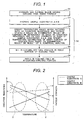
- Fig. 1 is a flowchart showing the method for manufacturing a gas turbine blade of the present invention.
- a gas turbine blade of the invention includes following steps:
- the above coating step (S2) includes following steps:
- the first step involves the attainment of the two specifications, one of which is to specify the temperature range which satisfies both of oxidation resistance and fatigue strength based on an examination result of a temperature dependency of each of the oxidation resistance and fatigue strength of each of the sample substrates A and B, and the other of which is to specify the temperature distribution of the inner surface of the cooling pass.
- the order of these specifications is not particularly limited. These may be simultaneously performed.
- the temperature environment of any gas turbine blade is varied in accordance with each of its portions, such as its portion which combustion gas collides directly with, so that the portion easily turns into a relatively high temperature, and its portion which does not directly contact with the combustion gas not to be easily raised in temperature.
- the environment temperature of the inner surface of a cooling pass located inside the gas turbine blade is also varied on the basis of a temperature environment variation in the outer surface of the gas turbine blade.
- the first step includes the specification of a temperature range in which both the improvement in the oxidation and a restraint of a decline in the fatigue strength can be satisfied.
- the temperature distribution is specified to match this temperature distribution with the temperature range in which both the improvement in the oxidation resistance and the restraint of the fatigue strength decline can be satisfied, thereby preparing the setting of an optimal Al-coating-applying region.
- This step is the first step (S4).
- the Al-coating-applying portion, in the inner surface of the cooling pass is set as the temperature range on the basis of the respective temperature dependencies of the oxidation resistance and the fatigue strength of each of the sample substrates A and B.
- Al coating is next applied only into the set Al-coating-applying portion in a third step (S6).
- the method for manufacturing a gas turbine blade of the present invention Al coating is applied only into desired portions of the inner surface of the cooling pass of the gas turbine blade.
- the method can cause the gas turbine blade to satisfy both of an improvement in endurance (improvement in oxidation resistance) and a sure gain of strength reliability (restraint of a decline in fatigue strength).
- Ni-based alloy suitable for the gas turbine blade is prepared and precisely casted and then the resultant is subjected to machine work to yield a gas turbine blade having at the inside thereof a cooling pass.
- a preferable composition of Ni-based alloy for example, is Ni-13.8Cr-6.8Co-1.8Mo-4.0W-4.0Al-2.8Ta-1.2Nb-3.4Ti-0.015B-0.14C (mass %).
- sample substrate A a substrate which comprises same composition of an actual machine of the gas turbine blade is prepared (sample substrate A), and a substrate which is applied an Al coating to the sample substrate A is prepared (sample substrate B).
- the temperature distribution of the inner surface of the cooling pass is beforehand specified.
- the manner for specifying the temperature distribution may be various, and examples thereof include a specifying manner using a numerical analysis (simulation) or any other analyzing process, a specifying manner using a presumption from a damage of the inner surface of the cooling pass of an actually used gas turbine blade, and a specifying manner using a presumption from a change in an alloy microstructure used as a substrate of the gas turbine blade.
- an appropriate manner is selected from, for example, above-mentioned specifying manners, or two or more selected therefrom are combined with each other. The selected manner or the combination is used to specify the temperature distribution in the inner surface of the cooling pass of the gas turbine blade.
- the fatigue strength of each of the substrates A and B is measured. While the respective fatigue strengths of the substrate A and B are compared with each other, the temperature dependencies of the fatigue strengths of these substrates are evaluated.
- Fig. 2 is a schematic graph demonstrating the temperature dependency of each of the oxidation resistance and fatigue strength of each of the substrates A and B.
- the temperature dependency of the oxidation resistance in the range of relatively low temperatures (for example, the range of about 500 to 600°C, or temperatures lower than the range), a large difference is not generated in oxidation resistance performance between the substrates A and B. However, with a rise in the temperature, the difference between the two increases. In the range of relatively high temperatures (for example, the range of about 800 to 1000°C, which corresponds to a region Y in Fig. 2 ), the difference between the two is remarkably large.
- the region Y in Fig. 2 is a temperature range in which Al coating is to be applied.
- the region X in Fig. 2 is a temperature range in which Al coating is not to be applied.
- the inventors have made experiments for inspecting the temperature dependency of each of the oxidation resistances and fatigue strengths shown in Fig. 2 .
- Figs. 3 and 4 are, respectively, a graph showing inspecting-experiment-results of the oxidation resistances of the substrates A and B; and a graph showing ones of the fatigue strengths of the same.
- any minus value represents the peeling quantity when the produced scale has peeled.
- the substrates A and B are equivalent to each other in mass change to be equivalent to each other in oxidation resistance.
- the substrate B is about 30% lower than the substrate A in mass change to be largely improved in oxidation resistance.
- the temperature range for Al coating is preferably a temperature range higher than 800°C, more preferably, a temperature range of about 900°C or higher, and corresponds to the region Y in Fig. 2 .
- Fig. 4 is concerned with the number of cycles to failure of each of two species of each of the substrates A and B, these substrates A and B being caused to correspond to each other about each of these species.
- the number of cycles to failure of the substrate A is 4 times that of the substrate B.
- the former is 6 times the latter.
- the regions X and Y (temperature range) shown in Fig. 2 are specified, and then a portion corresponding to the region Y is specified for the temperature distribution specified according to the item "Manner for Specifying Temperature Distribution” in the first step. In this way, an Al-coating-applying portion of the gas turbine blade is set.
- a portion F (corresponding to the temperature range Y in Fig. 2 ) is specified as the Al-coating-applying portion.
- the portion F is a portion which can turn into a relatively high temperature and which is a portion of an inner surface S of a cooling pass P of the gas turbine blade W.
- Al coating is applied on the basis of the Al-coating-applying portion set in the second step.
- Al pack method For applying the Al coating the so-called Al pack method is used, which makes use of Al pack powder composed of Al powder or Al alloy powder, as an Al supply source, and powder of a halide such as ammonium chloride or sodium chloride, as an activator for producing a gaseous halogen compound containing Al.
- a halide such as ammonium chloride or sodium chloride
- hydrogen chloride gas (HCl) generated by sublimating ammonium chloride (NH 4 Cl) by heat treatment reacts with Al of the Al pack powder, and AlCl or AlCl 3 gas is generated and transports Al of the Al pack powder in the inner surface of the cooling pass.
- the Al pack powder can be prepared by mixing commercial powder of Al or Al alloy powder and powder of a halide.
- Preferable conditions of the above heat treatment is at 700 to 1000°C for 3-24 hours in an inert atmosphere or in a vaccum.
- the preferable range of a thickness of the Al coating is 50-150 ⁇ m. If the thickness is less than 50 ⁇ m, the coating of the inner surface of the cooling pass is not enough. In view of a process cost, it is preferable that the thickness of the Al coating is 150 ⁇ m or less.
- the heat treatment time range is determined by desired thickness of the Al coating. The heat treatment is carried out in an inert atmosphere or in a vacuum so as to prevent a oxidation of Al of the Al pack powder.
- a structure of the Al coating produced by the Al pack method described above differs from a structure of a coating obtained by a thermal spraying, EB-PVD or CVD.
- the surface of the Al coating of the present invention has an asperity structure, and the powder of Al pack slightly remains. There is a possibility that these characters can be observed by a cross-sectional observation of electron microscope. This is a coating feature obtained by the Al pack method which is not observed of the coating obtained by other methods.
- Al pack powder is filled into the Al-coating-applying portion while inactive and adsorbable powder made of, for example, Al 2 O 3 , MgO or CaO is filled into the Al-coating-unapplying portion.
- the inactive and adsorbable powder Since the inactive and adsorbable powder has, in the surface thereof, many pores to be excellent in gas absorptivity, the powder produces an advantageous effect of adsorbing Al-containing gas generated from the Al pack powder filled into the Al-coating-applying portion, so as to prevent the precipitation of Al or the formation of an Al coat layer in the Al-coating-unapplying portion of the inner surface of the cooling pass.
- MgO and CaO are basic oxides to be especially good in adsorptivity of an acidic gas generated from the Al pack powder, such as HCl.
- the oxides are particularly preferred as the powder to be filled into the Al-coating-unapplying portion.
- the heating temperature in the Al pack method is at highest about 1000°C.
- Al 2 O 3 , MgO and CaO are not sintered at such a temperature.
- the oxides are easily removed from the cooling path after the Al pack method, not to cause a problem caused by other masking methods, i.e., a problem that the cooling pass is blocked caused by a matter that the masking component remains inside the cooling pass.
- the Al-coating-applying portion can be selected with a good precision. Moreover, basically, the filling of the powder can be performed in the same way as used for that of the Al pack powder. Thus, a step peculiar to the filling of the powder is unnecessary. Furthermore, at the time of the powder filling, no especial apparatus or tool is necessary so that the powder filling into the cooling pass can easily be attained.
- a coat C based on the Al coating has been applied only into desired portions of the inner surface S of the cooling pass P.
- Ni-based alloy Ni-13.8Cr-6.8Co-1.8Mo-4.0W-4.0Al-2.8Ta-1.2Nb-3.4Ti-0.015B -0.14C (mass %)
- the oxidation resistances of the substrates were each evaluated, according to the exposure test in the atmosphere, through a weight change following oxidation.
- the test temperature was varied in the range of temperatures of the cooling pass inner surface.
- Some samples of the substrates were subjected to the test at longest over 4000 hours.
- the weight change based on oxidation was smaller by the Al coating than about the untreated substrate.
- the advantageous effect of improving the oxidation resistance by the Al coating was obtained.
- the fatigue test was made in a temperature range equivalent to that in the oxidation resistance test.
- the Al coating made the fatigue strength low; however, the number of cycles to failure of the Al coated substrate was about 75% of that of the untreated substrate. However, at temperatures lower than 800°C, the Al coated substrate was abruptly lowered in fatigue strength. At 600°C, the fatigue strength was lowered to 25% of that of the untreated substrate.
- the temperature range for Al coating application was set into the range of about 800 to 900°C, or to a higher temperature.
- this range was compared with the previously gained temperature distribution, an Al-coating-applying portion was decided.
- Al pack powder was filled into the Al-coating-applying portion while Al 2 O 3 powder into the Al-coating-unapplying portion.
- the operations were controlled through the respective weights of the powders.
- the respective bulk densities of the Al pack powder and the Al 2 O 3 were measured.
- the density of the Al pack powder was about 1.45 g/cm 3
- that of the Al 2 O 3 was 1.15 g/cm 3 .
- the volume of the cooling pass in the Al-coating-applying port ion, and that in the Al-coating-unapplying portion were gained. From the volumes and the powder densities, the respective weights of the Al pack powder and the Al 2 O 3 powder were calculated out.
- the Al pack powder was filled into sites at the leading edge side and the trailing edge side of the tip of the blade.
- the temporarily sealing tapes were taken away, and the gas turbine blade was set in a heating furnace to be heated in argon gas at 750°C for 3 hours.
- the blade was cooled, and then the Al powder and the Al 2 O 3 powder were removed by causing compressed air to flow into the cooling pass.
- the Al 2 O 3 powder was easily removed without being sintered.
- the Al powder and the Al 2 O 3 powder can also be removed by flowing water.
- the blade was cut and examined to check the positional precision of the Al-coating-applying portion and the Al-coating-unapplying portion, and the microstructure of a boundary between the portions.
- the error between the beforehand-set Al-coating-applying portion and an actual Al-coating-applying portion was 10 mm or less on average.
- the selection of the Al-coating-applying portion was attainable with a high precision.
- Fig. 7 is a sectional SEMphotograph of the boundary between the Al-coating-applying portion and the Al-coating-unapplying portion. From Fig. 7 , it is understood that no Al coat layer was formed in the Al-coating-unapplying portion and Al-containing gas was adsorbed onto the Al 2 O 3 powder to succeed in the prevention of Al precipitation and the formation of any Al coat layer onto the inner surface of the cooling pass.
- the boundary is present to have an acute angle, there is a risk that the angular corner functions as a point at which a fatigue crack is generated.
- the shape of the boundary in the present example is preferred for the fatigue strength of the blade.
- the method for manufacturing a turbine blade of the present invention makes it possible to improve the oxidation resistance of the inner surface of the cooling pass of a gas turbine blade; set, with a high precision, an Al-coating-applying portion producing no bad effect on the fatigue strength of the blade; and apply an Al coat layer selectively to ensure the endurance and the strength reliability of the gas turbine blade.
Landscapes
- Engineering & Computer Science (AREA)
- Chemical & Material Sciences (AREA)
- Mechanical Engineering (AREA)
- Materials Engineering (AREA)
- Chemical Kinetics & Catalysis (AREA)
- Metallurgy (AREA)
- Organic Chemistry (AREA)
- General Engineering & Computer Science (AREA)
- Turbine Rotor Nozzle Sealing (AREA)
- Other Surface Treatments For Metallic Materials (AREA)
Claims (1)
- Verfahren zum Herstellen eines Gasturbinenrotorblatts, das die folgenden Schritte umfasst:Herstellen eines Gasturbinenrotorblatts (W), das einen innenliegenden Kühldurchgang (P) besitzt; undteilweises Beschichten einer Innenfläche (S) des Kühldurchgangs (P) mit Al, dadurch gekennzeichnet, dassder Schritt des teilweisen Beschichtens einer Innenfläche (S) des Kühldurchgangs (P) mit Al Folgendes umfasst:einen Mustersubstratvorbereitungsschritt zum Vorbereiten eines Mustersubstrats A, das dieselbe Zusammensetzung wie eine tatsächliche Maschine des Gasturbinenrotorblatts (W) umfasst, und zum Vorbereiten eines Mustersubstrats B, das das Mustersubstrat A ist, auf das eine Al-Beschichtung aufgebracht ist;einen ersten Schritt des Spezifizierens der Temperaturverteilung der Innenfläche des Kühldurchgangs auf der Grundlage eines Untersuchungsergebnisses oder eines Ergebnisses einer numerischen Analyse, der durch den Schritt des Spezifizierens eines Temperaturbereichs von 800 °C bis 1000 °C gefolgt wird, was sowohl die Oxidationsbeständigkeit als auch die Dauerfestigkeit auf der Grundlage eines Untersuchungsergebnisses einer Temperaturabhängigkeit sowohl der Oxidationsbeständigkeit als auch der Dauerfestigkeit jedes der Mustersubstrate A und B erfüllt;einen zweiten Schritt des Festlegens eines Al-Beschichtungsaufbringungsabschnitts der Innenfläche (S) des Kühldurchgangs (P) auf der Grundlage des Temperaturbereichs, der sowohl die Oxidationsbeständigkeit als auch die Dauerfestigkeit erfüllt, und auf der Grundlage der Temperaturverteilung der Innenfläche des Kühldurchgangs, die im ersten Schritt spezifiziert wurde; undeinen dritten Schritt des Aufbringens einer Al-Beschichtung lediglich im festgelegten Al-Beschichtungsaufbringungsabschnitt; wobeider dritte Schritt ferner die folgenden Schritte umfasst:Füllen des Kühldurchgangs (P) mit Al-Packungspulver, das Al-Pulver oder Al-Legierungspulver oder nicht aktives und adsorbierbares Pulver aus einem adsorbierbaren Metalloxid, das aus Al2O3, MgO oder CaO hergestellt ist, umfasst, wobei das adsorbierbare Metalloxid in einen Al-Beschichtungsentfernungsabschnitt der Innenfläche (S) des Kühldurchgangs (P) gefüllt ist, der nicht der Al-Beschichtungsaufbringungsabschnitt ist und der nicht mit Al-Packungspulver gefüllt ist;Erhitzen des Turbinenrotorblattes (W) in Argon-Gas auf im Bereich von 700 bis 1000 °C; undKühlen des Turbinenrotorblattes (W) und Entfernen des adsorbierbaren Metalloxids im Kühldurchgang (P).
Applications Claiming Priority (1)
| Application Number | Priority Date | Filing Date | Title |
|---|---|---|---|
| JP2013112755A JP6184172B2 (ja) | 2013-05-29 | 2013-05-29 | Alコーティング方法とガスタービン翼の製造方法 |
Publications (3)
| Publication Number | Publication Date |
|---|---|
| EP2808418A2 EP2808418A2 (de) | 2014-12-03 |
| EP2808418A3 EP2808418A3 (de) | 2015-03-11 |
| EP2808418B1 true EP2808418B1 (de) | 2019-07-10 |
Family
ID=50897374
Family Applications (1)
| Application Number | Title | Priority Date | Filing Date |
|---|---|---|---|
| EP14170194.6A Active EP2808418B1 (de) | 2013-05-29 | 2014-05-28 | Verfahren zur Herstellung einer Turbinenschaufel |
Country Status (3)
| Country | Link |
|---|---|
| US (1) | US9732411B2 (de) |
| EP (1) | EP2808418B1 (de) |
| JP (1) | JP6184172B2 (de) |
Families Citing this family (3)
| Publication number | Priority date | Publication date | Assignee | Title |
|---|---|---|---|---|
| US10472972B2 (en) * | 2015-12-01 | 2019-11-12 | General Electric Company | Thermal management of CMC articles having film holes |
| CN111168327B (zh) * | 2019-12-30 | 2021-10-26 | 哈尔滨汽轮机厂有限责任公司 | 一种强力磨床加工叶片装配内背弧方法 |
| CN120060767B (zh) * | 2025-04-27 | 2025-07-22 | 西安交通大学 | 燃气轮机叶片激光预热制备表面带有纵向裂纹涂层的方法 |
Family Cites Families (16)
| Publication number | Priority date | Publication date | Assignee | Title |
|---|---|---|---|---|
| JP3315246B2 (ja) | 1994-05-23 | 2002-08-19 | 株式会社東芝 | 金属コーティング材料 |
| JP3651710B2 (ja) * | 1996-01-11 | 2005-05-25 | 株式会社東芝 | ガスタービン翼の化学蒸着アルミナイズド被膜形成方法 |
| US6146696A (en) | 1999-05-26 | 2000-11-14 | General Electric Company | Process for simultaneously aluminizing nickel-base and cobalt-base superalloys |
| JP2001166819A (ja) * | 1999-12-13 | 2001-06-22 | Toshiba Corp | 原動機の異常診断・寿命診断システム |
| JP2001330542A (ja) * | 2000-05-22 | 2001-11-30 | Toshiba Corp | ガスタービンコーティング部品の疲労寿命評価方法および疲労寿命評価装置 |
| US6485262B1 (en) * | 2001-07-06 | 2002-11-26 | General Electric Company | Methods and apparatus for extending gas turbine engine airfoils useful life |
| JP4460806B2 (ja) * | 2001-09-28 | 2010-05-12 | 株式会社東芝 | ガスタービン高温部品の寿命管理方法 |
| US7976940B2 (en) * | 2002-04-10 | 2011-07-12 | Siemens Aktiengesellschaft | Component, method for coating a component, and powder |
| US6932570B2 (en) * | 2002-05-23 | 2005-08-23 | General Electric Company | Methods and apparatus for extending gas turbine engine airfoils useful life |
| US7008553B2 (en) | 2003-01-09 | 2006-03-07 | General Electric Company | Method for removing aluminide coating from metal substrate and turbine engine part so treated |
| US6896488B2 (en) * | 2003-06-05 | 2005-05-24 | General Electric Company | Bond coat process for thermal barrier coating |
| US7252480B2 (en) | 2004-12-17 | 2007-08-07 | General Electric Company | Methods for generation of dual thickness internal pack coatings and objects produced thereby |
| US20060193981A1 (en) * | 2005-02-25 | 2006-08-31 | General Electric Company | Apparatus and method for masking vapor phase aluminide coating to achieve internal coating of cooling passages |
| US7371428B2 (en) * | 2005-11-28 | 2008-05-13 | Howmet Corporation | Duplex gas phase coating |
| US20070141385A1 (en) * | 2005-12-21 | 2007-06-21 | General Electric Company | Method of coating gas turbine components |
| US8545185B2 (en) | 2007-12-19 | 2013-10-01 | General Electric Company | Turbine engine components with environmental protection for interior passages |
-
2013
- 2013-05-29 JP JP2013112755A patent/JP6184172B2/ja not_active Expired - Fee Related
-
2014
- 2014-05-28 US US14/289,432 patent/US9732411B2/en not_active Expired - Fee Related
- 2014-05-28 EP EP14170194.6A patent/EP2808418B1/de active Active
Non-Patent Citations (1)
| Title |
|---|
| None * |
Also Published As
| Publication number | Publication date |
|---|---|
| JP6184172B2 (ja) | 2017-08-23 |
| EP2808418A2 (de) | 2014-12-03 |
| US20140356186A1 (en) | 2014-12-04 |
| US9732411B2 (en) | 2017-08-15 |
| EP2808418A3 (de) | 2015-03-11 |
| JP2014231780A (ja) | 2014-12-11 |
Similar Documents
| Publication | Publication Date | Title |
|---|---|---|
| JP6126852B2 (ja) | ガスタービン部品のコーティング及びコーティング方法 | |
| EP2060653B1 (de) | Schlickerzusammensetzungen für Aluminiddiffusionsbeschichtungen | |
| JP4053477B2 (ja) | オーバーレイコーティングの堆積方法 | |
| US6413582B1 (en) | Method for forming metallic-based coating | |
| EP1811061A2 (de) | Beschichtung aus mit Yttriumoxid stabilisiertem Zirkonoxid mit gegen geschmolzenes Silicat resistenter Außenschicht | |
| Genova et al. | Diffusion aluminide coating modified via electroless nickel plating for Ni-based superalloy protection | |
| EP1956116A1 (de) | Entfernung von Wärmesperrenbeschichtungen | |
| US20100330295A1 (en) | Method for providing ductile environmental coating having fatigue and corrosion resistance | |
| US20060141283A1 (en) | Low cost inovative diffused MCrAIY coatings | |
| JP2000199401A (ja) | タ―ビン翼形部の補修方法 | |
| US7026011B2 (en) | Aluminide coating of gas turbine engine blade | |
| EP2808418B1 (de) | Verfahren zur Herstellung einer Turbinenschaufel | |
| JP4579383B2 (ja) | 緻密セラミック遮熱皮膜を表面から除去する方法 | |
| EP1123987A1 (de) | Reparierbare Diffusionsaluminidbeschichtungen | |
| US6482470B1 (en) | Diffusion aluminide coated metallic substrate including a thin diffusion portion of controlled thickness | |
| EP1788109A1 (de) | Verfahren zum selektiven Aluminid-Beschichten | |
| JP2003201803A (ja) | ハフニアを備える安定化ジルコニアの遮熱コーティング | |
| WO2005038074A1 (en) | Method of applying a thermal barrier coating system to a superalloy substrate | |
| EP3048183B1 (de) | Applikationsverfahren für korrosionsbeständige beschichtung | |
| US8808803B2 (en) | Coating method for reactive metal | |
| CN101365815A (zh) | 用于制备保护涂层的合金组合物及其用途及应用方法以及涂覆有该组合物的高温合金制品 | |
| CN114585769A (zh) | 由包含铼和/或钌的高温合金制成的飞行器部件及其制造方法 | |
| EP3492623B1 (de) | Verfahren zur reduzierung der oberflächenrauheit |
Legal Events
| Date | Code | Title | Description |
|---|---|---|---|
| PUAI | Public reference made under article 153(3) epc to a published international application that has entered the european phase |
Free format text: ORIGINAL CODE: 0009012 |
|
| 17P | Request for examination filed |
Effective date: 20140704 |
|
| AK | Designated contracting states |
Kind code of ref document: A2 Designated state(s): AL AT BE BG CH CY CZ DE DK EE ES FI FR GB GR HR HU IE IS IT LI LT LU LV MC MK MT NL NO PL PT RO RS SE SI SK SM TR |
|
| AX | Request for extension of the european patent |
Extension state: BA ME |
|
| PUAL | Search report despatched |
Free format text: ORIGINAL CODE: 0009013 |
|
| AK | Designated contracting states |
Kind code of ref document: A3 Designated state(s): AL AT BE BG CH CY CZ DE DK EE ES FI FR GB GR HR HU IE IS IT LI LT LU LV MC MK MT NL NO PL PT RO RS SE SI SK SM TR |
|
| AX | Request for extension of the european patent |
Extension state: BA ME |
|
| RIC1 | Information provided on ipc code assigned before grant |
Ipc: C23C 10/36 20060101ALI20150203BHEP Ipc: C23C 10/60 20060101ALI20150203BHEP Ipc: F01D 5/28 20060101ALI20150203BHEP Ipc: F01D 5/18 20060101ALI20150203BHEP Ipc: C23C 10/48 20060101AFI20150203BHEP Ipc: C23C 10/04 20060101ALI20150203BHEP |
|
| RAP1 | Party data changed (applicant data changed or rights of an application transferred) |
Owner name: MITSUBISHI HITACHI POWER SYSTEMS, LTD. |
|
| 17Q | First examination report despatched |
Effective date: 20160212 |
|
| STAA | Information on the status of an ep patent application or granted ep patent |
Free format text: STATUS: EXAMINATION IS IN PROGRESS |
|
| GRAP | Despatch of communication of intention to grant a patent |
Free format text: ORIGINAL CODE: EPIDOSNIGR1 |
|
| STAA | Information on the status of an ep patent application or granted ep patent |
Free format text: STATUS: GRANT OF PATENT IS INTENDED |
|
| INTG | Intention to grant announced |
Effective date: 20190130 |
|
| GRAS | Grant fee paid |
Free format text: ORIGINAL CODE: EPIDOSNIGR3 |
|
| GRAA | (expected) grant |
Free format text: ORIGINAL CODE: 0009210 |
|
| STAA | Information on the status of an ep patent application or granted ep patent |
Free format text: STATUS: THE PATENT HAS BEEN GRANTED |
|
| AK | Designated contracting states |
Kind code of ref document: B1 Designated state(s): AL AT BE BG CH CY CZ DE DK EE ES FI FR GB GR HR HU IE IS IT LI LT LU LV MC MK MT NL NO PL PT RO RS SE SI SK SM TR |
|
| REG | Reference to a national code |
Ref country code: GB Ref legal event code: FG4D |
|
| REG | Reference to a national code |
Ref country code: CH Ref legal event code: EP Ref country code: AT Ref legal event code: REF Ref document number: 1153654 Country of ref document: AT Kind code of ref document: T Effective date: 20190715 |
|
| REG | Reference to a national code |
Ref country code: IE Ref legal event code: FG4D |
|
| REG | Reference to a national code |
Ref country code: DE Ref legal event code: R096 Ref document number: 602014049749 Country of ref document: DE |
|
| REG | Reference to a national code |
Ref country code: NL Ref legal event code: MP Effective date: 20190710 |
|
| REG | Reference to a national code |
Ref country code: LT Ref legal event code: MG4D |
|
| REG | Reference to a national code |
Ref country code: AT Ref legal event code: MK05 Ref document number: 1153654 Country of ref document: AT Kind code of ref document: T Effective date: 20190710 |
|
| PG25 | Lapsed in a contracting state [announced via postgrant information from national office to epo] |
Ref country code: BG Free format text: LAPSE BECAUSE OF FAILURE TO SUBMIT A TRANSLATION OF THE DESCRIPTION OR TO PAY THE FEE WITHIN THE PRESCRIBED TIME-LIMIT Effective date: 20191010 Ref country code: PT Free format text: LAPSE BECAUSE OF FAILURE TO SUBMIT A TRANSLATION OF THE DESCRIPTION OR TO PAY THE FEE WITHIN THE PRESCRIBED TIME-LIMIT Effective date: 20191111 Ref country code: NL Free format text: LAPSE BECAUSE OF FAILURE TO SUBMIT A TRANSLATION OF THE DESCRIPTION OR TO PAY THE FEE WITHIN THE PRESCRIBED TIME-LIMIT Effective date: 20190710 Ref country code: LT Free format text: LAPSE BECAUSE OF FAILURE TO SUBMIT A TRANSLATION OF THE DESCRIPTION OR TO PAY THE FEE WITHIN THE PRESCRIBED TIME-LIMIT Effective date: 20190710 Ref country code: HR Free format text: LAPSE BECAUSE OF FAILURE TO SUBMIT A TRANSLATION OF THE DESCRIPTION OR TO PAY THE FEE WITHIN THE PRESCRIBED TIME-LIMIT Effective date: 20190710 Ref country code: SE Free format text: LAPSE BECAUSE OF FAILURE TO SUBMIT A TRANSLATION OF THE DESCRIPTION OR TO PAY THE FEE WITHIN THE PRESCRIBED TIME-LIMIT Effective date: 20190710 Ref country code: AT Free format text: LAPSE BECAUSE OF FAILURE TO SUBMIT A TRANSLATION OF THE DESCRIPTION OR TO PAY THE FEE WITHIN THE PRESCRIBED TIME-LIMIT Effective date: 20190710 Ref country code: FI Free format text: LAPSE BECAUSE OF FAILURE TO SUBMIT A TRANSLATION OF THE DESCRIPTION OR TO PAY THE FEE WITHIN THE PRESCRIBED TIME-LIMIT Effective date: 20190710 Ref country code: NO Free format text: LAPSE BECAUSE OF FAILURE TO SUBMIT A TRANSLATION OF THE DESCRIPTION OR TO PAY THE FEE WITHIN THE PRESCRIBED TIME-LIMIT Effective date: 20191010 |
|
| PG25 | Lapsed in a contracting state [announced via postgrant information from national office to epo] |
Ref country code: ES Free format text: LAPSE BECAUSE OF FAILURE TO SUBMIT A TRANSLATION OF THE DESCRIPTION OR TO PAY THE FEE WITHIN THE PRESCRIBED TIME-LIMIT Effective date: 20190710 Ref country code: IS Free format text: LAPSE BECAUSE OF FAILURE TO SUBMIT A TRANSLATION OF THE DESCRIPTION OR TO PAY THE FEE WITHIN THE PRESCRIBED TIME-LIMIT Effective date: 20191110 Ref country code: RS Free format text: LAPSE BECAUSE OF FAILURE TO SUBMIT A TRANSLATION OF THE DESCRIPTION OR TO PAY THE FEE WITHIN THE PRESCRIBED TIME-LIMIT Effective date: 20190710 Ref country code: LV Free format text: LAPSE BECAUSE OF FAILURE TO SUBMIT A TRANSLATION OF THE DESCRIPTION OR TO PAY THE FEE WITHIN THE PRESCRIBED TIME-LIMIT Effective date: 20190710 Ref country code: GR Free format text: LAPSE BECAUSE OF FAILURE TO SUBMIT A TRANSLATION OF THE DESCRIPTION OR TO PAY THE FEE WITHIN THE PRESCRIBED TIME-LIMIT Effective date: 20191011 Ref country code: AL Free format text: LAPSE BECAUSE OF FAILURE TO SUBMIT A TRANSLATION OF THE DESCRIPTION OR TO PAY THE FEE WITHIN THE PRESCRIBED TIME-LIMIT Effective date: 20190710 |
|
| PG25 | Lapsed in a contracting state [announced via postgrant information from national office to epo] |
Ref country code: TR Free format text: LAPSE BECAUSE OF FAILURE TO SUBMIT A TRANSLATION OF THE DESCRIPTION OR TO PAY THE FEE WITHIN THE PRESCRIBED TIME-LIMIT Effective date: 20190710 |
|
| PG25 | Lapsed in a contracting state [announced via postgrant information from national office to epo] |
Ref country code: RO Free format text: LAPSE BECAUSE OF FAILURE TO SUBMIT A TRANSLATION OF THE DESCRIPTION OR TO PAY THE FEE WITHIN THE PRESCRIBED TIME-LIMIT Effective date: 20190710 Ref country code: IT Free format text: LAPSE BECAUSE OF FAILURE TO SUBMIT A TRANSLATION OF THE DESCRIPTION OR TO PAY THE FEE WITHIN THE PRESCRIBED TIME-LIMIT Effective date: 20190710 Ref country code: EE Free format text: LAPSE BECAUSE OF FAILURE TO SUBMIT A TRANSLATION OF THE DESCRIPTION OR TO PAY THE FEE WITHIN THE PRESCRIBED TIME-LIMIT Effective date: 20190710 Ref country code: DK Free format text: LAPSE BECAUSE OF FAILURE TO SUBMIT A TRANSLATION OF THE DESCRIPTION OR TO PAY THE FEE WITHIN THE PRESCRIBED TIME-LIMIT Effective date: 20190710 Ref country code: PL Free format text: LAPSE BECAUSE OF FAILURE TO SUBMIT A TRANSLATION OF THE DESCRIPTION OR TO PAY THE FEE WITHIN THE PRESCRIBED TIME-LIMIT Effective date: 20190710 |
|
| PG25 | Lapsed in a contracting state [announced via postgrant information from national office to epo] |
Ref country code: SK Free format text: LAPSE BECAUSE OF FAILURE TO SUBMIT A TRANSLATION OF THE DESCRIPTION OR TO PAY THE FEE WITHIN THE PRESCRIBED TIME-LIMIT Effective date: 20190710 Ref country code: SM Free format text: LAPSE BECAUSE OF FAILURE TO SUBMIT A TRANSLATION OF THE DESCRIPTION OR TO PAY THE FEE WITHIN THE PRESCRIBED TIME-LIMIT Effective date: 20190710 Ref country code: IS Free format text: LAPSE BECAUSE OF FAILURE TO SUBMIT A TRANSLATION OF THE DESCRIPTION OR TO PAY THE FEE WITHIN THE PRESCRIBED TIME-LIMIT Effective date: 20200224 Ref country code: CZ Free format text: LAPSE BECAUSE OF FAILURE TO SUBMIT A TRANSLATION OF THE DESCRIPTION OR TO PAY THE FEE WITHIN THE PRESCRIBED TIME-LIMIT Effective date: 20190710 |
|
| REG | Reference to a national code |
Ref country code: DE Ref legal event code: R097 Ref document number: 602014049749 Country of ref document: DE |
|
| PLBE | No opposition filed within time limit |
Free format text: ORIGINAL CODE: 0009261 |
|
| STAA | Information on the status of an ep patent application or granted ep patent |
Free format text: STATUS: NO OPPOSITION FILED WITHIN TIME LIMIT |
|
| PG2D | Information on lapse in contracting state deleted |
Ref country code: IS |
|
| 26N | No opposition filed |
Effective date: 20200603 |
|
| PG25 | Lapsed in a contracting state [announced via postgrant information from national office to epo] |
Ref country code: SI Free format text: LAPSE BECAUSE OF FAILURE TO SUBMIT A TRANSLATION OF THE DESCRIPTION OR TO PAY THE FEE WITHIN THE PRESCRIBED TIME-LIMIT Effective date: 20190710 |
|
| REG | Reference to a national code |
Ref country code: DE Ref legal event code: R082 Ref document number: 602014049749 Country of ref document: DE Representative=s name: MERH-IP MATIAS ERNY REICHL HOFFMANN PATENTANWA, DE Ref country code: DE Ref legal event code: R081 Ref document number: 602014049749 Country of ref document: DE Owner name: MITSUBISHI POWER, LTD., JP Free format text: FORMER OWNER: MITSUBISHI HITACHI POWER SYSTEMS, LTD., YOKOHAMA, JP |
|
| PG25 | Lapsed in a contracting state [announced via postgrant information from national office to epo] |
Ref country code: CH Free format text: LAPSE BECAUSE OF NON-PAYMENT OF DUE FEES Effective date: 20200531 Ref country code: MC Free format text: LAPSE BECAUSE OF FAILURE TO SUBMIT A TRANSLATION OF THE DESCRIPTION OR TO PAY THE FEE WITHIN THE PRESCRIBED TIME-LIMIT Effective date: 20190710 Ref country code: LI Free format text: LAPSE BECAUSE OF NON-PAYMENT OF DUE FEES Effective date: 20200531 |
|
| REG | Reference to a national code |
Ref country code: BE Ref legal event code: MM Effective date: 20200531 |
|
| PG25 | Lapsed in a contracting state [announced via postgrant information from national office to epo] |
Ref country code: LU Free format text: LAPSE BECAUSE OF NON-PAYMENT OF DUE FEES Effective date: 20200528 |
|
| PG25 | Lapsed in a contracting state [announced via postgrant information from national office to epo] |
Ref country code: IE Free format text: LAPSE BECAUSE OF NON-PAYMENT OF DUE FEES Effective date: 20200528 |
|
| PG25 | Lapsed in a contracting state [announced via postgrant information from national office to epo] |
Ref country code: BE Free format text: LAPSE BECAUSE OF NON-PAYMENT OF DUE FEES Effective date: 20200531 |
|
| PG25 | Lapsed in a contracting state [announced via postgrant information from national office to epo] |
Ref country code: MT Free format text: LAPSE BECAUSE OF FAILURE TO SUBMIT A TRANSLATION OF THE DESCRIPTION OR TO PAY THE FEE WITHIN THE PRESCRIBED TIME-LIMIT Effective date: 20190710 Ref country code: CY Free format text: LAPSE BECAUSE OF FAILURE TO SUBMIT A TRANSLATION OF THE DESCRIPTION OR TO PAY THE FEE WITHIN THE PRESCRIBED TIME-LIMIT Effective date: 20190710 |
|
| PG25 | Lapsed in a contracting state [announced via postgrant information from national office to epo] |
Ref country code: MK Free format text: LAPSE BECAUSE OF FAILURE TO SUBMIT A TRANSLATION OF THE DESCRIPTION OR TO PAY THE FEE WITHIN THE PRESCRIBED TIME-LIMIT Effective date: 20190710 |
|
| REG | Reference to a national code |
Ref country code: FR Ref legal event code: PLFP Year of fee payment: 10 |
|
| PGFP | Annual fee paid to national office [announced via postgrant information from national office to epo] |
Ref country code: FR Payment date: 20230411 Year of fee payment: 10 Ref country code: DE Payment date: 20230404 Year of fee payment: 10 |
|
| PGFP | Annual fee paid to national office [announced via postgrant information from national office to epo] |
Ref country code: GB Payment date: 20230406 Year of fee payment: 10 |
|
| REG | Reference to a national code |
Ref country code: DE Ref legal event code: R119 Ref document number: 602014049749 Country of ref document: DE |
|
| GBPC | Gb: european patent ceased through non-payment of renewal fee |
Effective date: 20240528 |
|
| PG25 | Lapsed in a contracting state [announced via postgrant information from national office to epo] |
Ref country code: DE Free format text: LAPSE BECAUSE OF NON-PAYMENT OF DUE FEES Effective date: 20241203 |
|
| PG25 | Lapsed in a contracting state [announced via postgrant information from national office to epo] |
Ref country code: FR Free format text: LAPSE BECAUSE OF NON-PAYMENT OF DUE FEES Effective date: 20240531 |
|
| PG25 | Lapsed in a contracting state [announced via postgrant information from national office to epo] |
Ref country code: GB Free format text: LAPSE BECAUSE OF NON-PAYMENT OF DUE FEES Effective date: 20240528 |